EP0394845A2 - Vorrichtung zur Herstellung von Bauteilen aus laminiertem Bandmaterial - Google Patents
Vorrichtung zur Herstellung von Bauteilen aus laminiertem Bandmaterial Download PDFInfo
- Publication number
- EP0394845A2 EP0394845A2 EP90107441A EP90107441A EP0394845A2 EP 0394845 A2 EP0394845 A2 EP 0394845A2 EP 90107441 A EP90107441 A EP 90107441A EP 90107441 A EP90107441 A EP 90107441A EP 0394845 A2 EP0394845 A2 EP 0394845A2
- Authority
- EP
- European Patent Office
- Prior art keywords
- support means
- strip
- storage
- sections
- stacking unit
- Prior art date
- Legal status (The legal status is an assumption and is not a legal conclusion. Google has not performed a legal analysis and makes no representation as to the accuracy of the status listed.)
- Withdrawn
Links
Images

Classifications
-
- B—PERFORMING OPERATIONS; TRANSPORTING
- B29—WORKING OF PLASTICS; WORKING OF SUBSTANCES IN A PLASTIC STATE IN GENERAL
- B29C—SHAPING OR JOINING OF PLASTICS; SHAPING OF MATERIAL IN A PLASTIC STATE, NOT OTHERWISE PROVIDED FOR; AFTER-TREATMENT OF THE SHAPED PRODUCTS, e.g. REPAIRING
- B29C70/00—Shaping composites, i.e. plastics material comprising reinforcements, fillers or preformed parts, e.g. inserts
- B29C70/04—Shaping composites, i.e. plastics material comprising reinforcements, fillers or preformed parts, e.g. inserts comprising reinforcements only, e.g. self-reinforcing plastics
- B29C70/28—Shaping operations therefor
- B29C70/54—Component parts, details or accessories; Auxiliary operations, e.g. feeding or storage of prepregs or SMC after impregnation or during ageing
- B29C70/545—Perforating, cutting or machining during or after moulding
-
- B—PERFORMING OPERATIONS; TRANSPORTING
- B29—WORKING OF PLASTICS; WORKING OF SUBSTANCES IN A PLASTIC STATE IN GENERAL
- B29C—SHAPING OR JOINING OF PLASTICS; SHAPING OF MATERIAL IN A PLASTIC STATE, NOT OTHERWISE PROVIDED FOR; AFTER-TREATMENT OF THE SHAPED PRODUCTS, e.g. REPAIRING
- B29C70/00—Shaping composites, i.e. plastics material comprising reinforcements, fillers or preformed parts, e.g. inserts
- B29C70/04—Shaping composites, i.e. plastics material comprising reinforcements, fillers or preformed parts, e.g. inserts comprising reinforcements only, e.g. self-reinforcing plastics
- B29C70/28—Shaping operations therefor
- B29C70/30—Shaping by lay-up, i.e. applying fibres, tape or broadsheet on a mould, former or core; Shaping by spray-up, i.e. spraying of fibres on a mould, former or core
-
- B—PERFORMING OPERATIONS; TRANSPORTING
- B29—WORKING OF PLASTICS; WORKING OF SUBSTANCES IN A PLASTIC STATE IN GENERAL
- B29C—SHAPING OR JOINING OF PLASTICS; SHAPING OF MATERIAL IN A PLASTIC STATE, NOT OTHERWISE PROVIDED FOR; AFTER-TREATMENT OF THE SHAPED PRODUCTS, e.g. REPAIRING
- B29C70/00—Shaping composites, i.e. plastics material comprising reinforcements, fillers or preformed parts, e.g. inserts
- B29C70/04—Shaping composites, i.e. plastics material comprising reinforcements, fillers or preformed parts, e.g. inserts comprising reinforcements only, e.g. self-reinforcing plastics
- B29C70/28—Shaping operations therefor
- B29C70/30—Shaping by lay-up, i.e. applying fibres, tape or broadsheet on a mould, former or core; Shaping by spray-up, i.e. spraying of fibres on a mould, former or core
- B29C70/38—Automated lay-up, e.g. using robots, laying filaments according to predetermined patterns
- B29C70/386—Automated tape laying [ATL]
-
- Y—GENERAL TAGGING OF NEW TECHNOLOGICAL DEVELOPMENTS; GENERAL TAGGING OF CROSS-SECTIONAL TECHNOLOGIES SPANNING OVER SEVERAL SECTIONS OF THE IPC; TECHNICAL SUBJECTS COVERED BY FORMER USPC CROSS-REFERENCE ART COLLECTIONS [XRACs] AND DIGESTS
- Y10—TECHNICAL SUBJECTS COVERED BY FORMER USPC
- Y10T—TECHNICAL SUBJECTS COVERED BY FORMER US CLASSIFICATION
- Y10T156/00—Adhesive bonding and miscellaneous chemical manufacture
- Y10T156/10—Methods of surface bonding and/or assembly therefor
- Y10T156/1052—Methods of surface bonding and/or assembly therefor with cutting, punching, tearing or severing
- Y10T156/1062—Prior to assembly
- Y10T156/1067—Continuous longitudinal slitting
- Y10T156/1069—Bonding face to face of laminae cut from single sheet
-
- Y—GENERAL TAGGING OF NEW TECHNOLOGICAL DEVELOPMENTS; GENERAL TAGGING OF CROSS-SECTIONAL TECHNOLOGIES SPANNING OVER SEVERAL SECTIONS OF THE IPC; TECHNICAL SUBJECTS COVERED BY FORMER USPC CROSS-REFERENCE ART COLLECTIONS [XRACs] AND DIGESTS
- Y10—TECHNICAL SUBJECTS COVERED BY FORMER USPC
- Y10T—TECHNICAL SUBJECTS COVERED BY FORMER US CLASSIFICATION
- Y10T156/00—Adhesive bonding and miscellaneous chemical manufacture
- Y10T156/10—Methods of surface bonding and/or assembly therefor
- Y10T156/1052—Methods of surface bonding and/or assembly therefor with cutting, punching, tearing or severing
- Y10T156/1062—Prior to assembly
- Y10T156/1075—Prior to assembly of plural laminae from single stock and assembling to each other or to additional lamina
-
- Y—GENERAL TAGGING OF NEW TECHNOLOGICAL DEVELOPMENTS; GENERAL TAGGING OF CROSS-SECTIONAL TECHNOLOGIES SPANNING OVER SEVERAL SECTIONS OF THE IPC; TECHNICAL SUBJECTS COVERED BY FORMER USPC CROSS-REFERENCE ART COLLECTIONS [XRACs] AND DIGESTS
- Y10—TECHNICAL SUBJECTS COVERED BY FORMER USPC
- Y10T—TECHNICAL SUBJECTS COVERED BY FORMER US CLASSIFICATION
- Y10T156/00—Adhesive bonding and miscellaneous chemical manufacture
- Y10T156/12—Surface bonding means and/or assembly means with cutting, punching, piercing, severing or tearing
- Y10T156/13—Severing followed by associating with part from same source
-
- Y—GENERAL TAGGING OF NEW TECHNOLOGICAL DEVELOPMENTS; GENERAL TAGGING OF CROSS-SECTIONAL TECHNOLOGIES SPANNING OVER SEVERAL SECTIONS OF THE IPC; TECHNICAL SUBJECTS COVERED BY FORMER USPC CROSS-REFERENCE ART COLLECTIONS [XRACs] AND DIGESTS
- Y10—TECHNICAL SUBJECTS COVERED BY FORMER USPC
- Y10T—TECHNICAL SUBJECTS COVERED BY FORMER US CLASSIFICATION
- Y10T156/00—Adhesive bonding and miscellaneous chemical manufacture
- Y10T156/12—Surface bonding means and/or assembly means with cutting, punching, piercing, severing or tearing
- Y10T156/1317—Means feeding plural workpieces to be joined
-
- Y—GENERAL TAGGING OF NEW TECHNOLOGICAL DEVELOPMENTS; GENERAL TAGGING OF CROSS-SECTIONAL TECHNOLOGIES SPANNING OVER SEVERAL SECTIONS OF THE IPC; TECHNICAL SUBJECTS COVERED BY FORMER USPC CROSS-REFERENCE ART COLLECTIONS [XRACs] AND DIGESTS
- Y10—TECHNICAL SUBJECTS COVERED BY FORMER USPC
- Y10T—TECHNICAL SUBJECTS COVERED BY FORMER US CLASSIFICATION
- Y10T156/00—Adhesive bonding and miscellaneous chemical manufacture
- Y10T156/12—Surface bonding means and/or assembly means with cutting, punching, piercing, severing or tearing
- Y10T156/1317—Means feeding plural workpieces to be joined
- Y10T156/1322—Severing before bonding or assembling of parts
Definitions
- the invention relates to a device for the production of components by laminating sections of continuously fed strip-shaped material.
- the fully mechanized production of components from layered strip material requires that all manufacturing units are matched to one another for a continuous production process so that the material strip produced at constant speed can be processed into component blanks in a number per unit of time that the Working cycle of a machine that assembles the blanks, for example a press, corresponds.
- the device developed to solve the task consists of a cutting device for the strip material and support means for it, a compensation device for the strip feed interrupted during the cutting process and a length measuring device assigned to the support means for the strip sections to be separated, as well as a storage and stacking unit that can be positioned relative to the support means and an associated transfer device for the belt sections.
- the device essentially consists of two functional units (FIG. 1): a cutting device 1 for the continuously tapering band-shaped material 2, in the present exemplary embodiment a band made of fiber composite material, a so-called prepreg band, and a storage and stacking unit 3 for the ban sections 4, which are mounted on a common base plate 5.
- a cutting device 1 for the continuously tapering band-shaped material 2 in the present exemplary embodiment a band made of fiber composite material, a so-called prepreg band, and a storage and stacking unit 3 for the ban sections 4, which are mounted on a common base plate 5.
- the cutting device 1 has a first, elongated support plate 6 for the material strip 2 coming from a production plant, to which a clamping bar 8 and a knife 9 can be moved in a frame 7.
- a working cylinder which is customary for such cutting mechanisms and cannot be seen in the drawing, is used.
- the length of the sections to be separated of the belt 2 conveyed by a pair of rollers 10 and 11 and continuously running over the support plate 6 can be determined via the revolutions of the conveyor rollers or, as in the present exemplary embodiment, with the aid of a length measuring device 12 which consists of a in a carrier 13 held, the support plate enclosing signal barrier 14, for example a light barrier.
- the support plate For the passage of the light beam 15 between a light source 16 and a photocell 17, the support plate is provided with a longitudinal slot 18.
- the photocell switches the drive of the terminal strip 8 and the knife 9.
- the cutting device is moved with the band.
- the base plate 5 is movably mounted in the direction of the tape transport, for example by means of a linear ball bearing 19 and connected to a drive, for example a servo motor, which is activated as soon as the terminal strip touches the tape.
- the carrier 13 for the signal barrier 14 is slidably supported on the base plate 5 along the support plate 6, for example by rods 20 attached to the frame 7 and serving as longitudinal guides in order to be able to vary the length of the band sections 4.
- the storage and stacking unit 3 is mounted on the same base plate 5, so that it remains assigned to the support plate 6 even during the movement of the cutting device 1. It can consist, for example, of a receiving plate that can be positioned parallel to the support plate and is connected to a transport device to a press by means of a transfer station for discharging the finished section stack, the component blank.
- a side of the support plate 6 is arranged to accommodate the band sections 4 and parallel to this movable conveyor belt 21 is provided with a controllable drive 22, to which the support plate can be pivoted and to which stop plates 23 are assigned on both sides in the stacking area for the lateral alignment of the sections.
- One of the two stop plates can be moved laterally to the conveyor belt. By controlled movement of the conveyor belt, the desired storage position can be set for each belt section.
- the finished stack of sections is then brought to further processing with the aid of the conveyor belt or fed to a further transport device.
- a pressure roller 24 which is guided in a recess 25 extended along the conveyor belt 21 and can be reversibly moved over the section stack by means of a linear drive.
- the strip sections 4 can thus be compacted during the stacking process.
- the pressure force is generated by a working cylinder.
- the weight of the section stack in relation to the basis weight of the material strip is a measure of the quality of the component produced.
- the conveyor belt is therefore guided over a suitable weighing device 26, with the usual difference measurement method being used.
- Suitable weighing devices are available in specialist shops, so that their description can be dispensed with. Determining the weight before the end of the stacking process allows a correction by omitting or adding sections 4.
- the support plate 6 After a strip section has been deposited, the support plate 6 swivels back into the starting position. Likewise, the base plate 5 which has been moved up to that point moves with all the devices for the next cutting and stacking operation into the starting position. This process must be completed before the material strip 2, which has in the meantime been transported further, reaches the light barrier 14. In the event that a tape jam must be expected with regard to very short tape sections, suitable compensation devices, such as dancer rollers or controllable loop buffers, can be provided in front of the cutting device.
- the pivoting back of the support plate can be omitted if, as can be seen in the drawing for a second material web 27, a second support plate 28 is connected to the first in an axially symmetrical and parallel arrangement. Accordingly, after swiveling the first support plate 6 to the conveyor belt, the second plate 28 is ready to receive the next belt section.
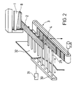
- the support plate 6 it is also possible to provide a row of rods 29 (FIG. 2) which are arranged one behind the other and transversely to the belt transport and can be displaced from the transport path of the belt material 2 by means of a holding rail 30 by means of a working cylinder 31.
- a stop bar 32 ensures that the strip sections 4 are stripped off the bars and can thus fall onto a height-adjustable storage and stacking unit 3 arranged underneath.
- the rods can also be pivotally mounted, and vice versa, the support plate 6 can be slidably held.
- a controllable belt loop path can be provided in front of the cutting device to compensate for the strip feed interrupted during the cutting process.
Landscapes
- Engineering & Computer Science (AREA)
- Chemical & Material Sciences (AREA)
- Composite Materials (AREA)
- Mechanical Engineering (AREA)
- Robotics (AREA)
- Collation Of Sheets And Webs (AREA)
- Reinforced Plastic Materials (AREA)
- Laminated Bodies (AREA)
- Treatment Of Fiber Materials (AREA)
Abstract
Description
- Die Erfindung betrifft eine Vorrichtung zur Herstellung von Bauteilen durch Laminieren von Abschnitten kontinuierlich herangeführten, bandförmigen Materials.
- Die vollmechanisierte Herstellung von Bauteilen aus geschichtetem Bandmaterial, beispielsweise von Rohlingen für Blattfedern aus Faserverbundwerkstoffen erfordert, daß für einen kontinuierlichen Fertigungsablauf alle Herstelleinheiten so aufeinander abgestimmt sind, daß das mit konstanter Geschwindigkeit produzierte Materialband zu Bauteilrohlingen in einer Anzahl pro Zeiteinheit verarbeitet werden kann, die dem Arbeitstakt einer die Rohlinge zusammenfügenden Maschine, beispielsweise einer Presse, entspricht.
- Es war daher die Aufgabe zu lösen, eine Vorrichtung zur Herstellung von Bauteilen aus laminiertem Bandmaterial bereitzustellen, bei der das Schneiden des bandförmigen Materials und das Stapeln der Bandabschnitte zu Bauteilrohlingen an den kontinuierlichen Zulauf des Bandmaterials und an das nachfolgende taktweise Weiterverarbeiten der Rohlinge angepßt sind. Dabei sollen nicht nur unterschiedliche Abschnittslängen innerhalb eines Stapels möglich, sondern auch in allen Dimensionen unterschiedliche Bauteile herstellbar sein.
- Die zur Lösung der Aufgabe entwickelte Vorrichtung besteht aus einer Schneideinrichtung für das Bandmaterial und Auflagemitteln dafür, einer Ausgleichseinrichtung für den während des Schneidvorgangs unterbrochenen Bandvorschub und einer den Auflagemitteln zugeordneten Längenmeßeinrichtung für die abzutrennenden Bandabschnitte, sowie aus einer relativ zu den Auflagemitteln positionierbare Ablage- und Stapeleinheit und einer diesen zugeordneten Überführungseinrichtung für die Bandabschnitte.
- Weitere Einzelheiten und Vorteile der Vorrichtung nach der Erfindung sind an einem in der Zeichnung schematisch dargestellten Ausführungsbeispiel nachfolgend beschrieben.
- Es zeigen
- Figur 1 die Vorrichtung in einer Gesamtansicht
- Figur 2 eine Anordnung von Auflagestäben (Teilansicht)
- Die Vorrichtung besteht im wesentlichen aus zwei Funktionseinheiten (Figur 1): einer Schneideinrichtung 1 für die das kontinuierlich zulaufende bandförmige Material 2, im vorliegenden Ausführungsbeispiel ein Band aus Faserverbundwerkstoff, ein sog. Prepregband, und einer Ablage- und Stapeleinheit 3 für die Banabschnitte 4, die auf eine gemeinsame Grundplatte 5 moniert sind.
- Die Schneideinrichtung 1 weist eine erste, langgestreckte Auflageplatte 6 für das von einer Produktionsanlage zulaufende Materialband 2 auf, zu der in einem Rahmen 7 eine Klemmleiste 8 und ein Messer 9 bewegbar sind. Als Antrieb für die Klemmleiste und das Messer dient ein für derartige Schneidmechaniken üblicher, in der Zeichnung nicht zu sehender Arbeitszylinder.
- Die Länge der abzutrennenden Abschnitte des durch ein Walzenpaar 10 und 11 geförderten und kontinuierlich über die Auflageplatte 6 laufenden Bandes 2 kann über die Umdrehungen der Förderwalzen oder, wie im vorliegenden Ausführungsbeispiel, mit Hilfe einer Längenmeßeinrichtung 12 bestimmt werden, die aus einer in einem Träger 13 gehaltenen, die Auflageplatte einschließenden Signalschranke 14, beispielsweise einer Lichtschranke, besteht. Zum Durchtritt des Lichtstrahls 15 zwischen einer Lichtquelle 16 und einr Photozelle 17 ist die Auflageplatte mit einem Längsschlitz 18 versehen. Sobald die Lichtschranke vom Materialband erreicht wird, schaltet die Photozelle den Antrieb der Klemmleiste 8 und des Messers 9. Während des Schneidvorgangs wird die Schneidvorrichtung mit dem Band mitbewegt. Hierzu ist die Grundplatte 5 in Richtung des Bandtransports bewegbar gelagert, beispielsweise mittels Linearkugellager 19 und mit einem Antrieb, beispielsweise einem Servomotor verbunden, der aktiviert wird, sobald die Klemmleiste das Band berührt.
- Der Träger 13 für die Signalschranke 14 ist auf der Grundplatte 5 längs der Auflageplatte 6 verschiebbar gehalten, beispielsweise durch am Rahmen 7 befestigte, als Längsführungen dienende Stangen 20, um die Länge der Bandabschnitte 4 variieren zu können.
- Auf der gleichen Grundplatte 5 ist die Ablage- und Stapeleinheit 3 montiert, so daß diese auch während der Bewegung der Schneideinrichtung 1 der Auflageplatte 6 zugeordnet bleibt. Sie kann beispielsweise aus einer parallel zur Auflageplatte positionierbaren Aufnahmplatte bestehen, die zum Austragen des fertigen Abschnittstapels, des Bauteilrohlings, mittels einer Übergabestation an eine Transporteinrichtung zu einer Presse angeschlossen ist. Im dargestellten Ausführungsbeispiel ist zur Aufnahme der Bandabschnitte 4 ein seitlich der Auflageplatte 6 angeordnetes und parallel zu dieser bewegbares Förderband 21 mit einem steuerbaren Antrieb 22 vorgesehen, zu dem die Auflageplatte schwenkbar ist und dem im Stapelbereich beidseitig Anschlagplatten 23 für das seitliche Ausrichten der Abschnitte zugeordnet sind. Eine der beiden Anschlagplatten ist seitlich zum Förderband bewegbar. Durch gesteuertes Verfahren des Förderbandes kann für jeden Bandabschnitt die jeweils gewünschte Ablageposition eingestellt werden. Der fertige Abschnittstapel wird dann mit Hilfe des Förderbandes zur Weiterverarbeitung gebracht oder einer weiteren Transporteinrichtung zugeführt.
- Es ist zweckmäßig, die Ablage- und Stapeleinheit 3 mit einer Andruckwalze 24 auszustatten, die in einer längs des Förderbandes 21 ausgedehnten Ausnehmung 25 geführt und mittels eines Linearantriebs reversierend über den Abschnittstapel fahrbar ist. Damit können die Bandabschnitte 4 während des Stapelvorgangs kompaktiert werden. Die Andruckkraft wird durch einen Arbeitszylinder erzeugt.
- Das Gewicht des Abschnittstapels bezogen auf das Flächengewicht des Materialbandes ist ein Maß für die Qualität des hergestellten Bauteils. Zur Messung des Stapelgewichts wird daher das Förderband über eine geeignete Wägeeinrichtung 26 geführt, wobei nach der üblichen Differenzmeßmethode verfahren wird. Geeignete Wägeeinrichtungen stehen im Fachhandel zur Verfügung, so daß auf deren Beschreibung verzichtet werden kann. Eine Gewichtsbestimmung vor Beendigung des Stapelvorgangs erlaubt eine Korrektur durch Weglassen oder Hinzufügen von Abschnitten 4.
- Nach dem Ablegen eines Bandabschnitts schwenkt die Auflageplatte 6 in die Ausgangslage zurück. Ebenso fährt die bis dahin mitbewegte Grundplatte 5 mit sämtlichen Einrichtungen für den nächsten Schneid- und Stapelvorgang in die Ausgangsposition. Dieser Vorgang muß abgeschlossen sein, bevor das inzwischen weitertransportierte Materialband 2 die Lichtschranke 14 erreicht. Für den Fall, daß im Hinblick auf sehr kurze Bandabschnitte mit einem Bandstau gerechnet werden muß, können vor der Schneideinrichtung geeignete Kompensationseinrichtungen, wie Tänzerwalzen oder steuerbare Schleifenpuffer, vorgesehen werden.
- Das Zurückschwenken der Auflageplatte kann entfallen, wenn, wie in der Zeichnung bei einer zweiten Materialbahn 27 zu sehen, eine zweite Auflageplatte 28 in achsensymmetrischer und paralleler Anordnung mit der ersten verbunden ist. Dementsprechend steht nach dem Schwenken der ersten Auflageplatte 6 zum Förderband die zweite Platte 28 für die Aufnahme des nächsten Bandabschnitts bereit.
- Anstelle der Auflageplatte 6 kann auch eine Reihe hintereinander und quer zum Bandtransport angeordneter Stäbe 29 (Figur 2) vorgesehen werden, die über eine Halteschiene 30 mittels eines Arbeitszylinders 31 aus der Transportbahn des Bandmaterials 2 verschiebbar sind. Durch eine Anschlagleiste 32 wird erreicht, daß die Bandabschnitte 4 von den Stäben abgestreift werden und dadurch auf eine darunter angeordnete, höhenverstellbare Ablage- und Stapeleinheit 3 fallen können. Selbstverständlich können die Stäbe auch schwenkbar gelagert sein, sowie auch umgekehrt die Auflageplatte 6 verschiebbar gehalten sein kann.
- Ferner kann anstelle der verschieblichen Lagerung der Schneidvorrichtung und der Auflagemittel 6, 29 zum Ausgleich des während des Schneidvorgangs unterbrochenen Bandvorschubs vor der Schneideinrichtung eine steuerbare Bandschleifenstrecke vorgesehen werden.
- Für die Steuerung der Antriebe der vorstehend beschriebenen Maschineneinheiten können im Fachhandel zur Verfügung stehende Geräte eingesetzt werden, so daß darauf nicht näher eingegangen zu werden braucht.
Claims (10)
Applications Claiming Priority (2)
| Application Number | Priority Date | Filing Date | Title |
|---|---|---|---|
| DE3913836A DE3913836A1 (de) | 1989-04-27 | 1989-04-27 | Vorrichtung zur herstellung von bauteilen aus laminiertem bandmaterial |
| DE3913836 | 1989-04-27 |
Publications (2)
| Publication Number | Publication Date |
|---|---|
| EP0394845A2 true EP0394845A2 (de) | 1990-10-31 |
| EP0394845A3 EP0394845A3 (de) | 1992-01-15 |
Family
ID=6379541
Family Applications (1)
| Application Number | Title | Priority Date | Filing Date |
|---|---|---|---|
| EP19900107441 Withdrawn EP0394845A3 (de) | 1989-04-27 | 1990-04-19 | Vorrichtung zur Herstellung von Bauteilen aus laminiertem Bandmaterial |
Country Status (3)
| Country | Link |
|---|---|
| US (1) | US5096531A (de) |
| EP (1) | EP0394845A3 (de) |
| DE (1) | DE3913836A1 (de) |
Cited By (3)
| Publication number | Priority date | Publication date | Assignee | Title |
|---|---|---|---|---|
| EP0588362A1 (de) * | 1992-09-18 | 1994-03-23 | IVECO FIAT S.p.A. | Verfahren und System zur Bereitung von Kunststoffmaterialladungen zum Beladen einer Formpresse |
| EP2193016A4 (de) * | 2007-09-26 | 2017-05-17 | DIEFFENBACHER GMBH Maschinen- und Anlagenbau | Systeme und verfahren für die schnelle automatisierte herstellung von massgeschneiderten rohlingen aus hochentwickelten verbundwerkstoffen |
| EP4644100A1 (de) * | 2024-05-01 | 2025-11-05 | The Boeing Company | Zusammengesetztes transfersystem mit mehreren zusammengesetzten positionierungsflossen |
Families Citing this family (3)
| Publication number | Priority date | Publication date | Assignee | Title |
|---|---|---|---|---|
| GB9825999D0 (en) * | 1998-11-28 | 1999-01-20 | British Aerospace | A machine for laying up fabric to produce a laminate |
| US20060075623A1 (en) * | 2004-10-13 | 2006-04-13 | Dan Jones | Method of manufacture of metal components |
| DE102014216459A1 (de) * | 2014-08-19 | 2016-02-25 | Bayerische Motoren Werke Aktiengesellschaft | Transportverfahren und -system für biegeschlaffe Materialien |
Family Cites Families (9)
| Publication number | Priority date | Publication date | Assignee | Title |
|---|---|---|---|---|
| US2734843A (en) * | 1952-12-02 | 1956-02-14 | Method of producing honeycomb | |
| US3147166A (en) * | 1961-02-27 | 1964-09-01 | Paul D Friday | Lay-up drum machine |
| FR2041924A5 (de) * | 1969-04-28 | 1971-02-05 | Waldemar Karl | |
| US3819448A (en) * | 1972-04-11 | 1974-06-25 | A Beever | Automatic sheet lining machine |
| US4288280A (en) * | 1979-10-19 | 1981-09-08 | Boston Machine Works Company | Tape applying machine |
| EP0062991B1 (de) * | 1981-04-11 | 1986-09-17 | Gkn Technology Limited | Herstellung von Gegenständen aus zusammengesetztem Material |
| FR2575735B1 (fr) * | 1985-01-04 | 1987-07-10 | Promecan Sisson Lehmann | Dispositif d'empilage de flans |
| JPS6297834A (ja) * | 1985-10-25 | 1987-05-07 | Kawasaki Heavy Ind Ltd | プリプレグ材の積層装置 |
| NL8702487A (nl) * | 1987-10-19 | 1989-05-16 | Dsm Resins Bv | Werkwijze voor de vervaardiging van persprodukten. |
-
1989
- 1989-04-27 DE DE3913836A patent/DE3913836A1/de not_active Withdrawn
-
1990
- 1990-04-19 EP EP19900107441 patent/EP0394845A3/de not_active Withdrawn
- 1990-04-26 US US07/500,938 patent/US5096531A/en not_active Expired - Fee Related
Cited By (4)
| Publication number | Priority date | Publication date | Assignee | Title |
|---|---|---|---|---|
| EP0588362A1 (de) * | 1992-09-18 | 1994-03-23 | IVECO FIAT S.p.A. | Verfahren und System zur Bereitung von Kunststoffmaterialladungen zum Beladen einer Formpresse |
| US5453228A (en) * | 1992-09-18 | 1995-09-26 | Iveco Fiat S.P.A. | Method and system for preparing plastic material loads for supply to a molding press |
| EP2193016A4 (de) * | 2007-09-26 | 2017-05-17 | DIEFFENBACHER GMBH Maschinen- und Anlagenbau | Systeme und verfahren für die schnelle automatisierte herstellung von massgeschneiderten rohlingen aus hochentwickelten verbundwerkstoffen |
| EP4644100A1 (de) * | 2024-05-01 | 2025-11-05 | The Boeing Company | Zusammengesetztes transfersystem mit mehreren zusammengesetzten positionierungsflossen |
Also Published As
| Publication number | Publication date |
|---|---|
| US5096531A (en) | 1992-03-17 |
| DE3913836A1 (de) | 1990-10-31 |
| EP0394845A3 (de) | 1992-01-15 |
Similar Documents
| Publication | Publication Date | Title |
|---|---|---|
| EP0277591B1 (de) | Vorrichtung zur Erzeugung von dünnen Brettern | |
| DE3039293A1 (de) | Vorrichtung zum zufuehren eines einwickelbogens zu einer grossen papierrolle o.dgl. | |
| WO2012104251A1 (de) | Vorrichtung und verfahren zum etikettieren von einzelnen packungen von der packungsunterseite her | |
| DE102008036473B3 (de) | Verfahren und Vorrichtung zum Schneiden von Glasscheiben, Computerprogramm und maschinenlesbarer Träger | |
| EP0164063A2 (de) | Abbundmaschine zum Bearbeiten von Brettern, Kanthölzern und dergleichen | |
| EP0242762B1 (de) | Anordnung zum Zuführen von gestapeltem, blattförmigen Gut zu einer Weiterverarbeitungsstation, insbesondere Schneidstation | |
| DE2428113C2 (de) | Vorrichtung zum einseitig kantengeraden Aufwickeln von Warenbahnen | |
| DE2929973A1 (de) | Vorrichtung zum intermittierenden zufuehren von in verpackungsmaschinen zu verpackenden gegenstaenden | |
| EP0163255A2 (de) | Vorrichtung zum automatischen Beschicken einer Laminierstation | |
| DE2158907B2 (de) | Verfahren und Vorrichtung zum Ausbrechen vorgestanzter Materialstücke aus bogenförmigen Materialbahnen | |
| DE3910041A1 (de) | Bogenanleger zum zufuehren eines aus vereinzelten bogen bestehenden bogenstroms zu einer bogenverarbeitenden maschine | |
| EP0394845A2 (de) | Vorrichtung zur Herstellung von Bauteilen aus laminiertem Bandmaterial | |
| DE102008048831A1 (de) | Fördervorrichtung für eine Verpackungsmaschine | |
| EP0515581B1 (de) | Vorrichtung zum herstellen von wickeln aus federstahlgewirk | |
| EP1018410B1 (de) | Verfahren und Vorrichtung zum Puffern von reihenweise angeordneten Schneidgutstapeln aus blättrigem Gut | |
| EP0489681B1 (de) | Verfahren zum Verschieben kantenbündig aufeinandergestapelter streifen- oder plattenförmiger Werkstücke auf einer reibungsarmen Werkstückauflage, sowie Vorrichtung zur Durchführung dieses Verfahrens | |
| EP2949439B1 (de) | Bearbeitungsvorrichtung und bearbeitungsverfahren | |
| DE8518255U1 (de) | Stütz- und Transportvorrichtung für flächige Werkstücke | |
| DE3503715C2 (de) | ||
| EP0014858B1 (de) | Verfahren und Vorrichtung zum Aufbringen von Aufreissbändchen od.dgl. auf eine Materialbahn | |
| DE3620896A1 (de) | Stuetz- und transportvorrichtung fuer flaechige werkstuecke | |
| DE69801153T2 (de) | Vorrichtung zum zuführen eines filmes zu einer maschine zum verpacken von gegenständen | |
| DE10202462B4 (de) | Vorrichtung zum kontinuierlichen Aufwickeln von Bahnen | |
| DE102018102417A1 (de) | Vorrichtung zum Transportieren und Ausrichten von einem oder mehreren flächigen Bauteilen | |
| DE69124984T2 (de) | Verfahren und Wickelvorrichtung für eine Reifenaufbaumaschine |
Legal Events
| Date | Code | Title | Description |
|---|---|---|---|
| PUAI | Public reference made under article 153(3) epc to a published international application that has entered the european phase |
Free format text: ORIGINAL CODE: 0009012 |
|
| AK | Designated contracting states |
Kind code of ref document: A2 Designated state(s): AT BE CH DE ES FR GB IT LI NL SE |
|
| 17P | Request for examination filed |
Effective date: 19901227 |
|
| PUAL | Search report despatched |
Free format text: ORIGINAL CODE: 0009013 |
|
| AK | Designated contracting states |
Kind code of ref document: A3 Designated state(s): AT BE CH DE ES FR GB IT LI NL SE |
|
| STAA | Information on the status of an ep patent application or granted ep patent |
Free format text: STATUS: THE APPLICATION HAS BEEN WITHDRAWN |
|
| 18W | Application withdrawn |
Withdrawal date: 19920219 |
|
| R18W | Application withdrawn (corrected) |
Effective date: 19920219 |