EP0394877A2 - Zoomobjektivsystem - Google Patents
Zoomobjektivsystem Download PDFInfo
- Publication number
- EP0394877A2 EP0394877A2 EP90107568A EP90107568A EP0394877A2 EP 0394877 A2 EP0394877 A2 EP 0394877A2 EP 90107568 A EP90107568 A EP 90107568A EP 90107568 A EP90107568 A EP 90107568A EP 0394877 A2 EP0394877 A2 EP 0394877A2
- Authority
- EP
- European Patent Office
- Prior art keywords
- lens group
- lens
- focal length
- refraction index
- zoom
- Prior art date
- Legal status (The legal status is an assumption and is not a legal conclusion. Google has not performed a legal analysis and makes no representation as to the accuracy of the status listed.)
- Withdrawn
Links
- 230000003287 optical effect Effects 0.000 claims abstract description 42
- 230000005499 meniscus Effects 0.000 claims abstract description 8
- 230000004075 alteration Effects 0.000 description 75
- 238000010276 construction Methods 0.000 description 15
- 230000035945 sensitivity Effects 0.000 description 7
- 206010010071 Coma Diseases 0.000 description 5
- 201000009310 astigmatism Diseases 0.000 description 5
- 230000002093 peripheral effect Effects 0.000 description 4
- 210000001747 pupil Anatomy 0.000 description 4
- 238000004519 manufacturing process Methods 0.000 description 3
- 238000000034 method Methods 0.000 description 2
- 229920003229 poly(methyl methacrylate) Polymers 0.000 description 2
- 239000004926 polymethyl methacrylate Substances 0.000 description 2
- 239000010453 quartz Substances 0.000 description 2
- VYPSYNLAJGMNEJ-UHFFFAOYSA-N silicon dioxide Inorganic materials O=[Si]=O VYPSYNLAJGMNEJ-UHFFFAOYSA-N 0.000 description 2
- 230000002411 adverse Effects 0.000 description 1
- 230000004323 axial length Effects 0.000 description 1
- 239000011248 coating agent Substances 0.000 description 1
- 238000000576 coating method Methods 0.000 description 1
- 230000003247 decreasing effect Effects 0.000 description 1
- 230000018109 developmental process Effects 0.000 description 1
- 230000000694 effects Effects 0.000 description 1
- 239000011521 glass Substances 0.000 description 1
- 239000000463 material Substances 0.000 description 1
- 239000004033 plastic Substances 0.000 description 1
- 229920003023 plastic Polymers 0.000 description 1
- 230000001105 regulatory effect Effects 0.000 description 1
Images










Classifications
-
- G—PHYSICS
- G02—OPTICS
- G02B—OPTICAL ELEMENTS, SYSTEMS OR APPARATUS
- G02B15/00—Optical objectives with means for varying the magnification
- G02B15/14—Optical objectives with means for varying the magnification by axial movement of one or more lenses or groups of lenses relative to the image plane for continuously varying the equivalent focal length of the objective
- G02B15/16—Optical objectives with means for varying the magnification by axial movement of one or more lenses or groups of lenses relative to the image plane for continuously varying the equivalent focal length of the objective with interdependent non-linearly related movements between one lens or lens group, and another lens or lens group
- G02B15/163—Optical objectives with means for varying the magnification by axial movement of one or more lenses or groups of lenses relative to the image plane for continuously varying the equivalent focal length of the objective with interdependent non-linearly related movements between one lens or lens group, and another lens or lens group having a first movable lens or lens group and a second movable lens or lens group, both in front of a fixed lens or lens group
- G02B15/167—Optical objectives with means for varying the magnification by axial movement of one or more lenses or groups of lenses relative to the image plane for continuously varying the equivalent focal length of the objective with interdependent non-linearly related movements between one lens or lens group, and another lens or lens group having a first movable lens or lens group and a second movable lens or lens group, both in front of a fixed lens or lens group having an additional fixed front lens or group of lenses
- G02B15/17—Optical objectives with means for varying the magnification by axial movement of one or more lenses or groups of lenses relative to the image plane for continuously varying the equivalent focal length of the objective with interdependent non-linearly related movements between one lens or lens group, and another lens or lens group having a first movable lens or lens group and a second movable lens or lens group, both in front of a fixed lens or lens group having an additional fixed front lens or group of lenses arranged +--
-
- G—PHYSICS
- G02—OPTICS
- G02B—OPTICAL ELEMENTS, SYSTEMS OR APPARATUS
- G02B15/00—Optical objectives with means for varying the magnification
-
- G—PHYSICS
- G02—OPTICS
- G02B—OPTICAL ELEMENTS, SYSTEMS OR APPARATUS
- G02B15/00—Optical objectives with means for varying the magnification
- G02B15/14—Optical objectives with means for varying the magnification by axial movement of one or more lenses or groups of lenses relative to the image plane for continuously varying the equivalent focal length of the objective
- G02B15/145—Optical objectives with means for varying the magnification by axial movement of one or more lenses or groups of lenses relative to the image plane for continuously varying the equivalent focal length of the objective having five groups only
- G02B15/1451—Optical objectives with means for varying the magnification by axial movement of one or more lenses or groups of lenses relative to the image plane for continuously varying the equivalent focal length of the objective having five groups only the first group being positive
- G02B15/145125—Optical objectives with means for varying the magnification by axial movement of one or more lenses or groups of lenses relative to the image plane for continuously varying the equivalent focal length of the objective having five groups only the first group being positive arranged +--++
Definitions
- the present invention relates to a compact and high power zoom lens system and, particularly, to a compact zoom lens system having small total length and suitable to use in a video camera or the like.
- a zoom lens can be constituted with a relatively small number of lenses and thus be made compact with high performance by applying aspherical surface to the zoom lens system and suitably regulating focal lengths of lenses constituting the zoom lens.
- a ratio of the total length of the zoom lens to a focal length thereof at wide-angle end is in the order of 11 to 12.
- Such zoom lens is not enough to use in a recent video camera which is much more miniturized.
- An object of the present invention is to provide an improved zoom lens system which includes a minimum number of constituting lenses with good compensation for aberrations and which is high power with zoom ratio being in the order of 6, F number of 1.4 to 1.8 at wide-angle end, a ratio of a total length of the zoom lens to a focal length at wide-angle end being in the order of 7 to 9.
- a zoom lens comprises, from an objective sequentially, a first lens group (1) having a positive refraction index, a second lens group (2) and a third lens group (3) both having negative refraction indices and performing a zooming function by moving along an optical axis, a fourth lens group (4) having a positive refraction index, including a lens at least one surface of which is aspherical and being always stationary, an iris (7) disposed on either the object side or the image side of the fourth lens group, a fifth lens group (5) having a positive refraction index, a quartz plate (6) and an image plane (8), in the order.
- the fifth lens group is of a triplet type including, from the object side, a first lens (9) having a positive refraction index, a second meniscus lens (10) having a negative refraction index and a third lens (11) having a positive refraction index, in the order.
- a zooming is performed by moving the second lens group (2) and the third lens group (3) along an optical axis while keeping an image plane in a fixed position.
- the focusing is performed by moving the whole or a portion of the first lens group (1) or the fifth lens group (5) along the optical axis.
- the fourth lens group (4) serves to make light which diverges from the third lens group (3) and is to be fallen in a center of the image plane afocal or somewhat convergent at an exit side thereof, so that variation of view angle is restricted and height of light passing through the fifth lens group is made as low as possible when the focusing is performed.
- the iris is disposed in the vicinity of the fourth lens group (4) on the object or image plane side thereof so that light to be fallen in a center of the image plane passes through the fourth lens group (4) at a relatively high position. Therefore, the aspherical surface provided in the fourth lens group (4) serves to compensate for aberration of, particularly, light to be fallen in the center portion of the image plane.
- the fifth lens group (5) having the triplet construction serves, together with the aspherical surface of the fourth lens group (4), to sufficiently compensate for various aberrations of a zoom lens whose total length is minimized, with minimum number of lenses. This will be described in detail later.
- the construction according to the present invention permits a good aberration correction with reduced lens gaps or lens thicknesses on the optical axis.
- the aspherical surface provided in the fourth lens group (4) serves to correct spherical aberration mainly and the fifth lens group (5) having the triplet construction corrects mainly peripheral aberrations such as coma and astigmatism.
- the fifth lens group (5) serves to compensate specific aberration such as coma and astigmatism, etc., mainly. Therefore, spherical aberration which can not be corrected by only the fifth lens group (5) is corrected in balance with the aspherical surface provided in the fourth lens group (4), to thereby provide an acceptable aberration compensation as a whole.
- f I is a focal length of the first lens group (1)
- f is a focal length of the second lens group (2)
- f III is a focal length of the third lens group (3)
- f W is a focal length of the whole system at a wide-angle end.
- the zoom lens construction should further satisfy the following condition: 0.13 ⁇ d IV,V / f V ⁇ 0.23 (iv) where d IV,V is a distance on an optical axis between a surface of the fourth lens group (4) closest to the focal plane and a surface of the fifth lens group (5) closest to the object when a photographing distance to the object is infinite, f V is a focal length of the fifth lens group (5).
- the zoom lens of this invention eliminates such problems as above which result from the reduction of total length, by providing the lens system constituted as mentioned hereinbefore and satisfying the conditions (i) to (iii).
- the condition (i) relates to ratio in focal length between the first lens group (1 and the second lens group (2).
- a zoom lens according to the present invention it is effective to make the focal length of the first lens group (1) which has a positive refraction index smaller for minimization of the total length.
- the focal length of the first lens group (1) is made smaller and refraction index larger, the distance along which the second lens group (2) is moved becomes smaller with same zooming ratio and thus it is possible to reduce the distance between them along the optical axis and reduce the total length correspondingly.
- the focal length of the first lens group (1) when the focal length of the first lens group (1) is made small, the height of light passing through the fourth lens group (4) is reduced and so it is possible to make the fourth lens group (4) and the fifth lens group (5) compact.
- the focal length of the first lens group (1) is made too small with respect to that of the second lens group (2), a distance along which the third lens group (3) moves in zooming is increased, causing the total length to be larger, and positioning tolerance of the second lens group (2) on the optical axis is degraded.
- height of light in the first lens group (1), which passes through a center of the iris to the outermost periphery of the image plane, is increased, causing the diameter of the first lens group (1) to be lare and thickness thereof on the optical axis is increased.
- the focal length of the first lens group (1) becomes large with respect to the second lens group (2), so that the total length increases and positioning tolerance of the third lens group (3) on the optical axis is degraded.
- the focal length of the first lens group (1) is too small with respect to that of the second lens group (2), causing positioning tolerance of the second lens group (2) on the optical axis to be severe, and height of light passing through the fourth lens group (4) becomes high, contrarily.
- the condition (ii) relates to ratio in focal length between the first lens group (1) and the third lens group (3).
- it is effective to reduce a focal length and increase refraction index of the third lens group (3) so that an amount of movement of the third lens group (3) in zooming becomes small.
- height of light passing through the third lens group (3) to the fourth lens group (4) becomes undesirably large.
- an amount of movement of the third lens goup (3) in zooming becomes large.
- the condition (iii) defines absolute values in the conditions (i) and (ii). Above the upper limit, the focal length of the first lens group (1) becomes too large with respect to a focal length of a whole zoom lens system, causing the total length to be large. Below the lower limit, the focal length of the first lens group (1) becomes too small, causing the aberration variation and the positioning tolerance on the optical axis to be enhanced.
- the condition (iv) defines the interval on the optical axis between the fourth lens group (4) and the fifth lens group when the latter is used for focusing purpose.
- it is effective to make the fifth lens group (5) as close to the object as possible. Since, as mentioned before, light in the exit side of the fourth lens group (4) is set as substantially afocal, the distance between the fourth lens group (4) and the fifth lens group (5) on the optical axis becomes a dead space for the total length if freedom of aberration correction, etc., is neglected. Therefore, it is possible to shorten the total length by making this distance smaller.
- zooming is performed by moving the second and the third lens groups along an optical axis and focusing is performed by moving the whole or a portion of the first lens group or the fifth lens group along the optical axis.
- the fourth lens group since the fourth lens group has a positive refraction index and causes light diversing from the third lens group to be afocal (light incident on a center of an image plane being in parallel to the optical axis) or somewhat convergent at an output side thereof, height of light incident on the fifth lens group (5) around the center of the image plane thereof is kept substantially constant by which, even the lenses move during the focusing, a variation of focal length of the whole zoom lens system, that is, a variation of image is minimized. Further, with the constant heght of light incident on the fifth lens group, it is possible to minimize a variation of aberration during focusing.
- the first lens group is stationary and, therefore, there is no need of making its diameter large to increase amount of light incident on a peripheral portion of the image plane when it is to be moved forwardly, the diameter of the first lens group can be made smaller correspondingly and thus it is possible to make the whole zoom lens compact.
- the rear focus type zoom lens in which other lens groups than the stationary first lens group which is used to compensate for aberrations of the whole zoom lens system and closer to the image plane is moved along the optical axis, a balance of aberration for the whole zoom lens system is broken when the fifth lens group is so moved, causing a variation of aberration during focusing to be hardly maintain stably. This is also a big problem.
- the fifth lens group is adapted to correct specific aberration corresponding to coma and astigmatism, etc., which affect performance of the zoom lens adversely during focusing, with a balance to the aspherical surface provided in the fourth lens group, so that aberration which can not be corrected by the fifth lens group is corrected as the whole zoom lens.
- the zoom lens in this invention eliminates such problems as above which result from the reduction of total length, by providing the lens system constituted as mentioned hereinbefore and satisfying the conditions (i) to (iv).
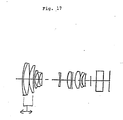
- Fig. 1 is a cross sectional view showing a construction of a zoom lens according to an embodiment of the present invention.
- the zoom lens shown in this figure includes, from an objective side, a first lens group 1 having a positive refraction index, a second lens group 2 and a third lens group 3 which have negative refraction indices and serve to zoom by relatively moving along an optical axis during zooming, while maintaining an image plane 8 always stationary, a fourth lens group 4 having a positive refraction index, being stationary in both zooming and focusing and having at least one surface which is aspherical, an iris 7 disposed on the object side of the fourth lens group 4 or on the exit side of the fourth lens group 4 as shown, a fifth lens group 5 having a positive refraction index, a quartz plane 6 serving as not a lens but a low frequency optical filter and a focal plane 8.
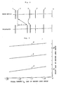
- Fig. 2 shows relative positions of the second lens group and the third lens group to the remaining lens groups of the zoom lens shown in Fig. 1 at wide-angle end and telephoto end in zooming, respectively.
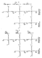
- Figs. 3 to 7 show variations of various parameters when focal lengths of the respective lens groups in Fig. 2 are changed, with zoom ratio, focal length as a whole and distances between the respective lens groups when they are closest to each other during zooming operation being assumed as constant, respectively.
- a variation of shift amount L(mm) of the second lens group 2 is shown when the focal lengths of the first lens group 1 and the second lens group 2 are changed for zooming between wide-angle end and telephoto end (Fig. 2).
- abscissa shows focal length f II (mm) of the second lens group 2.
- a curve a in the same figure is a case where focal length f I of the first lens group 1 is 43.7 mm, b is a case where f I is 39.4 mm and c a case where f I is 35.0 mm, respectively.
- Fig. 4 shows height of light directed to a center of the image plane 8 and passing through the fourth lens group 4 when a ratio of focal distance between the first lens group 1 and the second lens group 2 is changed. Abscissa of this figure shows an absolute value
- the height of light is shown in ratio with unity when focal length f I of the first lens group 1 is 43.7 mm and focal length f II of the second lens group 2 is -12.5 mm.
- a curve a is a case where focal length f I of the first lens group 1 is 43.7 mm
- b is a case where I is 39.4 mm
- c is a case where f I is 35.0 mm.
- Fig. 5 also shows height of light (main light) passing through the first lens group 1, which is to be passed through a center of the iris 7 and fallen on an outermost periphery of the image plane 8, when ratio of focal length between the first lens group 1 and the second lens group 2 is changed.
- Abscissa in this figure shows an absolute value
- Heiht is shown in ratio with unity when focal length f I of the first lens group 1 is 43.7 mm and focal length f II of the second lens group 2 is -12.5 mm.
- a curve a is a case where focal length f I of the first lens group 1 is 43.7 mm
- b is a case where f I is 39.4 mm
- c is a case where f I is 35.0 mm.
- Fig. 6 shows a variation of positioning accuracy of the second lens group 2 on the optical axis at the telephoto end of the zoom lens when ratio of focal length between the first lens group 1 and the second lens group 2 is changed.
- Abscissa in this figure shows ratio in focal length of the first lens group 1 to that of the second lens group 2 and ordinate shows, as amount showing equivalently the postioning accuracy of the second lens group 2 on the optical axis, an amount of shift (referred to sensitivity hereinafter) of light on the image plane 8 when the respective lens groups are moved along the optical axis by a unit distance (1 mm).
- FIG. 7 shows a variation of sensitivity of the third lens group 3 at telephoto end of the zoom lens when the ratio in focal length between the first lens group 1 and the second lens group 2. Abscissa in Fig. 7 shows ratio of focal length of the first lens group 1 to that of the second lens group 2 and ordinate shows the sensitivity of the third lens group 3. From Figs.
- the sensitivity of the second lens group 2 is increased when the focal length of the first lens group 1 is decreased while the ratio of it to that of the second lens group 2 is kept constant and that the sensitivity of the second lens group 2 is little changed and that of the third lens group 3 is reduced considerably, when the focal length of the first lens group 1 is kept constant and the ratio in focal length of the first lens group 1 to the second lens group 2 is reduced.
- a total length is reduced by selecting an interval on an optical axis between the fourth lens group 4 and the fifth lens group 5 as small as possible such that a position of an exit pupil is maintained sufficiently remote from the image plane 8 and that a moving range of the fifth lens group is given when the zoom lens is of the rear focus type.
- the first lens group 1, the second lens group 2 and the third lens group 3 all having focal lengths satisfying the conditions (i) to (iii), the total length is reduced, the lens is made compact and the aberrations are reduced, by making moving amounts of the second lens group 2 and the third lens group 3 in zooming small and by making height of light passing through the first lens group 1 and the fourth lens group 4 as small as possible.
- the various aberrations of the respective lens groups having focal lengths determined to reduce the total length according to the conditions (i) to (iii) are compensated for to acceptable extents.
- the cemented lens of the first lens group 1 is absent, which means that the focal length of the first lens group 1 is made smaller compared with the conventional system, tolerance of lenses constituting the first lens group 1 is degraded. If the cemented lens is separated, astigmatism may be increased in planes of the separated lenses thereof and/or higher order aberrations may be produced, although the freedom of aberration compensation increases.
- Radii of curvature of cemented planes of the cemented lenses of the first lens group 1 is set such that variations of spherical aberration and chromatic aberration of the respective lens groups at telephoto end of the zoom lens in zooming are compensated for and balanced and the lens of the first lens group 1 which is closest to the object is effective to restrict, particularly, spherical aberration and coma aberration and reduce variations thereof in zooming. If such the cemented lens of the second lens group 2 is absent, tolerance of lenses constituting the second lens group 2 becomes severe.
- Radii of curvature of cemented planes of the cemented lenses of the second lens group 2 is set such that, together with the cemented plane of the cemented lens of the first lens group 1, variations of chromatic aberration of the respective lens in, particularly, zooming.
- aberrations of the whole zoom lens system are compensated for and balanced when the system is made comact by reducing the focal length of the first lens group 1.
- the lens of the second lens group 2 which is closest to the object has a configulation determined such that variation of distortion of image due to zooming is compensated for.
- the zoom lens according to the present invention preferrably satisfies the following condition: 200 ⁇
- the condition (v) is to satisfactorily compensate for chromatic aberration of the whole zoom lens system at focal lengths of the respective lens groups set according to the present invention.
- the fifth lens group 5 has the triplet construction including, from the object side, the first lens 9 having a positive refraction index, the second lens 10 having a negative refraction index and the third lens 11 having a positive refraction index, in the order, and compensates, together with the aspherical plane of the fourth lens group 4, for aberration of the whole zoom lens system.
- curvature of image plane is minimized and the freedom of compensation for various aberrations is made larger by making height of light passing through the second lens 10 of the fifth lens group 5 smaller compared with those passing through the first lense 9 and the third lense 11 having positive refraction indices.
- intervals between respective lenses of the triplet lens are very important in compensation for aberrations and that, when its diameter is large, residual aberration such as spherical aberration, etc., becomes large unless a thickness of the whole triplet lens system is increased or the number of lenses is increased. That is, if such intervals are made small and thicknesses of the respective lenses are made small, compensation for aberrations becomes difficult.
- zoom lens according to the present invention by determining focal lengths of the respective lens groups such that height of light incident on the fifth lens group 5 and fallen in the center portion of the image plane becomes as low as possible and by providing at least one aspheric surface in the fourth lens group 4, aberration compensation for the whole zoom lens system is performed in the fifth lens group 5 which has the triplet construction and thickness on the optical axis is minimized.
- a meniscus surface of the second lens 10 of the fifth lens group 5 which has a small radius of curvature, is faced to the image plane to balance spherical aberration, coma aberration and astigmatism aberration produced in the first lens 9 of the fifth lens group 5 by producing them in opposite direction, minimize curvature of the image plane and balance distorsion at wide-angle end and telephoto end of the zoom lens by means of a configulation of the second lens 10 itself.
- the focal length of the first lens 9 of the fifth lens group 5 is set to a small value to some extent so that a difference in height between lights passing through the first and second lenses 9 and 10 can be made relatively large so as to be effective in aberration compensation even if an interval between these lenses is small and the principal point on the side of the object in the fifth lens group 5 is made closer to the iris side so as to reduce the total length.
- the first lens group 1 In the case of the rear focus type zoom lens system in which the focusing is performed by moving not the first lens group 1 but the fifth lens group 5 along the optical axis, the first lens group 1 is always fixed and never moved forwardly. Therefore, it is possible to make a diameter of the first lens group 1 small and to reduce the length thereof on the optical axis if peripheral marginal portions thereof necessary in manufacturing the same is fixed. Further, since the first lens group 1 is stationary in zooming and focusing, there is no need of incorporating a mechanism for moving the first lens group 1 to a lens cylinder structure, causing the whole lens to be compact.
- the variation of view angle in focusing is minimized and the height of light passing through the fifth lens group 5 is made as small as possible by making, on the exit pupil side of the fourth lens group 4, light incident on a center portion of the image plane substantially afocal or somewhat converging.
- r i is a radius of curvature of i-th lens surface from the objective side and positive when a center of curvature of the i-th lens surface is on the side of image plane and negative when it is on the side of the objective.
- d i is a distance on the optical axis between the i-th lens surface and a (i + 1)-th lens surface adjacent thereto.
- n and ⁇ are refraction index and Abbe's number of a j-th lens from the objective side, respectively.
- r1 - r5 relate to the first lens group 1, r6 - r10 to the second lens group 2, r11 and r12 to the third lens group 3, r13 and r14 to the fourth lens group 4, r16- r21 to the fifth lens group 5 and r22 and r23 to the qualtz plate 6, respectively.
- Lens surface having radius of curvature r with an asterisk (*) is aspherical has a shape defined by the following equation including aspheric surface coefficients.
- Z CY2/ ⁇ 1 + ⁇ 1 - (K+1)C2 Y2 ⁇ + A4 Y4 + A6 Y6 + A8 Y8 + A10Y10
- Z is a distance of a point, which is set on a non-spherical plane at a distance Y from the optical axis, from an osculating plane at an apex of an aspherical plane
- C is curvature (1/r) of a reference spherical plane
- K is circular cone constant
- Y height from an optical axis
- A4 to A10 are fourth to tenth order aspherical plane coefficients, respectively.
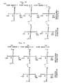
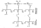
- Figs. 8 to 10 show aberration characteristics of the embodiment 1 mentioned above when photographed an object at a distance ⁇ with focal length of 9.0mm, 32.6mm and 49.6mm, respectively
- Figs. 11 to 13 show aberration characteristics thereof when photographed an object at a distance of 4 m with the same focal lengths
- Figs. 14 to 16 show aberration characteristics when photographed an object at a distance 2 m with the same focal lengths, respectively.
- the ratio of the total length to the focal length at wide-angle end in the numerical embodiment 1 is 8.34.
- d5, d10 and d12 depend upon the focal length f. Examples thereof are shown in the Table 2. Table 2 f(mm) d5 (mm) d10 (mm) d12 (mm) 9.7 0.71 13.99 5.62 34.2 13.90 1.60 4.82 53.4 16.58 2.74 1.00
- the ratio of the total length to the focal length at wide-angle end in the numerical embodiment 2 is 6.75.
- the aspherical surface lens used in the embodiments may be provided by coating a glass lens with a plastic material such as PMMA (polymethylmethacrylate), with similar performance.
- a plastic material such as PMMA (polymethylmethacrylate)
- d5 , d10 and d12 depend upon the focal length f. Examples thereof are shown in the Table 3. Table 3 f(mm) d5 (mm) d10 (mm) d12 (mm) 8.8 0.54 16.32 4.92 31.5 15.42 1.92 4.44 48.5 18.34 2.44 1.00
- d15 and d21 depend upon photographing distance and focal length. Examples thereof are shown in Tables 4 and 5.
- Table 4 photographing distance 4 m
- Table 5 Photographing distance 2 m
- Figs. 8 to 10 show aberration characteristics of the embodiment 1 mentioned above when photographed an object at a distance with focal length of 8.8mm, 31.5mm and 48.5mm, respectively
- Figs. 11 to 13 show aberration characteristics thereof when photographed an object at a distance of 4 m with the same focal lengths
- Figs. 14 to 16 show aberration characteristics when photographed an object at a distance 2 m with the same focal lengths, respectively.
- the ratio of the total length to the focal length at wide-angle end in the numerical embodment 4 is 8.47.
- d5, d10 and d12 depend upon the focal length f. Examples thereof are shown in the Table 6. Table 6 f(mm) d5 (mm) d10 (mm) d12 (mm) 9.0 0.74 12.43 9.25 32.6 15.37 0.51 6.52 50.7 18.10 2.35 1.95
- d15 and d21 depend upon photographing distance and focal length. Examples thereof are shown in Tables 7 and 8.
- Table 7 (Photographing distance 4 m) f(mm) d15 (mm) d21 (mm) 9.0 4.07 5.51 32.6 3.80 5.78 50.7 3.40 6.18
- Table 8 (Photographing distance 2 m) f(mm) d15 (mm) d21 (mm) 9.0 4.05 5.53 32.6 3.53 6.05 50.7 2.75 6.83
- the ratio of the total length to the focal length at wide-angle end in the numerical embodiment 5 is 8.23.
- d5 , d10 and d12 depend upon the focal length f. Examples thereof are shown in the Table 9. Table 9 f(mm) d5 (mm) d10 (mm) d12 (mm) 8.8 0.54 15.93 5.34 18.4 10.28 5.25 6.28 48.4 18.19 2.62 1.00
- d15 and d21 depend upon photographing distance and focal length. Examples thereof are shown in Tables 10 and 11.
- Table 10 (Photographing distance 4 m) f(mm) d15 (mm) d21 (mm) 8.8 3.14 15.02 18.4 3.08 15.08 48.4 2.58 15.58
- Table 11 (Photographing distance 2 m) f(mm) d15 (mm) d21 (mm) 8.8 3.12 15.04 18.4 2.99 15.17 48.4 2.02 16.14
- the ratio of the total length to the focal length at wide-angle end in the numerical embodiment 6 is 8.52.
- d5 , d10 and d12 depend upon focal length f. Examples are shown in the Table 12. Table 12 f(mm) d5 (mm) d10 (mm) d12 (mm) 8.9 0.54 16.00 5.27 32.2 15.42 1.86 4.53 48.9 18.23 2.58 1.00
- d15 and d21 depend upon photographing distance and focal length f. Examples are shown in Tables 13 and 14. Table 13 (Photoraphing distance 4 m) f(mm) d15 (mm) d21 (mm) 8.9 3.14 10.43 32.2 2.89 10.68 48.9 2.53 11.04 Table 14 (Photographing distance 2 m) f(mm) d15 (mm) d21 (mm) 8.9 3.12 10.45 32.2 2.62 10.95 48.9 1.92 11.65 Aspheric plane coefficients in the above embodiment are shown below.
- the ratio of the total length to the focal length at wide-angle end in the numerical embodiment 7 is 7.98.
- d5 , d10 and d12 depend upon focal length f. Examples are shown in the Table 15. Table 15 f(mm) d5 (mm) d10 (mm) d12 (mm) 8.8 1.20 13.31 5.94 33.6 14.13 2.52 3.80 48.4 16.07 3.39 1.00
- d15 and d21 depend upon photographing distance and focal length f. Examples are shown in Tables 16 and 17. Table 16 (Photoraphing distance 4 m) f(mm) d15 (mm) d21 (mm) 8.8 2.84 9.02 33.6 2.58 9.28 48.4 2.28 9.58 Table 17 (Photographing distance 2 m) f(mm) d15 (mm) d21 (mm) 8.8 2.82 9.04 33.6 2.31 9.55 48.4 1.72 10.14 Aspheric plane coefficients in the above embodiment are shown below.
- the ratio of the total length to the focal length at wide-angle end in the numerical embodiment 8 is 7.90.
- d5 , d10 and d12 depend upon focal length f. Examples are shown in the Table 18. Table 18 f(mm) d5 (mm) d10 (mm) d12 (mm) 9.0 0.54 16.00 5.27 32.6 15.42 1.86 4.53 49.6 18.23 2.58 1.00
- d15 and d21 depend upon photographing distance and focal length f. Examples are shown in Tables 19 and 20.
- Table 19 (Photoraphing distance 4 m) f(mm) d15 (mm) d21 (mm) 9.0 3.14 7.27 32.6 2.89 7.52 49.6 2.54 7.87
- Table 20 (Photographing distance 2 m) f(mm) d15 (mm) d21 (mm) 9.0 3.12 7.29 32.6 2.64 7.77 49.6 1.95 8.46 Aspheric plane coefficients in the above embodiment are shown below.
- the ratio of the total length to the focal length a wide-angle end in the numerical embodiment 9 is 8.02.
- d5 , d10 and d12 depend upon focal length f. Examples are shown in the Table 21. Table 21 f(mm) d5 (mm) d10 (mm) d12 (mm) 8.9 0.63 15.54 5.41 32.9 15.56 1.58 4.45 49.0 18.19 2.40 1.00
- d15 and d21 depend upon photographing distance and focal length f. Examples are shown in Tables 22 and 23.
- Table 22 (Photoraphing distance 4 m) f(mm) d15 (mm) d21 (mm) 8.9 3.13 9.87 32.9 2.89 10.11 49.0 2.56 10.44
- Table 23 (Photographing distance 2 m) f(mm) d15 (mm) d21 (mm) 8.9 3.11 9.89 32.9 2.63 10.37 49.0 1.99 11.01 Aspheric plane coefficients in the above embodiment are shown below.
- the ratio of the total length to the focal length at wide-angle end in the numerical embodiment 10 is 8.41.
- d5 , d10 and d12 depend upon focal length f. Examples are shown in the Table 24. Table 24 f(mm) d5 (mm) d10 (mm) d12 (mm) 9.0 0.57 16.80 5.53 32.6 16.19 1.99 4.72 49.6 19.13 2.72 1.05
- d15 and d21 depend upon photographing distance and focal length f. Examples are shown in Tables 25 and 26. Table 25 (Photoraphing distance 4 m) f(mm) d15 (mm) d21 (mm) 9.0 3.98 11.02 32.6 3.74 11.26 49.6 3.40 11.60 Table 26 (Photographing distance 2 m) f(mm) d15 (mm) d21 (mm) 9.0 3.96 11.04 32.6 3.49 11.51 49.6 2.81 12.19 Aspheric plane coefficients in the above embodiment are shown below.
- the ratio of the total length to the focal length at wide-angle end in the numerical embodiment 11 is 8.65.
- the ratio of the total length to the focal length at wide-angle end is in the order of 7 to 9 and aberration for zooming and focusing is well compensated.
- a zoom lens is provided, whose zooming ratio is in the order of 6 and F number is 1.4 to 1.8 and whose ratio of the total length to the focal length at wide-angle end is in the order of 7 to 9 and whose aberration is ell compensated for.
Landscapes
- Physics & Mathematics (AREA)
- General Physics & Mathematics (AREA)
- Optics & Photonics (AREA)
- Nonlinear Science (AREA)
- Lenses (AREA)
Applications Claiming Priority (6)
| Application Number | Priority Date | Filing Date | Title |
|---|---|---|---|
| JP10000989 | 1989-04-21 | ||
| JP100009/89 | 1989-04-21 | ||
| JP204656/89 | 1989-08-09 | ||
| JP204637/89 | 1989-08-09 | ||
| JP1204637A JPH0368909A (ja) | 1989-08-09 | 1989-08-09 | ズームレンズ |
| JP1204656A JPH0339919A (ja) | 1988-12-09 | 1989-08-09 | ズームレンズ |
Publications (2)
| Publication Number | Publication Date |
|---|---|
| EP0394877A2 true EP0394877A2 (de) | 1990-10-31 |
| EP0394877A3 EP0394877A3 (de) | 1991-10-30 |
Family
ID=27309111
Family Applications (1)
| Application Number | Title | Priority Date | Filing Date |
|---|---|---|---|
| EP19900107568 Withdrawn EP0394877A3 (de) | 1989-04-21 | 1990-04-20 | Zoomobjektivsystem |
Country Status (3)
| Country | Link |
|---|---|
| US (1) | US5048939A (de) |
| EP (1) | EP0394877A3 (de) |
| KR (1) | KR930001536B1 (de) |
Families Citing this family (7)
| Publication number | Priority date | Publication date | Assignee | Title |
|---|---|---|---|---|
| JPH03288813A (ja) * | 1990-04-06 | 1991-12-19 | Hitachi Ltd | ズームレンズ |
| JP2808815B2 (ja) * | 1990-04-19 | 1998-10-08 | 株式会社ニコン | 内部合焦式望遠ズームレンズ |
| US5565919A (en) * | 1992-03-12 | 1996-10-15 | Hitachi, Ltd. | Video camera/VTR and camera station with opto-electronic link between camera/VTR and camera station |
| KR100234248B1 (ko) * | 1995-06-07 | 1999-12-15 | 윤종용 | 광픽업용 2위치 결상 대물렌즈 |
| KR100234250B1 (ko) * | 1995-06-30 | 1999-12-15 | 윤종용 | 동배율 가변초점을 갖는 렌즈장치 및 이를 이용한 광픽업 |
| JP4734827B2 (ja) * | 2003-11-28 | 2011-07-27 | 株式会社日立製作所 | 投写光学ユニット |
| US9613815B2 (en) * | 2014-11-24 | 2017-04-04 | Ultratech, Inc. | High-efficiency line-forming optical systems and methods for defect annealing and dopant activation |
Family Cites Families (2)
| Publication number | Priority date | Publication date | Assignee | Title |
|---|---|---|---|---|
| JPS6193423A (ja) * | 1984-10-12 | 1986-05-12 | Minolta Camera Co Ltd | 大口径比ズ−ムレンズ |
| US4812024A (en) * | 1987-05-11 | 1989-03-14 | Canon Kabushiki Kaisha | Zoom lens |
-
1990
- 1990-04-17 US US07/510,284 patent/US5048939A/en not_active Expired - Fee Related
- 1990-04-20 EP EP19900107568 patent/EP0394877A3/de not_active Withdrawn
- 1990-04-20 KR KR1019900005556A patent/KR930001536B1/ko not_active Expired - Fee Related
Also Published As
| Publication number | Publication date |
|---|---|
| US5048939A (en) | 1991-09-17 |
| EP0394877A3 (de) | 1991-10-30 |
| KR900016775A (ko) | 1990-11-14 |
| KR930001536B1 (ko) | 1993-03-04 |
Similar Documents
| Publication | Publication Date | Title |
|---|---|---|
| US6597513B2 (en) | Zoom lens system | |
| JP3103166B2 (ja) | 射出瞳の遠いマクロレンズ | |
| US5585966A (en) | Zoom lens with vibration reduction function | |
| US5329402A (en) | Wide-angle zoom lens | |
| JPH09179026A (ja) | 変倍光学系 | |
| JP4447680B2 (ja) | ズームレンズ | |
| JP3365835B2 (ja) | コンパクトな3群ズームレンズ | |
| US6580565B2 (en) | Zoom lens system | |
| JPH10206737A (ja) | 小型なズーム光学系 | |
| JP3018723B2 (ja) | ズームレンズ | |
| JP4101992B2 (ja) | 小型高変倍広角ズームレンズ | |
| JP3449427B2 (ja) | 小型で広角なズームレンズ | |
| JPH11167061A (ja) | 撮影光学系 | |
| US6002526A (en) | Zoom lens system | |
| JPH07199070A (ja) | ズームレンズ | |
| US4591234A (en) | Rear focus conversion lens | |
| JPH11174328A (ja) | ズームレンズ | |
| JPH1010423A (ja) | 近赤外光束透過防止レンズ系 | |
| JP3184581B2 (ja) | ズームレンズ | |
| EP0394877A2 (de) | Zoomobjektivsystem | |
| JPH11142737A (ja) | 変倍レンズ系 | |
| JPH1048523A (ja) | ズームレンズ | |
| US6657792B2 (en) | Zoom lens system | |
| JP2828263B2 (ja) | コンパクトカメラ用高変倍ズームレンズ | |
| JPH0694997A (ja) | 高変倍で広角なズームレンズ |
Legal Events
| Date | Code | Title | Description |
|---|---|---|---|
| PUAI | Public reference made under article 153(3) epc to a published international application that has entered the european phase |
Free format text: ORIGINAL CODE: 0009012 |
|
| 17P | Request for examination filed |
Effective date: 19900420 |
|
| AK | Designated contracting states |
Kind code of ref document: A2 Designated state(s): DE FR GB |
|
| PUAL | Search report despatched |
Free format text: ORIGINAL CODE: 0009013 |
|
| AK | Designated contracting states |
Kind code of ref document: A3 Designated state(s): DE FR GB |
|
| STAA | Information on the status of an ep patent application or granted ep patent |
Free format text: STATUS: THE APPLICATION HAS BEEN WITHDRAWN |
|
| 18W | Application withdrawn |
Withdrawal date: 19920902 |