EP0394879A2 - Elektronisches Informationsgerät - Google Patents
Elektronisches Informationsgerät Download PDFInfo
- Publication number
- EP0394879A2 EP0394879A2 EP90107574A EP90107574A EP0394879A2 EP 0394879 A2 EP0394879 A2 EP 0394879A2 EP 90107574 A EP90107574 A EP 90107574A EP 90107574 A EP90107574 A EP 90107574A EP 0394879 A2 EP0394879 A2 EP 0394879A2
- Authority
- EP
- European Patent Office
- Prior art keywords
- main body
- electronic information
- display
- information equipment
- keyboard
- Prior art date
- Legal status (The legal status is an assumption and is not a legal conclusion. Google has not performed a legal analysis and makes no representation as to the accuracy of the status listed.)
- Granted
Links
Images




Classifications
-
- G—PHYSICS
- G06—COMPUTING OR CALCULATING; COUNTING
- G06F—ELECTRIC DIGITAL DATA PROCESSING
- G06F1/00—Details not covered by groups G06F3/00 - G06F13/00 and G06F21/00
- G06F1/16—Constructional details or arrangements
- G06F1/1613—Constructional details or arrangements for portable computers
- G06F1/1615—Constructional details or arrangements for portable computers with several enclosures having relative motions, each enclosure supporting at least one I/O or computing function
- G06F1/1616—Constructional details or arrangements for portable computers with several enclosures having relative motions, each enclosure supporting at least one I/O or computing function with folding flat displays, e.g. laptop computers or notebooks having a clamshell configuration, with body parts pivoting to an open position around an axis parallel to the plane they define in closed position
-
- G—PHYSICS
- G06—COMPUTING OR CALCULATING; COUNTING
- G06F—ELECTRIC DIGITAL DATA PROCESSING
- G06F1/00—Details not covered by groups G06F3/00 - G06F13/00 and G06F21/00
- G06F1/16—Constructional details or arrangements
- G06F1/1613—Constructional details or arrangements for portable computers
- G06F1/1615—Constructional details or arrangements for portable computers with several enclosures having relative motions, each enclosure supporting at least one I/O or computing function
- G06F1/1616—Constructional details or arrangements for portable computers with several enclosures having relative motions, each enclosure supporting at least one I/O or computing function with folding flat displays, e.g. laptop computers or notebooks having a clamshell configuration, with body parts pivoting to an open position around an axis parallel to the plane they define in closed position
- G06F1/162—Constructional details or arrangements for portable computers with several enclosures having relative motions, each enclosure supporting at least one I/O or computing function with folding flat displays, e.g. laptop computers or notebooks having a clamshell configuration, with body parts pivoting to an open position around an axis parallel to the plane they define in closed position changing, e.g. reversing, the face orientation of the screen with a two degrees of freedom mechanism, e.g. for folding into tablet PC like position or orienting towards the direction opposite to the user to show to a second user
-
- G—PHYSICS
- G06—COMPUTING OR CALCULATING; COUNTING
- G06F—ELECTRIC DIGITAL DATA PROCESSING
- G06F1/00—Details not covered by groups G06F3/00 - G06F13/00 and G06F21/00
- G06F1/16—Constructional details or arrangements
- G06F1/1613—Constructional details or arrangements for portable computers
- G06F1/1633—Constructional details or arrangements of portable computers not specific to the type of enclosures covered by groups G06F1/1615 - G06F1/1626
- G06F1/1662—Details related to the integrated keyboard
- G06F1/1669—Detachable keyboards
Definitions
- the invention relates generally to electronic information equipments, and more particularly, to an electronic information equipment constructed so as to accommodate separable entry means sandwiched between a main body and display means.
- FIGs. 1 and 2 are side views showing an electronic information equipment disclosed in Japanese Patent Laying-Open No. 59-91524 for example.
- a display 31 is closed onto a main body 32 when not in use.
- the electronic information equipment will be brought in a use position by raising the display 31 which covers a keyboard 30 during the time when not in use.
- Figs. 3 and 4 are side views showing the electronic information equipment disclosed in this laid open application. It can be seen from Fig.
- a liquid crystal display 33 is rotatably attached to a longitudinal main body 32.
- a keyboard 34 is placed before the liquid crystal display 33 when in use. Referring to Fig. 4, the liquid crystal display 33 and the keyboard 34 are fitted upright in turn to be integrally accommodated.
- FIG. 5 The situation as shown in Fig. 5 is considered in which an electronic information equipment disclosed in Japanese Utility Model Laying-Open No. 60-148632 is placed on a desk 35 where two desks 35 and 36 are disposed to face each other.
- the electronic information equipment since the electronic information equipment is accommodated vertically when not in use, there was a problem that the field of vision of user A would be blocked so that the equipment could become an obstacle when speaking to the opposite occupant B.
- FIGs. 7 and 8 are perspective views showing the appearance of the electronic information equipment disclosed in this laid open application, with the keyboard set to be used and with the keyboard housed, respectively.
- a keyboard 43 is accommodated sandwiched between a main body 41 and a display portion 42.
- the keyboard 43 is placed before the main body 41 with a key top portion 43a facing upward as shown in Fig. 7.
- the display portion 42 is rotated in the arrow C direction at a predetermined angle to the main body 41.
- the keyboard 43 is connected to the main body 41 by a connector portion 45 and a connection cable 44.
- the keyboard 43 fits into an accommodating portion 41a of the main body 41 when not in use.
- the height of this electronic information equipment is considerably low compared to that shown in Fig. 4 when not in use, so the front field of vision is not blocked.
- An object of the present invention is to provide an electronic information equipment that can be used without having to place a main body and a display in front of an operator.
- An electronic information equipment in accordance with the present invention is constructed to accommodate an entry means sandwiched between a main body and a display means, and comprises a main body, an entry means, a display means, a rotating means and a tilting means.
- the main body has an installation plane that will contact a predetermined location for setting down the main body.
- the entry means is separable from the main body and is used to input information.
- the display means is movably attached to the main body with the display face having a predetermined position relative to the installation plane for displaying information.
- the rotating means is for rotating the display means about the axis which intersects with the installation plane.
- the tilting means is for supporting the display means at a position where the display face is at an arbitrary angle with respect to the installation plane.
- the rotating means comprises a rotating body and an accommodating member.
- the rotating body rotates about the axis which intersects the installation plane.
- the accommodating member rotatably receives the rotating body and is mounted to the main body.
- the tilting means comprises a shaft portion and a supporting member.
- the shaft portion is located along an axis which intersects the above axis at an approximately right angle.
- the supporting member is rotatably attached around the shaft portion and is fixed to the display means.
- a coupling member is also provided to couple the rotating body and the shaft portion.
- the supporting member is attached to the shaft portion by an energizing member.
- the entry means has a main surface in which a number of key tops are provided, and may comprise a movable member which protrudes outwards from the main surface and retracts inwardly, and a moving means to move the movable member.
- the main body may comprise an engaging member provided at a corresponding position to engage the outwardly protruding movable member when the entry means is placed over the main body.
- the display means is rotated above the installation plane with respect to the main body by rotating means. Also, the display means is supported at a position with the display face intersecting the installation plane at an arbitrary angle by the tilting means. Therefore, the display means can be held at an arbitrary angle to the operator and at an arbitrary tilting position. This eliminates the necessity of placing the main body of the electronic information equipment in front of the operator when in use to allow the effective wide use of the desk where the equipment is located.
- a main body 1 incorporating a control device, floppy disc devices, etc. supports a display 2.
- the display 2 is rotatably supported at an arbitrary angle vertically and horizontally by a supporting device 3 provided in the main body 1.
- the display 2 is comprised of a liquid crystal display device.
- the display 2 When not in use, the display 2 is accommodated parallel to the main body 1 with the display face 2a downwards. There is a predetermined space between the main body 1 and the display 2.
- the keyboard 4 fits into this space with the key top face 4a downwards when not in use.
- the display 2 is rotated from the unused position of Fig. 9 to a counterclockwise direction indicated by arrow V shown in Fig. 10, followed by a horizontal rotation in the direction shown by arrow H to provide a use position as shown in Fig. 11.
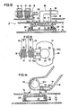
- the supporting device 3 has a base board 8 secured by bosses 7 formed on a lower cabinet 1b.
- a cylindrical cover member 9 having openings in the top central portion and in the bottom is fixed.
- a rotating body 10 is accommodated in the interior of the cover member 9.
- the rotating body 10 is formed in a cylindrical configuration with an open bottom.
- Four bosses 11 formed on the top surface of the rotating body 10 protrudes above an upper cabinet 1a through the upper opening 12 of the cover member 9 and an opening 13 formed in the upper cabinet 1a.
- a coupling member 14 is fixed to the bosses 11 of the rotating body and couples the rotating body 10 and a shaft 15.
- the coupling member 14 comprises a roughly circular bottom and integrally formed right and left upright pieces 14a, 14b.
- the left side upright piece 14a is bent to an inverted L-shape.
- the shaft 15 is fixed to the upright piece 14a.
- a supporting plate 16 is rotatably attached to the shaft 15 via coil springs 17.
- the tilting means comprises the shaft 15, the supporting plate 16 and the coil springs 17.
- the supporting plate 16 is secured by bosses 19 formed on the cabinet 18 which accommodates the display. Accordingly, the supporting plate 16 rotates about the shaft 15 when the display 2 (cabinet 18) is rotated in the vertical direction.
- the display 2 is held at an arbitrary rotating position. Also, by rotating the display 2 in the horizontal direction, the rotating body 10 rotates via a coupling member 14.
- the display 2 can be rotated at an arbitrary angle in a horizontal direction with respect to the main body 1. As shown in Fig. 15, this allows the installment of the main body 1 of the electronic information equipment on a side table 20 and rotation of the display 2 to the direction of the operator A.
- the keyboard 4 is placed in front of the operator A on top of the desk 21.
- the main body 1 is provided aside the operator A, while the display 2 is held at an easy-to-see position for the operator A.
- the necessity to place the main body in front of the operator is eliminated to effectively utilize the desk top widely.
- the view in front of the operator A is not blocked and the display can always be held at an easy-to-see position.
- the keyboard 4 may be placed over the display 2 to effectively utilize the top of the desk, as shown in Fig. 16. Also, when the electronic information equipment is not to be used for a long time, the display 2 and the keyboard 4 may be accommodated in the main body 1 as shown in Fig. 9, to effectively use the top of the desk.
- the main body 1 and the display 2 are connected by a cord 24 inserted from the opening 22 of the coupling member 14 into the opening 23 of the upright piece 14b, as shown in Figs. 12 and 13.
- a groove 25 is formed at the periphery of the rotating body 10 for a predetermined range.
- a stopper pin 26 which protrudes inwardly from the cover member 9 is provided. By engaging the stopper pin 26 at a predetermined rotating position in the groove 25, the rotating body 10 is restricted to rotate within a predetermined range. This will prevent the connection cord 24 from being twisted and disconnected by the excessive rotation of the display 2.
- the keyboard 4 provided with a number of key tops is connected to the main body 1 by the cord 5, as shown in Fig. 11.
- a projection 107 is provided in the front central portion of the keyboard 4, as shown in Fig. 19.
- the projection 107 is constructed so as to travel between a state protruding from the surface of the keyboard and a state retracted inwardly of the keyboard, as shown in Figs. 20 and 22.
- the projection 107 is moved by a lever 106 provided on the back surface of the keyboard 4 as shown in Fig. 21.
- An accommodating projection 109 is provided in the main body 1 as shown in Figs. 17 and 18 to accommodate the projection 107 when the keyboard 4 is placed over the main body 1.
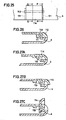
- the projection 107 moves up and down by the operation of the lever 106 provided on the back surface 4c of the keyboard 4 by the mechanism shown in Figs. 23A and 23B. That is, the projection 107 and the lever 106 are coupled by parallel links 108.
- the projection 107 is withdrawn inside the keyboard and its surface flush with the surface of the keyboard 4b, as shown in Fig. 23A.
- the projection 107 rises to be set at a protruded state from the keytop surface 4a as shown in Fig. 23B.
- the protruding projection 107 may be accommodated in the accommodating projection 109 provided on the surface of the main body 1.
- the accommodating projection 109 has one open end formed in a configuration to accommodate the projection 107.
- the projection 107 of the keyboard 4 will obstruct the key operation, it will be in the withdrawn position as shown in Fig. 23A.
- the projection 107 is raised by operating the lever 106 provided on the back surface 4c of the keyboard 4 as shown in Fig. 23B.
- the keyboard 4 is placed over the display 2 as shown in Fig. 16, wherein the key top surface 4a faces the display face 2a of the display 2. Since a gap is formed between the key top surface 4a and the display face 2a by the projection 107, the key top surface 4a will not directly contact the display face 2a to avoid the damage of the display face 2a.
- a stopper projection 115 is provided on the lower side of the display 2 to prevent the keyboard 4 from sliding off the tilting display 2.
- the display 2 When the usage of the equipment is thoroughly completed and the keyboard is to be accommodated, the display 2 is rotated to the position shown in Fig. 10 from the position in Fig. 11, followed by the protrusion of the projection 107 of the keyboard 4 in the manner as previously described. Then, the keyboard 4 is placed over the main body 1 with the key top surface 4a downwards as shown in Fig. 10. The keyboard 4 is positioned so that the projection 107 of the keyboard 4 may engage the accommodating projection 109 of the main body 1. After placing the keyboard 4, the display 2 is rotated in the clockwise direction from the position shown in Fig. 10 to the accommodating state shown in Fig. 9.
- the displacement of the keyboard 4 will be prevented and secured during its storage. Furthermore, the key tops will not be damaged because the key top surface 4a is not in direct contact with the main body 1 due to the projection 107. In the above explained manner, the protection of the key tops as well as the fixation of the keyboard is achieved during the accommodating position.
- the projection of the keyboard 4 may be moved by rotation.
- a half-circular rotating member 110 is provided on the surface 4b of the keyboard. By manually turning the rotating member 110, the rotating member 110 rotates about a shaft 110a for displacement between the two positions shown in Figs. 24A and 24B.
- the projection of the keyboard may also be moved by the hereinafter described rotating means.
- a rotating shaft 113 is inserted in an oval-shaped aperture 112 of two supporting pieces 111 formed integrally with the cabinet of keyboard 4.
- a rotating projection 114 is slidably and rotatably formed with respect to the cabinet of the keyboard 4.
- the shaft 113 of the rotating projection 114 is located on the left side of the oval-shaped aperture 112 as shown in Figs. 26 and 27A.
- the rotating projection 114 is slid to the right direction in the figure as shown in Fig. 27B.
- the rotating projection 114 will protrude above the keyboard 4 by rotating in the counterclockwise direction about the shaft 113.
- the necessity to place the main body in front of the operator is eliminated by rotatably supporting the display in vertical and horizontal directions to the main body to permit the wide effective use of the desk which serves as the installation plane.
- the key tops will be protected when the keyboard is placed on the main body for accommodation by providing a protrudable projection in the keyboard as well as providing an accommodating projection in the main body to receive the projection in the keyboard.
- the protection of the display is also achieved when the keyboard is temporarily placed on the display.
Landscapes
- Engineering & Computer Science (AREA)
- Computer Hardware Design (AREA)
- Theoretical Computer Science (AREA)
- Physics & Mathematics (AREA)
- Human Computer Interaction (AREA)
- General Engineering & Computer Science (AREA)
- General Physics & Mathematics (AREA)
- Mathematical Physics (AREA)
- Casings For Electric Apparatus (AREA)
- Devices For Indicating Variable Information By Combining Individual Elements (AREA)
Applications Claiming Priority (6)
| Application Number | Priority Date | Filing Date | Title |
|---|---|---|---|
| JP1989048135U JPH0720756Y2 (ja) | 1989-04-24 | 1989-04-24 | 電子機器 |
| JP48135/89 | 1989-04-24 | ||
| JP53649/89 | 1989-05-10 | ||
| JP1117080A JP2735874B2 (ja) | 1989-05-10 | 1989-05-10 | 表示器付電子機器 |
| JP117080/89 | 1989-05-10 | ||
| JP5364989U JPH02145427U (de) | 1989-05-10 | 1989-05-10 |
Publications (3)
| Publication Number | Publication Date |
|---|---|
| EP0394879A2 true EP0394879A2 (de) | 1990-10-31 |
| EP0394879A3 EP0394879A3 (de) | 1991-03-06 |
| EP0394879B1 EP0394879B1 (de) | 1994-09-14 |
Family
ID=27293201
Family Applications (1)
| Application Number | Title | Priority Date | Filing Date |
|---|---|---|---|
| EP90107574A Expired - Lifetime EP0394879B1 (de) | 1989-04-24 | 1990-04-20 | Elektronisches Informationsgerät |
Country Status (5)
| Country | Link |
|---|---|
| US (1) | US5034858A (de) |
| EP (1) | EP0394879B1 (de) |
| AU (1) | AU623762B2 (de) |
| CA (1) | CA2015078C (de) |
| DE (1) | DE69012400T2 (de) |
Cited By (4)
| Publication number | Priority date | Publication date | Assignee | Title |
|---|---|---|---|---|
| EP0626632A1 (de) * | 1993-05-14 | 1994-11-30 | Sharp Kabushiki Kaisha | Tragbarer Rechner mit Tastatur oder Stift zur Dateneingabe |
| GB2321982A (en) * | 1997-02-07 | 1998-08-12 | Fujitsu Icl Computers Oy | Positioning notebook computer screen to facilitate use with external keyboard |
| WO2001033321A1 (de) * | 1999-10-29 | 2001-05-10 | Wincor Nixdorf Gmbh & Co. Kg | Bildschirmarbeitsplatz für tisch- und wandmontage |
| WO2011091790A3 (de) * | 2010-02-01 | 2011-11-17 | Constin Gmbh | Tragbare kommunikationsvorrichtung |
Families Citing this family (43)
| Publication number | Priority date | Publication date | Assignee | Title |
|---|---|---|---|---|
| USD328288S (en) | 1989-08-29 | 1992-07-28 | Kabushiki Kaisha Toshiba | Electronic computer |
| USD330197S (en) | 1989-08-30 | 1992-10-13 | Kabushiki Kaisha Toshiba | Electronic computer |
| JPH0394318A (ja) * | 1989-09-07 | 1991-04-19 | Toshiba Corp | 携帯用電子機器 |
| DE4008541C1 (de) * | 1990-03-16 | 1991-11-21 | Siemens Nixdorf Informationssysteme Ag, 4790 Paderborn, De | |
| US5268817A (en) * | 1990-04-27 | 1993-12-07 | Kabushiki Kaisha Toshiba | Portable computer with keyboard and having display with coordinate input tablet rotatably mounted to face either toward or away from keyboard when closed over keyboard |
| EP0454120A3 (de) * | 1990-04-27 | 1992-12-30 | Kabushiki Kaisha Toshiba | Tragbarer Rechner mit Tastatur und Koordinateneingabetablett |
| USD343831S (en) | 1990-05-25 | 1994-02-01 | Spoeth Carl R | Combined housing and display screen for laptop computer and CD ROM terminal |
| USD339330S (en) | 1990-12-04 | 1993-09-14 | International Business Machines Corp. | Personal computer with disassociated keyboard |
| US5260884A (en) * | 1991-07-17 | 1993-11-09 | Jonathan Stern | Brief case having integral computer |
| US5440502A (en) * | 1991-12-26 | 1995-08-08 | Dell Usa, L.P. | Stylus operable computer with wireless keyboard in storage bay |
| JPH0559516U (ja) * | 1992-01-08 | 1993-08-06 | ブラザー工業株式会社 | 文書作成装置 |
| JPH05189084A (ja) * | 1992-01-10 | 1993-07-30 | Toshiba Corp | 小形電子機器 |
| USD349694S (en) | 1992-02-27 | 1994-08-16 | Shimadzu Corporation | Portable computer |
| US5247285A (en) * | 1992-03-06 | 1993-09-21 | Everex Systems, Inc. | Standup portable personal computer with detachable wireless keyboard and adjustable display |
| USD345347S (en) | 1992-04-28 | 1994-03-22 | International Business Machines Corp. | Portable computer |
| US5335142A (en) * | 1992-12-21 | 1994-08-02 | Ast Research, Inc. | Portable computer display tilt/swivel mechanism |
| US5604688A (en) * | 1993-01-13 | 1997-02-18 | Tomax Enterprises, Inc. | Message display calculator |
| USD356071S (en) | 1993-02-22 | 1995-03-07 | Sanyo Electric Co., Ltd. | Computer |
| USD357465S (en) | 1993-04-22 | 1995-04-18 | Kabushiki Kaisha Toshiba | Electronic computer |
| USD361323S (en) | 1993-07-23 | 1995-08-15 | International Business Machines Corporation | Personal computer housing |
| USD361322S (en) | 1993-07-23 | 1995-08-15 | International Business Machines Corporation | Portable personal computer |
| AU2060895A (en) * | 1994-03-02 | 1995-09-18 | Jeffrey P. Lane | Modular, reconfigurable devices |
| JP3467362B2 (ja) * | 1996-01-08 | 2003-11-17 | 富士通株式会社 | 情報処理装置 |
| US5842672A (en) * | 1996-06-07 | 1998-12-01 | Ergotron, Inc. | Mounting system for flat panel display, keyboard and stand |
| US8183998B2 (en) | 1996-12-16 | 2012-05-22 | Ip Holdings, Inc. | System for seamless and secure networking of implantable medical devices, electronic patch devices and wearable devices |
| US7929950B1 (en) | 1996-12-16 | 2011-04-19 | Ip Holdings, Inc. | Dynamically configurable IP based wireless device and wireless networks |
| US6169789B1 (en) | 1996-12-16 | 2001-01-02 | Sanjay K. Rao | Intelligent keyboard system |
| US5800028A (en) * | 1997-02-27 | 1998-09-01 | Communications Technology Corporation | Terminal block hinge mechanism |
| US6006243A (en) * | 1997-05-30 | 1999-12-21 | International Business Machines Corporation | Foldable personal computer with detachable cover section |
| US5926364A (en) * | 1997-05-30 | 1999-07-20 | International Business Machines Corporation | Tri-fold personal computer with touchpad and keyboard |
| KR100284300B1 (ko) | 1998-10-16 | 2001-03-02 | 윤종용 | 휴대형 컴퓨터 |
| US10728381B2 (en) * | 1999-06-04 | 2020-07-28 | Raman K. Rao | Reconfigurable mobile device interfaces supporting authenticated high quality video, audio, TV and multimedia services |
| KR100553677B1 (ko) | 1999-06-11 | 2006-02-24 | 삼성전자주식회사 | 커버를 지지하기 위한 구조를 갖는 휴대용 컴퓨터 |
| US6256192B1 (en) * | 1999-08-09 | 2001-07-03 | Packard Bell Nec, Inc. | Accordion-fold laptop computer |
| CA101254S (en) | 2002-07-24 | 2004-04-07 | Toshiba A T A Toshiba Corp Kk | Electronic computer |
| AU151439S (en) | 2002-07-24 | 2003-04-15 | Toshiba Kk | An electronic computer |
| US8965460B1 (en) | 2004-01-30 | 2015-02-24 | Ip Holdings, Inc. | Image and augmented reality based networks using mobile devices and intelligent electronic glasses |
| US11455799B2 (en) | 2004-01-30 | 2022-09-27 | Airspace Reality | Image networks for mobile communication |
| US10140514B1 (en) | 2004-01-30 | 2018-11-27 | Ip Holdings, Inc. | Capturing and sharing images with mobile device users including for a limited duration of time |
| CN102985891B (zh) | 2010-05-20 | 2016-05-25 | 萨尔曼·萨基德 | 一种用于平板设备及键盘的组合式支架保护套 |
| US10142496B1 (en) | 2013-01-26 | 2018-11-27 | Ip Holdings, Inc. | Mobile device image capture and image modification including filters, superimposing and geofenced comments in augmented reality |
| US9300645B1 (en) | 2013-03-14 | 2016-03-29 | Ip Holdings, Inc. | Mobile IO input and output for smartphones, tablet, and wireless devices including touch screen, voice, pen, and gestures |
| KR102736199B1 (ko) * | 2023-03-08 | 2024-11-28 | 엘지전자 주식회사 | 디스플레이 디바이스 |
Family Cites Families (9)
| Publication number | Priority date | Publication date | Assignee | Title |
|---|---|---|---|---|
| US2617619A (en) * | 1951-04-03 | 1952-11-11 | Versen Kurt | Supporting arm for electrical fixtures |
| US4305266A (en) * | 1979-12-21 | 1981-12-15 | Lockwood Robert G | Locking apparatus for portable devices |
| US4571456B1 (en) * | 1982-10-18 | 1995-08-15 | Grid Systems Corp | Portable computer |
| JPS60148682A (ja) * | 1984-01-13 | 1985-08-05 | Matsushita Electric Works Ltd | 抵抗溶接装置 |
| JPS60148632A (ja) * | 1984-01-14 | 1985-08-05 | Shinichi Tsugawa | 格子などの縦材と横材の交叉結合方法 |
| JPH0246964B2 (ja) * | 1984-01-31 | 1990-10-18 | Matsushita Electric Ind Co Ltd | Keitaigatadenshisochi |
| JPS62201826A (ja) * | 1986-02-28 | 1987-09-05 | Meiji Milk Prod Co Ltd | 血小板凝集抑制剤 |
| JPS62201826U (de) * | 1986-06-13 | 1987-12-23 | ||
| JPS63271511A (ja) * | 1987-01-15 | 1988-11-09 | コンパック、コンピューター コーポレーション | コンピュータパネルディスプレイ装置 |
-
1990
- 1990-04-20 CA CA002015078A patent/CA2015078C/en not_active Expired - Fee Related
- 1990-04-20 AU AU53757/90A patent/AU623762B2/en not_active Ceased
- 1990-04-20 US US07/513,423 patent/US5034858A/en not_active Expired - Lifetime
- 1990-04-20 DE DE69012400T patent/DE69012400T2/de not_active Expired - Fee Related
- 1990-04-20 EP EP90107574A patent/EP0394879B1/de not_active Expired - Lifetime
Cited By (6)
| Publication number | Priority date | Publication date | Assignee | Title |
|---|---|---|---|---|
| EP0626632A1 (de) * | 1993-05-14 | 1994-11-30 | Sharp Kabushiki Kaisha | Tragbarer Rechner mit Tastatur oder Stift zur Dateneingabe |
| US5844543A (en) * | 1993-05-14 | 1998-12-01 | Sharp Kabushiki Kaisha | Information processing apparatus |
| GB2321982A (en) * | 1997-02-07 | 1998-08-12 | Fujitsu Icl Computers Oy | Positioning notebook computer screen to facilitate use with external keyboard |
| WO2001033321A1 (de) * | 1999-10-29 | 2001-05-10 | Wincor Nixdorf Gmbh & Co. Kg | Bildschirmarbeitsplatz für tisch- und wandmontage |
| WO2011091790A3 (de) * | 2010-02-01 | 2011-11-17 | Constin Gmbh | Tragbare kommunikationsvorrichtung |
| US9785189B2 (en) | 2010-02-01 | 2017-10-10 | Constin Gmbh | Portable communication device |
Also Published As
| Publication number | Publication date |
|---|---|
| EP0394879B1 (de) | 1994-09-14 |
| US5034858A (en) | 1991-07-23 |
| CA2015078A1 (en) | 1990-10-24 |
| DE69012400T2 (de) | 1995-04-20 |
| EP0394879A3 (de) | 1991-03-06 |
| AU623762B2 (en) | 1992-05-21 |
| AU5375790A (en) | 1990-10-25 |
| DE69012400D1 (de) | 1994-10-20 |
| CA2015078C (en) | 1994-07-26 |
Similar Documents
| Publication | Publication Date | Title |
|---|---|---|
| EP0394879B1 (de) | Elektronisches Informationsgerät | |
| US5175671A (en) | Expanding apparatus for portable electronic apparatus | |
| US5229757A (en) | Computer device having detachable keyboard mounted on a rotatable display | |
| US4986763A (en) | Contact strip-to-flex bushing connector | |
| KR930008270B1 (ko) | 디스플레이 유니트를 트위스트 회동 가능한 휴대형 전자기기 | |
| US6264488B1 (en) | Computer underside docking method and apparatus | |
| US5552959A (en) | Notebook computer docking station having floating connector interface structure | |
| US5081742A (en) | Hinge device having mechanism for stopping movable member at open position | |
| US6191938B1 (en) | Electronic apparatus having switch operated by rotatable display-unit | |
| US5461546A (en) | Connecting apparatus for connecting portable computers | |
| US6535378B1 (en) | Portable computer with detachable battery pack | |
| KR100226336B1 (ko) | 휴대용 컴퓨터용 안테나 하우징 | |
| US5882220A (en) | Electronic processing system | |
| CA2011426A1 (en) | Docking module | |
| US4958889A (en) | Three-position closure panel | |
| US6169655B1 (en) | Computer docking drawer | |
| US5292267A (en) | Connector unit with movable connector | |
| US5546270A (en) | Apparatus for supporting a display device in a plurality of positions | |
| WO1990010818A1 (en) | Torsion bar and band brake | |
| JP2002073255A (ja) | キーボード入力装置 | |
| JP3206642B2 (ja) | 携帯用電子機器 | |
| JPH0713658A (ja) | 携帯型電子機器 | |
| JPH06230852A (ja) | 情報処理装置 | |
| CN109144199B (zh) | 一种便于调节硬件安装位置的电脑机箱 | |
| US11540406B2 (en) | Display stand holder and display apparatus thereof |
Legal Events
| Date | Code | Title | Description |
|---|---|---|---|
| PUAI | Public reference made under article 153(3) epc to a published international application that has entered the european phase |
Free format text: ORIGINAL CODE: 0009012 |
|
| AK | Designated contracting states |
Kind code of ref document: A2 Designated state(s): DE FR GB |
|
| PUAL | Search report despatched |
Free format text: ORIGINAL CODE: 0009013 |
|
| 17P | Request for examination filed |
Effective date: 19901228 |
|
| AK | Designated contracting states |
Kind code of ref document: A3 Designated state(s): DE FR GB |
|
| 17Q | First examination report despatched |
Effective date: 19931220 |
|
| GRAA | (expected) grant |
Free format text: ORIGINAL CODE: 0009210 |
|
| AK | Designated contracting states |
Kind code of ref document: B1 Designated state(s): DE FR GB |
|
| REF | Corresponds to: |
Ref document number: 69012400 Country of ref document: DE Date of ref document: 19941020 |
|
| ET | Fr: translation filed | ||
| PLBE | No opposition filed within time limit |
Free format text: ORIGINAL CODE: 0009261 |
|
| STAA | Information on the status of an ep patent application or granted ep patent |
Free format text: STATUS: NO OPPOSITION FILED WITHIN TIME LIMIT |
|
| 26N | No opposition filed | ||
| REG | Reference to a national code |
Ref country code: GB Ref legal event code: IF02 |
|
| PGFP | Annual fee paid to national office [announced via postgrant information from national office to epo] |
Ref country code: FR Payment date: 20040408 Year of fee payment: 15 |
|
| PGFP | Annual fee paid to national office [announced via postgrant information from national office to epo] |
Ref country code: GB Payment date: 20040414 Year of fee payment: 15 |
|
| PGFP | Annual fee paid to national office [announced via postgrant information from national office to epo] |
Ref country code: DE Payment date: 20040429 Year of fee payment: 15 |
|
| PG25 | Lapsed in a contracting state [announced via postgrant information from national office to epo] |
Ref country code: GB Free format text: LAPSE BECAUSE OF NON-PAYMENT OF DUE FEES Effective date: 20050420 |
|
| PG25 | Lapsed in a contracting state [announced via postgrant information from national office to epo] |
Ref country code: DE Free format text: LAPSE BECAUSE OF NON-PAYMENT OF DUE FEES Effective date: 20051101 |
|
| GBPC | Gb: european patent ceased through non-payment of renewal fee |
Effective date: 20050420 |
|
| PG25 | Lapsed in a contracting state [announced via postgrant information from national office to epo] |
Ref country code: FR Free format text: LAPSE BECAUSE OF NON-PAYMENT OF DUE FEES Effective date: 20051230 |
|
| REG | Reference to a national code |
Ref country code: FR Ref legal event code: ST Effective date: 20051230 |