EP0394880A2 - Règle électronique à grandeur de main avec calculateur incorporé - Google Patents
Règle électronique à grandeur de main avec calculateur incorporé Download PDFInfo
- Publication number
- EP0394880A2 EP0394880A2 EP90107575A EP90107575A EP0394880A2 EP 0394880 A2 EP0394880 A2 EP 0394880A2 EP 90107575 A EP90107575 A EP 90107575A EP 90107575 A EP90107575 A EP 90107575A EP 0394880 A2 EP0394880 A2 EP 0394880A2
- Authority
- EP
- European Patent Office
- Prior art keywords
- single chip
- chip microcomputer
- distance
- editor
- index
- Prior art date
- Legal status (The legal status is an assumption and is not a legal conclusion. Google has not performed a legal analysis and makes no representation as to the accuracy of the status listed.)
- Withdrawn
Links
Images


Classifications
-
- G—PHYSICS
- G01—MEASURING; TESTING
- G01B—MEASURING LENGTH, THICKNESS OR SIMILAR LINEAR DIMENSIONS; MEASURING ANGLES; MEASURING AREAS; MEASURING IRREGULARITIES OF SURFACES OR CONTOURS
- G01B7/00—Measuring arrangements characterised by the use of electric or magnetic techniques
- G01B7/02—Measuring arrangements characterised by the use of electric or magnetic techniques for measuring length, width or thickness
Definitions
- This invention relates to an electronic rule and, more particularly, to an electronic rule for not only measuring a distance but also calculating a magnification ratio on the basis of distances measured.
- an editor Prior to putting manuscripts in type, an editor casts off articles and photographs on a predetermined-size paper, and a block copy thus arranged is used for the type setting. Since a photograph is well balanced with an article in the layout, the photograph is usually enlarged or shrunk in size, and the editor is expected to decide the magnification ratio while editing.
- the editor measures an original photograph and an area in the block copy where the photograph is allotted, and the magnification ratio is manually calculated with or without an electronic calculator.
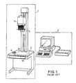
- Fig. 1 shows a typical example of the digitizer system presently available in the art and largely comprises a projection unit 1 coupled to a desktop-size computer system 2.
- the projection unit 1 comprises a screen table 3 with an image forming area 3a, a supporting pole 4 upwardly projecting from the table 3, a projector 5 movable along the supporting pole 4, and a positioner 6 for assigning a frame for an image fallen upon the image forming area.
- the image forming area 3a is associated with a magnification ratio detector 3b, and the magnification ratio detector 3b decides the magnification ratio of the image in the area 3a depending upon the distance between the screen table 3 and the projector 5.
- the editor inserts the photograph into the projector 5, and assigns a frame in the image forming area 3a with the positioner 6.
- the projector 5 is moved upwardly or downwardly so that the image on the photograph is matched with the frame previously assigned, and the image thus regulated in size is converted into digital signals which are transferred to the desktop size computer system for displaying.
- the magnification ratio detector 3b decides the magnification ratio depending upon the frame size and the distance between the projector 5 and the screen table 3, and the magnification ratio is also reported to the desktop size computer system.
- the digitizer system semi-automatically arranges the layout and automatically calculates the magnification ratio, so that the magnification ratio is free from errors made in calculation and in input of the data indicative of the sizes of the original photograph and the frame assigned thereto.
- the digitizer system is so large and expensive that the editor can not privately use it, and, for this reason, his schedule is frequently disturbed by another editor.
- the present invention proposes to calculate a ratio of a first distance to a second distance with a built-in calculator.
- an electronic rule comprising a) a rule unit including a graduated member and a slider member supported by the graduated member and movable therealong, the slider member having a mark for providing an interrelation between the graduated member and an object, b) measuring means for deciding a distance between two target points depending upon a length over which the slider member is moved, and c) magnifi cation ratio calculating means for calculating a ratio of a first distance to a second distance, the first and second distances being decided by the measuring means and supplied thereto.
- an electronic rule embodying the present invention largely comprises a rule unit 21 and electronic circuits (shown in Fig. 6) associated with the rule unit 21 and communicable with switches 22a, 22b, 22c, 22d and 22e, an encoder as well as with a liquid-crystal display panel 26.
- the rule unit 21 comprises a graduated member 21a and a slider member 21b movable along the graduated member 21a, and the graduated member 21a has a rail block connected at both ends thereof to weight blocks 21d and 21e, respectively.
- a transparent plate 21f of, for example, a synthetic resin projects from one side of the rail block 21c, and a plurality of scratched lines 21g are provided along the edge of the transparent plate 21f at regular intervals.
- Each interval between the adjacent scratched lines 21g is equivalent to a unit of length (or one millimeter), and the leftmost line is spaced from the rightmost line by 30 centimeters.
- Each of the weight blocks 21d and 21e is a generally inverted-L in cross section, so that an editor easily grasps at the weight blocks 21d and 21e, carries and put it on a block copy by way of example.
- the total weight of the electronic rule is light enough for an ordinary editor to carry in his hands, but the weight blocks 21d and 21e provide a stability to the electronic rule.
- the slider member 21b is supported on the rail block 21c, and a hollow space is formed in the slider member 21b.
- a circuit board 21h where a plurality of semiconductor integrated circuit devices 21i including a single-chip microcomputer are mounted and electrically interconnected for communication.
- Aforementioned electronic circuits are implemented by the semiconductor integrated circuit devices 21i and will be described in detail with reference to Fig. 6.
- the hollow space is closed with the liquid-crystal display panel 26, and the liquid-crystal panel 26 is driven by one of the semiconductor integrated circuits 21i under the supervision of the single chip microcomputer.
- the flexible strip 21j is formed with a narrow line 21k at the leading end portion thereof, and the cursor 21j provides an interrelation between a target point and the scratched lines 21g.
- the narrow line 21k thus formed at the leading end portion makes the editor easily decide the initial and terminal points of a line to be measured.
- Fig. 5 of the drawings the arrangement of the manipulating panel is illustrated and comprises the liquid-crystal display panel 26 occupying most of the manipulating panel and the five switches 22a to 22e labeled with 'ENTER", "%”, “ZERO”, “CNF” and “ON/OFF", respectively.
- On the liquid-crystal display panel are formed an Arabic numeral accompanied with a unit of length "mm (millimeter)", and the Arabic numeral is indicative of a distance over which the slider unit 21b travels.
- the switch “ON/OFF” 22e is of the toggle switch for power-on and power-off, and the switches 22a to 22d are respectively assigned instructions to the single chip microcomputer. Namely, the switch 22a is depressed when the cursor "ENTER” 21j reaches the terminal point of a line to be measured, and the distance thus traveled is internally memorized in response to the instruction to be given through depressing the switch 22a.
- the switch "%” 22b stands for an instruction of calculation, and a ratio between two distances is calculated in response to the instruction given through depressing the switch 22b.
- the switch 22c is provided for power saving as well as decision of an initial point of a line to be measured.
- the switch 22c is continuously depressed over, for example, a second, such a long manipulation allows fetching a positional data signal indicative of the initial point.
- the switch 22c is depressed for a while less than 1 second, the liquid-crystal display panel 26 is deenergized and, accordingly, all of the characters disappears from the display panel 26.
- the switch 22d allows the liquid-crystal display panel 26 to indicate two kinds of data one of which is estimated on the basis of the ratio between two distances calculated upon depressing the switch 22b and the other of which is actually measured by adjusting the cursor 21j. Comparing these two kinds of data, the editor confirms whether or not the actual distance is fallen within the range estimated through calculation.
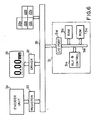
- the arrangement of the electronic circuits associated with the slider member 21b is illustrated in Fig. 6.
- the electronic circuits includes the single chip microcomputer 31, a panel driver 32 coupled to the liquid-crystal display panel 26 and a data registor 33 for memorizing a positional data signal periodically fed from an encoder unit 34 of a capacitor array type.
- the single-chip microcomputer 31 contains a combined circuit of an arithmetic-and-logic unit and a controlling unit 31a (which is simply referred to as "control" hereinbelow), a random access memory 31b for working registors, a read only memory for an instruction storage, an input-and-output port 31d and an internal bus system 31e interconnecting these component circuits; however, those component circuits are well known in the art, and, for this reason, no further description is incorporated.
- the input-and-output port 31d is coupled to an external wiring system 35 which in turn is coupled to the switches 22a to 22e, the panel driver 32 and the data registor 33, and the single chip microcomputer 31 periodically scans the switches 22a to 22e and checks to see whether or not the switches 22a to 22e are manipulated.
- the single chip microcomputer 31 is communicable with the panel driver 32 and gives instructions thereto for displaying either distance or ratio.
- the signal chip microcomputer 31 periodically accesses the data registor 33 and fetches the positional data signal which are used for determination of a distance.
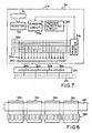
- the encoder unit 34 of the capacitor array type is well known in the art and, for this reason, briefly described with reference to Figs. 7 and 8.
- the encoder unit 34 has a plurality of emitting electrodes 34a disposed in a row, and the emitting electrodes 34a are provided in the slider member 21b.
- the encoder unit 34 further has a plurality of receiving electrodes 34b and a plurality of spacing electrodes 34c alternately disposed in a row and embedded in the rail block 21c. Since the spacing electrodes 34c is grounded, each of the receiving electrodes 34b is electrically isolated from the adjacent receiving electrodes 34b and fixed to a certain voltage level different from the ground voltage level.
- the receiving electrodes are opposed to the emitting electrodes 34a in spacing relationship, and the emitting electrodes 34a are laterally movable over the receiving electrodes 34c with the slider member 21b.
- the emitting electrodes 34a are grouped by eight, and the emitting electrodes 34a of each group are coupled to eight signal lines 34d, respectively.
- the eight signal lines 34d respectively propagate alternating currents slightly different in phase from one another, and the alternating currents are produced by a phase shifter 34e and supplied in parallel to the eight signal lines 34d.
- the emitting electrodes 34a are capacitively coupled to the receiving electrodes 34c, and the total capacitance is varied in the presence of the alternating currents depending upon the relative location between the emitting electrodes 34a and the receiving electrodes 34b.
- the capacitive signals thus transferred between the emitting electrodes 34a and the receiving electrodes 34b are monitored by an auxiliary elec trode 34f, and the auxiliary electrode 34f reports the variation to a periodic detecting circuit 34f.
- the periodic detecting circuit 34f decides the amount of movement in either direction, and the total amount of movement is memorized in a summing circuit 34g in the form of a digital code.
- the total amount of movement is indicative of a position spaced apart from a starting or "zero" point, and the positional data signal representative of the position is fed from the data registor 33 through the external wiring system 35 to the single chip microcomputer 31.
- Fig. 8 shows the relativity between the emitting, receiving and auxiliary electrodes 34a, 34b, 34c and 34f on the assumption that these electrodes 34a, 34b, 34c and 34f are projected on a virtual plane.
- the editor traces a sequence illustrated in Figs. 10A and 10B for deciding a magnification ratio between the original photograph 43 and the area 41 assigned thereto.
- the editor picks up a photograph as by step S1, and checks the photograph to see whether or not the photograph is match for an article as by step S2. If there is found that the photograph is not match for the article, the answer to the step S2 is given in the negative, and the editor returns to the step S1 for another photograph.
- the editor reiterates the loop consisting of the steps S1 and S2 and selects the photograph match for the article.
- step S2 If a photograph is match for the article, the answer to the step S2 is given in the positive, and the editor adjusts the leftmost corner 43a to the mark on a rule as by step S3.
- the editor reads and memorizes the position of the leftmost corner 43a on the rule as by step S4, and adjusts the rightmost corner 43b to the rule as by step S5.
- the position of the rightmost corner 43b is read on the rule and memorized again as by step S6. If the positions of both corners are thus decided, the value of the leftmost position is subtracted from the value of the rightmost position as by step S7, and a distance L10 between the corners 43a and 43b is determined through the subtraction. If any error is made in the measurement or in the calculation, the answer to step S8 is given in the negative, and the editor repeats the loop consisting of the steps S3 to S8 until the answer to the step S8 changes in the positive.
- step S9 to direct his attention to the block copy 42.
- the editor checks any frame in the block copy 42 to see whether or not the frame serves as the area assigned to the photograph 43 as by step S10. If the frame is not desirable for the area 41, the answer to the step S10 is given in the negative, and the editor returns to the step S9 to select the area from the frames.
- the editor reiterates the loop consisting of the steps S9 and S10 until the editor looks for the area 41 assigned to the photograph 43. If the editor finds the area 41 assigned to the photograph 43, he proceeds to step S11 to adjust the leftmost corner 41a to the mark point on the rule as by step S11.
- the editor reads the position of the leftmost corner 41a and memorizes it as by step S12.
- the editor adjusts the rightmost corner 41b to the rule again as by step S13, and the position of the rightmost corner 41b is read and memorized by the editor as by step S14.
- a distance between the leftmost corner 41a and the rightmost corner 41b is given by subtracting the value of the leftmost corner 41a from the value of the rightmost corner 41b as by step S15. If any error is made in the measurement, the answer to step S16 is given in the negative, then the editor returns to the step S11 and repeats the loop consisting of the steps S11 to S16.
- the magnification ratio R10 thus calculated is memorized in association with the photograph 43 as by step S18, and the arrangement of the photograph 43 is completed as by step S19.
- Fig. 11 shows the sequence of a main routine program executed by the single chip microcomputer 31.
- data codes memorized in the working registors 31b are briefly described hereinbelow.
- One of the working registors 31b is assigned a flag "DISPLAY". If the flag "DISPLAY” is set to be “1", the panel driver 32 allows the liquid-crystal display 26 to indicate a distance or a ratio; however, the flag "DISPLAY" of "0" instructs the panel driver 32 to deenergize the liquid-crystal display 26.
- the working registor assigned the flag is also referred to as "DISPLAY”.
- a timer is implemented by a software, and a data code labeled with "TIMER” is indicative of the lapse of time from execution of the software for the timer.
- TIMER One of the working registors 31b is assigned to the data code "TIMER”, and the working registor is also referred to as "TIMER”.
- a data code "INITIAL” is indicative of the position of an initial point on the rule, and any distance is measured from the initial point. In other words, any of the distances is given as an interval between the initial point and a target point.
- the data code "INITIAL” is memorized in another working registor labeled with "INITIAL”.
- a data code "POSITION” is memorized in still another working registor "POSITION”, and is indicative of the position of the cursor 21j.
- the single chip microcomputer 31 periodically fetches the positional data signal and produces the data code "POSITION”.
- index code is memorized in still another working registor labeled with "INDEX”, and the index code "INDEX” is indicative of the status in the program sequence. Namely, if the index code "INDEX" is "1”, the initial position has been decided and memorized in the working registor "INITIAL”, and the single chip microcomputer 31 is allowed to calculate the actual lateral distance L10 of the original photograph 43.
- the index code "INDEX" of value 2 allows the single chip microcomputer 31 to calculate the actual lateral distance L20 of the area 41 and a magnification ratio between the distances L10 and L20, but the single chip microcomputer 31 measures an actual vertical distance L30 and estimates a vertical distance L40 in the presence of the index code "INDEX" of value "3".
- the index code "INDEX” of value 4 the single chip microcomputer 31 measures an actual vertical distance L50 of the area 41, and the index code "INDEX” of value 5 allows the single chip microcomputer 31 to estimate a lateral distance L60 for comparing the actual lateral distance L10 with the distance L60 to be estimated.
- Figs. 14A and 14B Detailed description will be made with reference to Figs. 14A and 14B.
- a data code "DISTANCE 1" is assigned to still another working registor 31b and is indicative of the actual lateral distance L10 of the original photograph 43.
- a data code “DISTANCE 2” is indicative of the actual lateral distance L20 of the area 41 in the block copy 42, and one of the working registors 31b is assigned to the data code "DISTANCE 2”.
- Data codes "DISTANCE 3" and “DISTANCE 4" respectively stand for the actual vertical distance L30 of the original photograph 43 and the actual vertical distance L50 of the area 41, and the working registors assigned the distances L10, L20, L30 and L50 are named with the same labels.
- a ratio of the actual lateral distance L20 to the actual lateral distance L10 is calculated by the single chip microcomputer 31 and is memorized in a working registor "RATIO 1".
- the ratio is referred to as "RATIO 1" in the program sequence.
- the single chip microcomputer 31 further calculates a ratio of the actual vertical distance L50 to the actual vertical distance L30, and the ratio is labeled with "RATIO 2".
- the ratio "RATIO 2" is assigned to still another working registor "RATIO 2", and those ratios are used by the editor to see whether or not the actual distances "L50 and "10" are fallen within respective ranges.
- the single chip microcomputer 31 estimates the distance L40. If the distance L40 is smaller than the actual vertical distance L50, the area 41 is large enough to accommodate a shrunk or enlarged photograph. However, if not, some rearrangement may be necessary. With the ratio "RATIO 2", the single chip microcomputer 31 further estimates the lateral distance L60, and the editor confirms that the actual distance L10 is larger than the distance L60 to be estimated.
- the main program sequence starts with an initialization sub-routine program SR100 where the flag "DISPLAY”, the index code “INDEX” and the working registors “TIMER”, “INITIAL”, “POSITION”, “DISTANCE 1” to “DISTANCE 4", "ESTIMATE 1” and “ESTIMATE 2" are supplied with the flag, the index code and the data codes of value "0", respectively.
- initializing process are executed for the electronic circuits, however, no description is incorporated because such an initializing process is not directly related to the gist of the invention.
- step S101 to check the manipulating panel to see whether or not the switch "zero" 22c is manipulated or depressed by the editor. If there is found that the switch 22c is depressed, the answer to the step S101 is given in the positive, then the single chip microcomputer 31 proceeds to a sub-routine program SR200 illustrated in Fig. 12; however, if the answer to the step S101 is given in the negative, no manipulation is made on the switch 22c, then the single chip microcomputer 31 proceeds to a sub-routine program SR300 illustrated in Fig. 13.
- the single chip microcomputer 31 proceeds to the sub-routine program SR300.
- the single chip microcomputer 31 checks the working registor array to see whether or not the index code "INDEX" is equal to or larger in value than value "1" as by step S301. Since the index code "INDEX" has been set to be value "0" in the initialization program SR100, the answer to the step S301 is given in the negative, then the single chip microcomputer 31 immediately returns to the main routine program without any execution of steps S302 to S306.
- the single chip microcomputer 31 sequentially checks the switches 22a, 22b and 22d to see whether or not any one of the switches 22a, 22b and 22d is manipulated by the editor as by steps S102 to S104. If one of the switches 22a, 22b and 22d is manipulated, the answer to the step S102, S103 or S104 is given in the positive, then the single chip microcomputer 31 proceeds to a sub-routine program SR400, SR500 or SR600. However, when there is found that no switch is manipulated by the editor, the single chip microcomputer 31 returns to the step S101 and reiterates the loop consisting of the steps S101 to S104 until any one of the switches 22a to 22d is manipulated.
- any one of the switches 22a, 22b and 22d may be manipulated by the editor, and the single chip microcomputer 31 is, accordingly, branched to the associated sub-routine program SR400, SR500 or SR600, however, the single chip microcomputer 31 immedi strictlyately returns to the main routine program. Namely, if the "enter" switch 22a is manipulated prior to any manipulation of the "zero” switch 22c, the single chip microcomputer 31 checks the working registor array to see whether or not the index code "INDEX" is equal to value "0" as by step S401 (see Fig. 14B).
- the index code (which has been set to be value "0" in the initialization sub-routine program) causes the answer to the step S401 to be given in the positive, and the single chip microcomputer 31 immediately returns to the main routine program. Similarly, the index code of value "0" causes the answer to steps S501 and S601 to be given in the negative, and the single chip microcomputer 31 immediately returns to the main routine program. This results in that any distance or ratio is calculated by the single chip microcomputer 31 prior to deciding an initial position of the cursor 21j for preventing the editor from any incorrect suggestion.
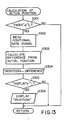
- the single chip microcomputer 31 checks the working registor array to see if the data code "TIMER” has value "0" or not as by step 201.
- the data code "TIMER” has been set to be value "0" in the initialization sub-routine program, so that the answer to the step S201 is given in the positive, and the single chip microcomputer 31 proceeds to step S202.
- the timer (which is implemented by software) starts with incrementing the data code "TIMER", and the single chip microcomputer 31 returns to the main routine program.
- the single chip microcomputer 31 is branched from the main routine program to the sub-routine program SR200 because the answer to the step S101 is given in the positive again.
- the answer to the step S201 is changed from the positive to the negative due to the execution of the step S202, so that the single chip microcomputer 31 proceeds to step S203 where the data code "TIMER” is incremented by "one".
- the single chip microcomputer 31 then checks the working registor array to see if the data code "TIMER" reaches a predetermined value N indicative of a second or not as by step S204.
- the single chip microcomputer 31 If the data code "TIMER" is less than the predetermined value N, the answer to the step S204 is given in the negative, and the single chip microcomputer 31 resets the flag "DISPLAY” to be value "0" as by step S205. With the flag "DISPLAY” of value "0”, the single chip microcomputer 31 instructs the panel driver 32 to deenergize the liquid-crystal display panel 26 as by step S206. After the execution at the step S206, the single chip microcomputer 31 returns to the main routine program. If the editor stops depressing the "zero" switch 22c within a second, the liquid-crystal display panel 26 is deenergized only, and the manipulation less than a second is useful after each regulation of the area 41 because of the power saving.
- step S204 the answer to the step S204 is given in the positive. Then, the single chip microcomputer 31 proceeds to step S207 and accesses to the data registor 33.
- the positional data signal representative of the current position of the cursor 21j is periodically supplied from the electric encoder unit 34 and memorized therein.
- the positional data signal in the data registor 33 is fetched by the single chip microcomputer 31 as by step S207, and is transferred to the working registor "INITIAL".
- step S208 the single chip microcomputer 312 proceeds to step S209 and sets the flag "DISPLAY” to be value "1". If the flag "DISPLAY” has value "1", the panel driver 32 energizes the liquid-crystal display panel 26. Then, the single chip microcomputer 31 instructs the panel driver 32 to indicate "0.00 mm” on the liquid-crystal display panel 26.
- the Arabic numeral "0.00” means that the cursor 21j is adjusted to the initial position, and the editor matches the leftmost corner 43a of the original photograph 43 with the cursor 21j.
- the single chip microcomputer 31 then proceeds to step S211 where the index code "INDEX" is incremented by one.
- the single chip microcomputer 31 resets the timer to be value "0" as by step S212 so that the timer is ready for counting the lapse of time again. After the step S212, the single chip microcomputer 31 returns to the main routine program.
- the electric encoder unit 34 measures the length over which the slider member 21b travels, and the positional data signal is successively fed to the data registor 33 so as to indicate the position of the cursor 21j.
- step S101 is repeatedly executed by the single chip microcomputer 31.
- the index code "INDEX” has been incremented at the step S211 of the subroutine program SR200, and, for this reason, the answer to the step S301 is given in the positive.
- the single chip microcomputer 31 proceeds to step S302 and fetches the positional data signal memorized in the data registor 33.
- the single chip microcomputer 31 calculates the difference between the value indicated by the data code "INITIAL” and the value of the positional data signal as by step S303. The difference is indicative of the current position of the cursor 21j and is transferred to the working registor "POSITION" as by step S304.
- the data code "POSITION” becomes to be equal in value to the difference between the initial data code and the positional data signal.
- the single chip microcomputer 31 then checks the working registor array to see whether or not the flag "DISPLAY” has value "1" as by step S305.
- the flag "DISPLAY” is set to be value "0" in so far as the editor does not depress the "zero” switch 22c over a second.
- the panel driver 32 allows the value indicated by the data code "POSITION” to be displayed on the liquid-crystal display panel 26.
- the single chip microcomputer 31 then returns to the main routine program, but is repeatedly branched to the sub-routine program SR300 while the slider member 21b slides on the transparent graduated plate 21f.
- the single chip microcomputer 31 periodically renews the position of the cursor 21j, and the position of the cursor 21j thus renewed is indicated on the liquid-crystal display panel 26.
- the editor depresses the "enter"switch 22a, and the answer to the decision step S102 is given in the positive.
- the single chip microcomputer 31 is branched to the sub-routine program SR400 illustrated in Figs. 14A and 14B.
- step S401 Since the index code "INDEX" has been incremented at the step S211 of the sub-routine program SR200, the answer to the decision step S401 is given in the negative, and the single chip microcomputer 31 proceeds to step S402 and checks the working registor array to see if the index code "INDEX" is set to be value "1". While the editor measures the distance L10, no "enter” switch 22c has been depressed yet, and, for this reason, the index code "INDEX” was incremented once as by the step S211. Then, the answer to the decision step S402 is given in the positive, and the single chip microcomputer 31 calculates the difference between the data codes "POSITION" and "INITIAL” as by step S403.
- the data code POSITION" is indicative of the current position of the cursor at the rightmost corner 43b, so that the difference means the distance L10 between the leftmost corner 43a and the rightmost corner 43b.
- the single chip microcomputer 31 transfers the difference to the working registor "DISTANCE 1" so that the data code "DISTANCE 1" is set to be the value equivalent to the distance L10.
- the single chip microcomputer 31 increments the index code "INDEX” as by step S405, and the index code "INDEX” has value "2" in this stage.
- the single chip microcomputer 31 then returns to the main routine program.
- the single chip microcomputer 31 While the editor moves the electronic rule to the block copy 42, the single chip microcomputer 31 continues to periodically fetch the positional data signal; however, no variation would takes place in so far as the editor fixes the slider member 21b.
- the editor adjusts the cursor 21j to the leftmost corner 41a of the area 41, and, then, causes the slider member 21b and, accordingly, the cursor 21j to move along the transparent graduated plate 21f.
- the cursor 21j arrives at the rightmost corner 41b of the area 41, the editor adjusts the cursor 21j to the rightmost corner 41b and depresses the "enter" switch 21a again. Then, the single chip microcomputer 31 acknowledges the manipulation through the periodical scanning, and the answer to the decision step S102 is given in the positive.
- the single chip microcomputer 31 is branched to the sub-routine program SR400, and the answers to the decision steps S401 and S402 are each given in the negative because the index code "INDEX" is incremented by one at each of the steps S211 and S405.
- the single chip microcomputer 31 then proceeds to step S406 and checks to see if the index code "INDEX" has value "2". When the distance L20 is measured, the index code "INDEX" has value "2", and, for this reason, the answer to the decision step S406 is given in the positive.
- step S407 the single chip microcomputer 31 subtracts the value indicated by the data code "INITIAL” from the value indicated by the data code "POSITION", and the difference is transferred to the working registor "DISTANCE 2" as by step S408. This results in that the data code "DISTANCE 2" is indicative of the distance L20, and the single chip microcomputer 31 proceeds to step S409 for incrementing the index code "INDEX”. Then, the single chip microcomputer 31 returns to the main routine program.
- the editor measures both of the distances L10 and L20, and instructs the electronic rule to calculate a ratio of the distance L20 to the distance L10 (L120/L10) by depressing the percentage switch 22b.
- the manipulation of the percentage switch 22b is acknowledged at the decision step S103, and the answer to the step S103 is given in the positive.
- the single chip microcomputer 31 is branched to the sub-routine program SR500 illustrated in Fig. 15.
- the index code "INDEX" is checked to see if the value thereof is equal to or greater than "3" as by step S501. If the answer to the decision step S501 is given in the negative, the actual lateral distances L10 and L20 have not been determined yet, or the manipulation is not intentional, then the single chip microcomputer 31 returns to the main routine program for preventing the editor from incorrect suggestion. However, if the answer to the decision step S501 is affirmative, the actual lateral distances have already determined, so that the single chip microcomputer 31 checks the index code "INDEX" again to see if the value thereof is greater than five as by step S502.
- the single chip microcomputer 31 checks the flag "DISPLAY” to see whether or not the value thereof is equal to one as by step S504. If the editor does not want any display, he manipulated the "zero" switch 22c within a second, and, accordingly, the flag "DISPLAY” has been set to be value "0". In this situation, the answer to the decision step S504 is given in the negative, and the single chip microcomputer 31 immediatey returns to the main routine program without any indication on the liquid-crystal display panel 26. However, the editor usually wants the liquid-crystal display panel 26 to indicate the calculation result, and, for this reason, the index code "INDEX" remains in value "1", so that the answer to the decision step S504 is affirmative.
- the single chip microcomputer 31 proceeds to step S504 and instructs the panel driver 32 to indicate the data code "RATIO 1" on the liquid-crystal display panel 26.
- the single chip microcomputer 31 then returns to the main routine program.
- the ratio of the actual lateral distance L20 to the actual lateral distance L10 is calculated and memorized in the working registor "RATIO 1" without any manual data input.
- the electronic rule according to the present invention is free from any error made in the data input manually carried out by the editor, and, accoridngly, the ratio is correct and reliable. This is one of the advantages of the present invention.
- the original photograph 43 and the area 41 are not always similar to each other, and the editor needs to confirm that a ratio of the actual vertical distance L50 to the actual vertical distance L30 is fallen within the range equal to or less than the ration indicated by the data code "RATIO 1". Then, the editor moves the cursor 21j toward the initial position and adjust the lowest corner 43c to the datum point. When the cursor 21j returns to the initial position or the datum point, the liquid-crystal display panel 26 indicates the positional data code "0.00 mm", so that the editor easily realizes the arraival at the datum point.
- the editor moves the slider member 21b and, accordingly, hte cursor 21j in the right direction. If the cursor 21j is adjusted to the corner 43b, the positional data signal is fetched by the single chip microcomputer 31, and the data code "POSITION" is indicative of the length over which the cursor 21j travels as described hereinbefore.
- the "center" switch 22a is depressed by the editor. Then, the single chip microcomputer 31 aknowledges the depressing at the decision step S102, and proceeds to the sub-routine program SR400 with the positive answer to the decision step S102.
- step S414 The answer to the decision step S414 is usually affirmative, and, for this reason, the panel driver 32 allows the liquid-crystal display panel 26 to display the vertical distance L40 as by step S415.
- the index code "INDEX" is then incremented by one as by step S416, and the single chip microcomputer 31 returns to the main routine program.
- the distance L40 is indicative of the maximum value of the vertical edge of the area 41, and the editor needs to confirm that the actual vertical distance L50 is not greater than the diatance L40.
- the editor causes the slider member 21b and, accoridngly, the cursor 21j to return to the datum point, and the cursor 21j is matched with the lowest corner 41c.
- the editor then moves the cursor 21j and adjusts it to the corner 21b.
- the position of the cursor 21j is indicated by the positional data signal, and hte positional data siganl is fetched by the single chip mcrocomputer 31 so as to produce the data code "POSITION".
- the editor depresses the "enter" switch 22a, the answer to the decision step S102 is affirmative, and, accordingly, the single chip microcomputer 31 is branched to the sub-routine program SR400.
- the index code "INDEX” allows the single chip microcomputer 31 to proceeds to step S417, and the single chip microcomputer 31 further proceeds to step S418 because the answer to the decision step S417 is affirmative.
- the single chip mcirocomputer 31 subtracts teh value of the data code "INITIAL” from the value indicated by teh data code "POSITION”, adn the difference is transferred to the working registor "DISTANCE 4" as by step S419.
- the data code "DISTANCE 4" thus produced is indicative of the length over which the cursor 21j travels, and hte index code "INDEX" is incremented by one as by step SS420.
- the single chip microcomputer 31 then returns to the main routine program.
- the panel driver 32 was instructed that the vertical distance L40 was displayed at the step S415, so that the vertical distance is still displayed on the liquid-crystal display panel 26 at this stage.
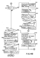
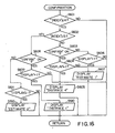
- the answer to hte decision step S104 turns affirmative, and, accoridngly, the single chip microcomputer 31 is branched to the sub-routine program SR600 illustrated in Fig. 16.
- the single chip microconputer 31 thus branched checks the working registor array to se if the value of the index code "INDEX" is equal to or greater than four as by step S601.
- step S601 If the manipulation is carried out prior to the measurement of the actual vertical distance L50, the answer to the desicion step S601 is given in the negative, so that the single chip microcomputer 31 immediately returns to the main routine program. However, if the answer to teh decision step S601 is affirmative, both of the vertical distances L40 and L50 have been already determined and memorized in the working registor array, then the single chip microcomputer 31 proceeds to step S602 to see if the index code "INDEX" is greater than five. If the actual vertical distance L50 has been just measured, the index code "INDEX" is incremented by one at the step S420, and the answer to teh decision step S602 is given in the negative.
- the single chip microcomputer 31 proceeds to step S603 to see whether or not the confirmation switch 22d is still depressed. If the editor continues to depress the confirmation switch 22d, the single chip microcomputer 31 checks the flag "DISPLAY” to see if the value thereof is equal to one as by step S604. If the value of the flag "DISPLAY” is zero, the editor wants any indication to disappear from the liquid-crystal display panel 26, so that the single chip microcomputer 31 immediately returns to the main routine program. However, since the flag "DISPLAY" is usually set to be vaue "1", the single chip microcomputer 31 instructs the panel driver 32 to display the actual vertical distance L50 indicated by teh data code "DISTANCE 4" as by step S605. Then, the single chip microcomputer 31 returns to the main routine program, and the liqueid-crystal display panel 26 continues to display the actual vertical distance L50.
- the single chip microcomputer 31 checks the working registor array to see if the flag "DISPLAY” is equal to one as by step S606.
- the flag "DISPLAY” is usually set to be value "1", and, for this reason, the single chip microcomputer 31 instructs the panel driver 32 to indicate the vertical distance L40 indicated by the data code "ESTIMATE 1" as by step S607.
- the single chip microcomputer 31 then returns to the main routine programs and the liquid-crystal display panel 26 continues to display the vertical distance L40 to be estimated.
- the single chip microcomputer 31 alternates the vertical distance L40 with the actual vertical distance L50 depending upon the confirmation switch 22d, so that the editor easily confirms that the vertical distance L40 to be estimated is fallen within the range to be allowed. If the flag "DISPLAY" is usually set to be value "1", and, for this reason, the single chip microcomputer 31 instructs the panel driver 32 to indicate the vertical distance L40 indicated by the data code "ESTIMATE 1" as
- the editor needs to determine a new magnification ratio, so that the editor depresses the percentage switch 22b.
- the answer to the decision step S103 is affirmative, and the single chip microcomputer 31 is branched to the sub-routine program SR500.
- the value of the index code "INDEX" is equal to five in this stage, and the answer to the decision step S501 is affirmative, but the answer to the decision step S502 is given in the negative.
- the ratio thus calculated is memorized in the working registor "RATIO 2", and the index code "INDEX" is checked to see if the value thereof is equal to one as by step S507. If the answer to the decision step S507 is given in the negative, the single chip microcomputer 31 immediately returns to the main routine program, but the answer to the decision step S507 is usually affirmative, then the single chip microcomputer 31 instructs the panel driver 32 to display the ratio indicated by the data code "RATIO 2". The single chip microcomputer 31 then returns to the main routine program.
- the editor confirms that the new ratio is correct in terms of the actual lateral distance L10.
- the editor measures the actual lateral distance L20, and depresses the "enter" switch 22a.
- the "enter” switch 22a thus depressed is acknowledged at the decision step S102, and the single chip microcomputer 31 is branched to the sub-routine program SR400.
- the single chip microcomputer 31 then checks the working registor array to see if the flag "DISPLAY” has value "1" as by step S423. If the answer to the decision step S423 is given in the negative, the single chip microcomputer 31 immediately returns to the main routine program. However, since the flag "DISPLAY” is usually set to be value "1", the single chip microcomputer 31 instructs the panel driver 32 to display the lateral distance L60 indicated by the data code "ESTIMATE 2". The single chip microcomputer 31 then proceeds to step S425 and increments the index code "INDEX”, then retuning to the main routine program for recycling the loop.
- the editor depresses the confirmation switch 22d, and the single chip microcomputer 31 is branched from the step S104 to the sub-routine program SR600. Since the index code "INDEX" was incremented at the step S425, the answer to the decision step S601 is given in the negative, but the single chip microcomputer 31 proceeds to step S608 with the positive answer to the decision step S602. At the step S608, the single chip microcomputer 31 checks the confirmation switch 22d to see whether or not the switch 22d is still depressed by the editor.
- step S608 If the editor continues to depress the confirmation switch 22d, the answer to the decision step S608 is affirmative, so that the flag "DISPLAY” is checked to find if the value thereof is equal to one as by step S609. Whenever the flag "DISPLAY” is reset to be value "0", the single chip microcomputer 31 immediately returns to the main routine program. However, the flag "INDEX” is usually set to be value "1", so that the single chip microcomputer 31 instructs the panel driver 32 to cause the liquid-crystal display panel to display the actual lateral distance L10. The single chip microcomputer then returns to the main routine program.
- step S608 the confirmation switch 22d is released and, accordingly, the answer to the decision step S608 is given in the negative. Then, the flag "DISPLAY" is checked again as by step S611, and the single chip microcomputer usually proceeds to step S612 with the positive answer to the decision step S611 for giving an instruction so as to display the lateral distance L60 indicated by the data code "ESTIMATE 2". Then, the liquid-crystal display panel 26 indicates the lateral distance L60 even though the single chip microcomputer 31 returns to the main routine program.
- the single chip microcomputer 31 alternates the lateral distances L60 with the actual lateral distance L10 depending upon the manipulation of the confirmation switch 22d, and the editor can confirm that the lateral distance L60 to be estimated is smaller in value than the actual lateral distance L10.
- the casting off is completed for the original photograph 43, and the editor depresses the "zero" switch 22c for a while less than a second, thereby saving the power consumption.
- the "zero" switch 22c is depressed over a second, and not only the main routine program but also the sub-routine programs SR200 to SR600 are repeated by the single chip microcomputer 31.
- the electronic rule according to the present invention is free from any error made in the data input because the single chip microcomputer 31 memorizes the distances L10, L20, L30 and L50 in the working registor array and further fetches those data upon calculating the ratios.
- the electronic rule according to the present invention is further advantageous over the prior art digitizer system in cost and manipulability because the built-in calculator associated with the encoder unit 34 carries out the calculation. This results in that each editor privately uses the electronic rule, and, for this reason, the casting off is quickly completed with the assistance of the electronic rule.
- datum point may be established upon each measurement, and the "zero" switch 22c is manipulated upon each establishment of the datum point.
Landscapes
- Physics & Mathematics (AREA)
- General Physics & Mathematics (AREA)
- Length Measuring Devices With Unspecified Measuring Means (AREA)
- Calculators And Similar Devices (AREA)
- Measurement Of Length, Angles, Or The Like Using Electric Or Magnetic Means (AREA)
Applications Claiming Priority (2)
| Application Number | Priority Date | Filing Date | Title |
|---|---|---|---|
| JP48271/89U | 1989-04-26 | ||
| JP4827189U JPH02140404U (fr) | 1989-04-26 | 1989-04-26 |
Publications (2)
| Publication Number | Publication Date |
|---|---|
| EP0394880A2 true EP0394880A2 (fr) | 1990-10-31 |
| EP0394880A3 EP0394880A3 (fr) | 1991-11-21 |
Family
ID=12798780
Family Applications (1)
| Application Number | Title | Priority Date | Filing Date |
|---|---|---|---|
| EP19900107575 Withdrawn EP0394880A3 (fr) | 1989-04-26 | 1990-04-20 | Règle électronique à grandeur de main avec calculateur incorporé |
Country Status (2)
| Country | Link |
|---|---|
| EP (1) | EP0394880A3 (fr) |
| JP (1) | JPH02140404U (fr) |
Cited By (3)
| Publication number | Priority date | Publication date | Assignee | Title |
|---|---|---|---|---|
| GB2349473A (en) * | 1999-03-04 | 2000-11-01 | Bert Corp Ltd | Electronic caliper and apparatus for calculating body fat percentage and/or body density |
| DE102005039876A1 (de) * | 2005-08-23 | 2007-03-15 | OCé PRINTING SYSTEMS GMBH | Anordnung und Verfahren zum Erfassen der Lage einer Positionsmarke eines Trägermaterials relativ zu einem Drucker oder Kopierer |
| DE102007033519A1 (de) * | 2007-07-18 | 2009-01-22 | Shay Safranek | Elektronisches Lineal |
Family Cites Families (8)
| Publication number | Priority date | Publication date | Assignee | Title |
|---|---|---|---|---|
| JPS5492318A (en) * | 1977-12-29 | 1979-07-21 | Ricoh Co Ltd | Variable power determining device |
| US4257107A (en) * | 1978-05-22 | 1981-03-17 | Heymsfield Steven B | Measuring device |
| JPS57179601A (en) * | 1981-04-29 | 1982-11-05 | Akio Seki | Desk top calculator with electronic scale |
| GB2137002B (en) * | 1983-02-23 | 1986-11-19 | Casio Computer Co Ltd | Electronic scale |
| JPS59177531A (ja) * | 1983-03-29 | 1984-10-08 | Fuji Xerox Co Ltd | 原稿載置台の原稿位置合せ部材に設けたスライド式倍率設定機構 |
| FR2555779B1 (fr) * | 1983-11-30 | 1986-10-24 | Delecluse Brigitte | Dispositif pour obtenir par affichage la lecture directe d'une dimension sur un plan quelle que soit son echelle |
| JPS60184809A (ja) * | 1984-12-27 | 1985-09-20 | 株式会社 名南製作所 | ベニヤレ−ス |
| JPS6283770A (ja) * | 1985-10-08 | 1987-04-17 | Mita Ind Co Ltd | 画像形成装置における自動倍率設定装置 |
-
1989
- 1989-04-26 JP JP4827189U patent/JPH02140404U/ja active Pending
-
1990
- 1990-04-20 EP EP19900107575 patent/EP0394880A3/fr not_active Withdrawn
Cited By (4)
| Publication number | Priority date | Publication date | Assignee | Title |
|---|---|---|---|---|
| GB2349473A (en) * | 1999-03-04 | 2000-11-01 | Bert Corp Ltd | Electronic caliper and apparatus for calculating body fat percentage and/or body density |
| GB2349473B (en) * | 1999-03-04 | 2003-05-28 | Bert Corp Ltd | Electronic caliper and apparatus for calculating body fat percentage and/or body density |
| DE102005039876A1 (de) * | 2005-08-23 | 2007-03-15 | OCé PRINTING SYSTEMS GMBH | Anordnung und Verfahren zum Erfassen der Lage einer Positionsmarke eines Trägermaterials relativ zu einem Drucker oder Kopierer |
| DE102007033519A1 (de) * | 2007-07-18 | 2009-01-22 | Shay Safranek | Elektronisches Lineal |
Also Published As
| Publication number | Publication date |
|---|---|
| JPH02140404U (fr) | 1990-11-26 |
| EP0394880A3 (fr) | 1991-11-21 |
Similar Documents
| Publication | Publication Date | Title |
|---|---|---|
| US7256772B2 (en) | Auto-aligning touch system and method | |
| EP0394880A2 (fr) | Règle électronique à grandeur de main avec calculateur incorporé | |
| US5131079A (en) | Method of controlling a display and a display control device for a copying machine | |
| EP3125517B1 (fr) | Dispositif d'affichage et dispositif de traitement d'image | |
| US12400044B2 (en) | Dimension creation device, dimension creation method, and recording medium | |
| JPH10105322A (ja) | タブレット装置及びこれを用いた文書処理装置並びにタブレット装置制御プログラムを記憶した媒体 | |
| CN105489071B (zh) | 一种电子直尺系统及其工作方法和组成部件 | |
| JPH08292839A (ja) | 指示入力方式 | |
| JPH0428093Y2 (fr) | ||
| JPS62214771A (ja) | スキヤナ用原稿貼付シ−トの作成装置 | |
| JPH03269570A (ja) | 表示装置 | |
| CN114089842A (zh) | 电磁笔的倾斜方向的判断方法、电磁笔的游标位置计算方法及显示装置 | |
| KR20250132361A (ko) | 노광장치 및 그 제어방법, 정보 처리장치 및 정보 처리방법, 프로그램, 및 물품 제조방법 | |
| JPS644110Y2 (fr) | ||
| JP2001255998A (ja) | 位置検出システム | |
| JPH0573309B2 (fr) | ||
| JP2820424B2 (ja) | 画像パラメータ処理装置 | |
| JPS63190472A (ja) | 領域指定装置 | |
| JP2526043Y2 (ja) | 画像データ記憶装置 | |
| JPH046301Y2 (fr) | ||
| JPS61165771A (ja) | 原稿のトリミング・マスキング装置 | |
| JPH01177046A (ja) | データ入力装置 | |
| JPH0232346A (ja) | スキャナ用原稿貼付シートの作成装置 | |
| JPS62163069A (ja) | 画像形成装置 | |
| JPH0562980B2 (fr) |
Legal Events
| Date | Code | Title | Description |
|---|---|---|---|
| PUAI | Public reference made under article 153(3) epc to a published international application that has entered the european phase |
Free format text: ORIGINAL CODE: 0009012 |
|
| AK | Designated contracting states |
Kind code of ref document: A2 Designated state(s): DE GB |
|
| 17P | Request for examination filed |
Effective date: 19901228 |
|
| PUAL | Search report despatched |
Free format text: ORIGINAL CODE: 0009013 |
|
| AK | Designated contracting states |
Kind code of ref document: A3 Designated state(s): DE GB |
|
| STAA | Information on the status of an ep patent application or granted ep patent |
Free format text: STATUS: THE APPLICATION HAS BEEN WITHDRAWN |
|
| 18W | Application withdrawn |
Withdrawal date: 19920309 |
|
| R18W | Application withdrawn (corrected) |
Effective date: 19920309 |