EP0395384A2 - System und Verfahren zum Modifizieren des Ausgangs eines Analysegeräts - Google Patents
System und Verfahren zum Modifizieren des Ausgangs eines Analysegeräts Download PDFInfo
- Publication number
- EP0395384A2 EP0395384A2 EP90304461A EP90304461A EP0395384A2 EP 0395384 A2 EP0395384 A2 EP 0395384A2 EP 90304461 A EP90304461 A EP 90304461A EP 90304461 A EP90304461 A EP 90304461A EP 0395384 A2 EP0395384 A2 EP 0395384A2
- Authority
- EP
- European Patent Office
- Prior art keywords
- cartridge
- customizing
- instrument
- analytical
- signal
- Prior art date
- Legal status (The legal status is an assumption and is not a legal conclusion. Google has not performed a legal analysis and makes no representation as to the accuracy of the status listed.)
- Withdrawn
Links
Images

Classifications
-
- G—PHYSICS
- G01—MEASURING; TESTING
- G01N—INVESTIGATING OR ANALYSING MATERIALS BY DETERMINING THEIR CHEMICAL OR PHYSICAL PROPERTIES
- G01N35/00—Automatic analysis not limited to methods or materials provided for in any single one of groups G01N1/00 - G01N33/00; Handling materials therefor
- G01N35/00584—Control arrangements for automatic analysers
- G01N35/00594—Quality control, including calibration or testing of components of the analyser
-
- G—PHYSICS
- G01—MEASURING; TESTING
- G01N—INVESTIGATING OR ANALYSING MATERIALS BY DETERMINING THEIR CHEMICAL OR PHYSICAL PROPERTIES
- G01N35/00—Automatic analysis not limited to methods or materials provided for in any single one of groups G01N1/00 - G01N33/00; Handling materials therefor
- G01N35/00584—Control arrangements for automatic analysers
- G01N35/00722—Communications; Identification
- G01N35/00732—Identification of carriers, materials or components in automatic analysers
- G01N2035/00742—Type of codes
- G01N2035/00752—Type of codes bar codes
-
- G—PHYSICS
- G01—MEASURING; TESTING
- G01N—INVESTIGATING OR ANALYSING MATERIALS BY DETERMINING THEIR CHEMICAL OR PHYSICAL PROPERTIES
- G01N35/00—Automatic analysis not limited to methods or materials provided for in any single one of groups G01N1/00 - G01N33/00; Handling materials therefor
- G01N35/00584—Control arrangements for automatic analysers
- G01N35/00722—Communications; Identification
- G01N35/00732—Identification of carriers, materials or components in automatic analysers
- G01N2035/00742—Type of codes
- G01N2035/00762—Type of codes magnetic code
-
- G—PHYSICS
- G01—MEASURING; TESTING
- G01N—INVESTIGATING OR ANALYSING MATERIALS BY DETERMINING THEIR CHEMICAL OR PHYSICAL PROPERTIES
- G01N35/00—Automatic analysis not limited to methods or materials provided for in any single one of groups G01N1/00 - G01N33/00; Handling materials therefor
- G01N35/00584—Control arrangements for automatic analysers
- G01N35/00722—Communications; Identification
- G01N2035/00891—Displaying information to the operator
Definitions
- This invention relates to analytical instruments into which devices, such as cuvettes and test strips, are inserted for reading.
- test results which can be obtained objectively, quickly, preferably while the patient is still present, and in a convenient, failsafe form so that skill is not a requirement for running a test and obtaining the test results.
- level of drug administered to people with chronic illnesses such as diabetics, asthmatics, epileptics, and cardiac patients, as it appears in a physiological fluid, such as blood.
- Tests of interest include prothrombin time, potassium ion, and cholesterol. Determining red-blood-cell count is also a common test. In the case of diabetic patients, it is necessary to determine sugar level in urine or blood.
- U.S. Patent No. 4,756,884 issued to Hillman et. al . and assigned to Biotrack Corporation, the assignee of this application, teaches various embodiments of fabricating devices including a defined chamber or channel, the resulting devices, and techniques for use of such device in analyzing a fluid such as blood for the pressure of a number of different analytes.
- analyte is meant either a chemical component of the sample or a physical or chemical (biochemical) property of the sample that is being detected or measured.
- chemical analytes include electrolytes such as sodium and potassium; drugs, such as dilantin and heparin; and biochemical components, such as cholesterol and enzymes.
- properties that can be analyzed include blood clotting and sample viscosity.
- a device within the scope of this patent suitable for use in measuring prothrombin time (PT) has been commercially produced under the name Protime.
- the monitor into which the Protime cartridge is inserted for analysis utilizes a light source, such as a laser, for providing light to the blood sample and reads transmitted light in order to determine when blood flow has ceased, i.e, when the endpoint of the prothrombin reaction has been reached and blood ceases to flow through the capillary due to clot formation.
- the Protime monitor uses a fixed threshold voltage for comparing a voltage related to the the optical signal, in order to detect the endpoint of the prothrombin assay.
- the commercial prothrombin time cartridge has now been modified for use in an APTT assay. This new cartridge is described in co-pending application Serial No. 90304300.8, filed April 20, 1990.
- Instrument customization can be performed by the manufacturer; however, this requires that the manufacturer maintain several instruments in inventory that are identical except for the customization. This is costly and inefficient for the manufacturer. This approach also precludes the user from later customization, should that be desirable.
- Switches on the instrument Another method of customization that has been employed in the prior art uses mechanical switches on the instrument. If these switches are set by a service technician, a service call is required for customization. If these switches are set by the customer, it requires that the customer understand the purpose and interactions of the various switches. A non-technical customer may find the setting of switches difficult or even impossible to perform. A lack of user understanding can lead to errors in the settings and, consequently, erroneous output.
- An alternative method of customization is through an interactive menu where the user or a factory technician goes through a setup menu making selections among various options. Although typically easier than setting switches, this approach is still imperfect. It requires a technician visit with customer interaction for the setup, or else the customer is required to perform other complex selections without a full understanding of the ramifications. If the customer makes mistakes in this setup, unpredictable results may occur.
- the menu setup approach also has the disadvantage that if power is lost the setup can be lost and will have to be repeated.
- U.S. Patent 4,756,884 discloses the use of an electronic control device that is inserted into the device to confirm the correct performance of the system. Such electronic controls are usually run frequently. Often, the electronic control device also contains a code, either mechanical, optical (such as a bar code), or magnetic which, for example, indicates certain calibration or instrument set up information.
- An instrument which reads this code from the electronic control device is also capable of reading a code from the device containing analyte being read by the instrument, indicating lot-to-lot variations of cartridges, including variations in optical characteristics and/or variations in reagents contained within the cartridge and to identify the test type.
- the present invention provides a monitor customizing system, comprising an analytical instrument that provides a message to a user of the instrument, detector means in the instrument for detecting the presence of an analyte present in or property of a sample, an analytical cartridge comprising means for retaining a sample for analysis, registration means in the analytical instrument for holding the analytical cartridge in registration with the detector means, and a plurality of customizing cartridges, each of the customizing cartridges being of a predetermined class and comprising a cartridge capable of being held in the instrument by the registration means, wherein each class of customizing cartridge is encoded with a different signal and the analytical instrument comprises means for detecting the signal and means for customizing the instrument in response to the signal, wherein the means for customizing causes the instrument to provide the message in one of a plurality of predetermined formats in response to the signal provided by the class of customizing cartridge.
- the invention also provides a number of individual components for use in the system, including individual customizing cartridges and kits, and a method by which the invention is practiced. A number of advantages are provided by the preferred embodiment of using a signal detector in the location where the analytical cartridge is inserted, as will be apparant from the following detailed description given with reference to the accompanying drawings, in which:
- the present invention provides a monitor customizing system which allows an analytical instrument to provide a message to a user of the instrument in a number of different formats. For example, a number of instruments are currently provided with liquid crystal displays that provide visual prompt and error messages to users.
- the present invention allows the language in which the messages are presented to be selected by the user merely by temporarily inserting a customizing cartridge, described further below, into the analytical instrument, normally into the location on the analytical instrument that is normally used to detect the presence of an analyte in or a property of a sample being analyzed.
- a customizing cartridge described further below
- the present invention can be practiced in any analytical instrument including those currently available with only slight modification.
- the principal requirements of the instrument are that the instrument accept a sample holder, here referred to as an analytical cartridge, and that the instrument be modified to detect a signal provided by the analytical cartridge or by a different cartridge, all of which are collectively referred to as customizing cartridges, which is insertable into the same location as the analytical cartridge (or in less preferred embodiments a different location) and which contains a signal that is used to customize the instrument output.
- customizing cartridges which is insertable into the same location as the analytical cartridge (or in less preferred embodiments a different location) and which contains a signal that is used to customize the instrument output.
- the customizing system of the present invention does not rely on a particular type of analytical instrument, analytical cartridge, or analysis. Accordingly, these aspects of the system can vary widely and include all known systems or systems that are later developed in which an analytical cartridge is inserted into an instrument for the purpose of carrying out an analytical measurement on a sample retained on or in the analytical cartridge.
- the analytical cartridge can be a reagent strip comprising a handle and a porous matrix containing reagents. When a sample is applied to the matrix, a reaction occurs indicating the presence (or absence) of an analyte.
- a strip can be inserted into a reflectance spectrophotometer for determining the amount of analyte as indicated by a color reaction taking place in the matrix.
- a transmission spectrophotometer can be used if the matrix is transparent or translucent.
- the location in which the analytical cartridge is inserted is designed to specifically hold the cartridge in registration with a detector, light source, or other part of the instrument involved in detecting the presence of the analyte.
- Other types of analytical cartridges include devices with internal chambers (generally referred to as cuvettes) in which spectrophotometric measurements are made, as well as the devices described in the various patents and patent applications referenced above.
- other types of analytical instruments include nuclear magnetic resonators, radiation counters, densitometers, and instruments capable of thermal measurements.
- a key aspect of the present invention is the provision of a plurality of customizing cartridges, each of which is capable of being held temporarily in the analytical instrument, preferably by the same technique and part of the device used to hold the analytical cartridge.
- Each customizing cartridge belongs to a predetermined class, and each member of the class is encoded with the same signal, different signals being provided for different classes of customizing cartridge.
- a signal can comprise any property of matter or energy that is detectable by the instrument into which the customizing cartridge is inserted.
- Examples include bar codes (with corresponding bar-code readers in the instrument), other optical signal techniques, such as transparent and opaque (or reflective and non-reflective) locations on the customizing cartridge with corresponding light sources and detectors in the instrument, magnetic strips with magnetic readers in the instrument, differences in shape, such as provision of depressions or raised portions on a surface of the cartridge with corresponding switches or other means of detecting shape differences located in the instrument, and the like.
- Such signal and detecting means are well known, although they have not previously been used to achieve the current purpose.
- the analytical instrument also comprises some technique for customizing the instrument in response to the signal.
- customizing causes the instrument to provide a message to the user of the instrument in one of a plurality of formats in response to the signal provided by the class of customizing cartridge that is inserted into the instrument.
- a customizing cartridge can be used that causes the instrument to display messages in English or in French or in some other language. Prompts of this type are often used in medical instruments, for example to tell the user to add a sample to the reagent cartridge or perform some other action.
- the message can also be the result of the analytical measurement or can be an error or other type of data message. Additionally, measurement units in which the results are displayed can be changed under the control of the customizing cartridge.
- the message to the user can be provided in any detectable form, such as a visual display (typically using liquid crystal displays) or an audible message or code. Any other means of giving information to the user can also be provided in place of a visual or audible message.
- the customizing cartridge can be the actual analytical cartridge normally used in the device but provided with a signal.
- a paper strip containing a bar code or a magnetic strip can be affixed to a normal analytical cartridge and used to provide the signal to the instrument.
- a customizing cartridge can be provided that performs no function in the instrument other than the actual act of customizing the instrument.
- the cartridge in this case could be a dummy cartridge shaped to fit the same receptacle in the instrument as the analytical cartridge.
- a number of individual analytical and control cartridges that can be used as customizing cartridges of the present invention when provided with a signal are described below.
- the components of the present system can be provided individually by different manufacturers.
- an analytical instrument capable of carrying out an analytical reading on a sample and of detecting the signal can be prepared by one manufacturer while a second manufacturer prepares individual customizing cartridges.
- the customizing cartridges can be provided individually, or they can be provided in kits comprising more than one customizing cartridge.
- instruments shipped to Switzerland could be provided with a Swiss kit containing customizing cartridges that would provided user messages in French, German, and Italian, the three official languages of Switzerland.
- customizing kits containing English and Spanish customizing cartridges could be provided for sale in areas with large Hispanic populations.
- the method of customizing the instrument when practiced with the system as described above, is very simple and straight forward.
- the user of the instrument merely inserts a customizing cartridge into the appropriate location on the instrument, usually the same location on the instrument into which an analytical cartridge would normally be inserted.
- the signal provided by the customizing cartridge automatically customizes the instrument, as discussed above. If the customizing cartridge is a signal-encoded analytical cartridge, the instrument is customized every time an analytical cartridge is inserted into the instrument.
- Such a system is highly desirable in that it always provides language prompts and messages in the language of the user.
- the disposable cartridges can be provided in packets written in the langauge of the user so that the user automatically selects an analytical cartridge (and therefore a customizing cartridge) that provides the desired messages in the correct language. Such a situation is particularly useful in a multi-language environment where the instrument is being used by different individuals with different language skills.
- the primary intent is to provide a customizing cartridge that in insertable into the same location on the instrument as that used for the analytical cartridge
- a customizing cartridge that is temporarily inserted into a different location of the instrument.
- temporarily is meant for no more than the time between two analyses, when the customizing cartridge is not an analytical cartridge.
- the customizing cartridge is an analytical cartridge, the cartridge is retained in the instrument for the time required to carry out an analysis.
- the customizing cartridge in the embodiment of a separate customizing cartridge location to hold the cartridge in registration with the signal detecting means, is not normally present in the instrument when an analysis is being carried out.
- a magnetic strip of the type commonly found on credit cards can be used to customize an instrument by quickly passing a card on which the strip has been placed through a magnetic strip reader. This operation would be carried out between analyses.
- Other types of signal such as those exemplified above, can also be used.
- an insertable customizing cartridge which can be the analytical cartridge itself, the quality check device, or an entirely separate cartridge prepared solely for this purpose, is used to automatically customize the instrument.
- This approach has several advantages. The manufacturer has only to stock various customization cartridges, which are typically much less expensive than the instrument. A technician visit is not required in order to set the options. The setup is transparent to the user; the customer does not have to read any complicated instructions nor sort through a set of menus. Even if the batteries fail the setup is re-established when the customer re-inserts the customization cartridge. If the customization cartridge is the quality check device, customization will be re-established each time the customer runs the check device, which, regardless of its use in customization, must be run often as a quality control measure.
- one embodiment of the monitor includes 16 detectors for reading 16 bits of optical data on any type of insertable cartridge, using a single light source and, for example, a prism or light pipe for coupling light from the source to the cartridge.
- this optical code is used on the electronic control device to set the customization features.
- the customer requires prompts in two different languages, as in Canada where French and English are both official languages, he has only to order two different electronic control devices in order to customize his instrument as needed.
- the code on the analytical cartridges themselves are used both to customize the instrument during a particular sample analysis as well as to indicate lot-to-lot variations among the cartridges.
- the measurement of light e.g. scatter
- Unclotted blood, while flowing, provides an electrical signal which appears to be broadband noise, while with decreased flow rate, as blood begins to clot, the spectrum of this noise collapses to lower and lower frequencies.
- a high-pass filter with cutoff at approximately 100 Hz is used to detect when the spectrum has sufficiently collapsed to indicate prothrombin endpoint.
- Activated partial thromboplastin time is determined utilizing a cartridge having a longer capillary length (in one embodiment approximately three times as long) than the path length used in a cartride for determining prothrombin time.
- capillary path length in the APTT cartridge is within the range of approximately 18 to 31 centimeters. It has been empirically determined by the inventors that utilizing a bandpass filter centered at approximately 45 Hz provides the best analysis of the scattered light for detecting the endpoint of the APTT assay. In one embodiment, this 45 Hz bandpass filter has a 3 dB bandwidth of approximately 35 Hz.
- the 100 Hz highpass filter and the 45 Hz bandpass filter can be achieved using either hardware elements, or software control, or a combination of both.
- a fixed threshold voltage was used for comparison with the output signal from the high-pass filter used in the prothrombin time assay or the bandpass filter used for the APTT assay. It is also possible to use a floating threshold voltage (typically approximately 0.5 volts very shortly after the assay is begun, although this value will vary by perhaps a factor of 2 or 3, depending on the signal level from the sample) is utilized in order to detect not merely the crossing of a fixed threshold voltage, but rather a pronounced and sustained crossing of a variable threshold voltage.
- the signal includes an undesired dip C or variation J caused by a temporary obstruction, for example, caused by partial clotting, which temporarily decreases capillary flow, following which capillary flow is increased.
- a temporary obstruction for example, caused by partial clotting
- V t Utilizing a fixed threshold voltage V t causes an erroneous reading due to undesired dip C or variation J.
- a variable threshold voltage (curve D) which starts off at threshold voltage V t , and is subsequently reduced in order to track the gradual decrease in signal level (curve G).
- the signal at the start of an assay is relatively low, but quickly builds up to a maximum value, and then tapers off over time, as shown in the plot of Figure 1.
- false triggering is avoided by waiting a predetermined period of time before comparing the signal with the threshold voltage.
- the floating threshold voltage is initialized to a rather low value, thereby assuring that the endpoint will not be falsely triggered at the beginning of the assay, due to the relatively low signal level.
- the threshold voltage is then made to track the input signal level, and thus rises rather quickly at the beginning of the assay, as shown in Fig. 1. Since floating threshold voltage curve D remains below signal curve G by a sufficient amount, undesired variation J, which dips below a fixed threshold V t at point K, does not trigger an endpoint indication. However, since the true endpoint, which occurs at knee I, causes a very significant decrease in signal curve G, the true endpoint is indicated at point F, where signal curve G falls below floating threshold voltage curve D.
- False indications of endpoint due to dip C are avoided by testing to determine whether the signal curve G has fallen below floating threshold voltage curve D for a minimum period of time, in one embodiment 10 seconds.
- the floating threshold voltage can also be controlled in a similar manner utilizing hardware elements.
- endpoint detection is determined when capillary flow of blood being tested ceases, presumably due to clotting, as desired.
- a proper endpoint i.e that fluid flow has ceased due to clotting
- another optical source is utilized to provide light to the sample well, and a corresponding detector is used to measure the amount of light scattered from the sample well.
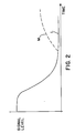
- Figure 2 is a graph depicting the signal level from the sample well detector with respect to time, indicating a decrease in the amount of blood in the sample well.
- Curve L shows the ideal curve wherein the signal level decreases to a point near zero indicating that the sample well is empty, i.e that insufficient blood was present to allow capillary flow until capillary flow ceased due to clotting.
- the assay was run until capillary flow ceased, and then a determination was made as to whether there was sufficient blood remaining in the sample well to indicate that flow ceased due to clotting, rather than due to lack of sample. No problems caused by sample drying were encountered, since the assay is complete in about 10 to 60 seconds.
- Curve M shows the undesired signal curve resulting from dried blood, i.e. over time it dries and provides increased signal which can be confused with blood remaining in the sample well.
- the signal curve L can be monitored periodically rather than simply interrogated when capillary flow ceases, in order to detect if the sample well fails to contain sufficient blood to complete the assay.
- the presence of blood in the sample well is periodically detected by monitoring curve L at intervals of approximately 2 seconds. If, at any one of these interrogations of the sample well, it is determined that the sample well has run out of blood, the test is aborted. If desired, the user then performs a new test, performed hopefully with sufficient blood to reach a true endpoint due to clotting, rather than a lack of blood in the sample well.
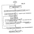
- Figure 3 is a flow chart depicting the operation of one embodiment which is further described in the software code of Appendix 1 of copending U.S. patent application Serial No. filed on April 20, 1989, on an invention of Lingane et al . entitled “Capillary Flow Device and Reading Instrument” and bearing attorney docket number BIOT-23. Notes pertaining to the flowchart of Figure 3 are as follows:
- modulated light was utilized in order to distinguish light emitted from the sample well (which lies outside of the instrument) from ambient light, which, of course, is uncontrollable in intensity and amplitude during the assay.
- an oscillator circuit is utilized to modulate the emitted light such that detected light including this modulation can be electronically separated from ambient light.
- the need for such an oscillator is obviated and emitted light is not modulated, but rather pulsed, for example, with a pulse width of approximately 400 microseconds and a pulse repetition rate of approximately 1 pulse every 2 seconds.
- the pulse Since the pulse includes relatively fast rise and fall times (typically 7 ⁇ sec) the pulse is rich in frequencies other than those contained in ambient light which typically includes frequencies of either 50 or 60 Hz and harmonics.
- the receiving circuitry is tuned to detect received light of approximately 8 kilohertz, as described in the aforementioned U.S. Patent No. 4,756,884 even though the emitted light is not modulated at 8 kilohertz, but rather consists of a series of pulses.
- light which is amplitude, frequency, or phase modulated is used.
- a test is made to determine if excessive ambient light is present, which might cause an error in reading the optical code. This is accomplished by measuring light with the emitter turned off, and determining the level of ambient light. If the level of ambient light is excessive, an error message is displayed.
- a thermal model is used to more accurately control the temperature of the cartridge and hence the sample and reagent contained therein.
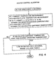
- a thermal model is used as depicted in the flowchart of Figure 4 and the associated source code shown in Appendix 2 of the aforementioned copending application of Lingane et al .
- RT1 and RT2 are numbers representing analog to digital converter counts, with each analog to digital converter count representing 20 millivolts.
- W_A_T is the Weighted Average Temperature
- C_C_T is the Calculated Cartridge Temperature.
- the temperature within the cartridge is calculated based on the ambient temperature (preferably inside the measurement instrument, but ambient temperature outside the instrument can be used) and the heater plate channel temperature and the passage of time.
- This model is continuously updated, and the results of the model are used to decide if the heating element is to be turned on or off, to maintain the cartridge temperature to approximately 35.3 ⁇ 0.5°C.
- thermistors are utilized to measure the temperatures used in the thermal model to calculate the temperature of the cartridge.
- the location of the sample detector is made quite close to the sample itself (typically approximately 0.4 cm), in direct contrast to the prior art which utilized optical transmission means such as mirrors in order to locate the detector at a distance (typically 10 cm) carefully selected such that the speckle size from the sample would be approximately equal to the size of the detector in order to maximize signal.
- the speckle size is much smaller than the size of the detector, providing significantly smaller signal levels (one embodiment signal levels are reduced by about a factor of about 200).
- greater gain is provided by electronic circuitry and a lower noise light source is utilized.
Landscapes
- Physics & Mathematics (AREA)
- Health & Medical Sciences (AREA)
- Life Sciences & Earth Sciences (AREA)
- Chemical & Material Sciences (AREA)
- Analytical Chemistry (AREA)
- Biochemistry (AREA)
- General Health & Medical Sciences (AREA)
- General Physics & Mathematics (AREA)
- Immunology (AREA)
- Pathology (AREA)
- Engineering & Computer Science (AREA)
- Quality & Reliability (AREA)
- Investigating Or Analysing Biological Materials (AREA)
- Automatic Analysis And Handling Materials Therefor (AREA)
Applications Claiming Priority (2)
| Application Number | Priority Date | Filing Date | Title |
|---|---|---|---|
| US34297289A | 1989-04-25 | 1989-04-25 | |
| US342972 | 1994-11-21 |
Publications (2)
| Publication Number | Publication Date |
|---|---|
| EP0395384A2 true EP0395384A2 (de) | 1990-10-31 |
| EP0395384A3 EP0395384A3 (de) | 1991-02-06 |
Family
ID=23344111
Family Applications (1)
| Application Number | Title | Priority Date | Filing Date |
|---|---|---|---|
| EP19900304461 Withdrawn EP0395384A3 (de) | 1989-04-25 | 1990-04-25 | System und Verfahren zum Modifizieren des Ausgangs eines Analysegeräts |
Country Status (4)
| Country | Link |
|---|---|
| EP (1) | EP0395384A3 (de) |
| JP (1) | JPH03505637A (de) |
| AU (1) | AU5387390A (de) |
| WO (1) | WO1990013035A1 (de) |
Cited By (3)
| Publication number | Priority date | Publication date | Assignee | Title |
|---|---|---|---|---|
| US5447440A (en) * | 1993-10-28 | 1995-09-05 | I-Stat Corporation | Apparatus for assaying viscosity changes in fluid samples and method of conducting same |
| EP0754944A1 (de) * | 1995-07-17 | 1997-01-22 | AVL Medical Instruments AG | Verfahren zur Qualitätskontrolle eines portablen Analysensystems sowie Flüssigkeit zur Durchführung des Verfahrens |
| WO2008127892A3 (en) * | 2007-04-12 | 2009-03-12 | Home Diagnostics Inc | Error detection and rejection for a diagnostic testing system |
Family Cites Families (16)
| Publication number | Priority date | Publication date | Assignee | Title |
|---|---|---|---|---|
| CH513393A (de) * | 1969-08-28 | 1971-09-30 | Greiner Electronic Ag | Verfahren zur reihenweisen Durchführung chemischer und/oder physikalischer Analysen |
| US3612321A (en) * | 1969-09-15 | 1971-10-12 | Bio Logics Inc | Container for biological fluids |
| US3644715A (en) * | 1969-09-22 | 1972-02-22 | Becton Dickinson Co | Machine readable label and sample identification system utilizing the same |
| US3794469A (en) * | 1970-03-02 | 1974-02-26 | Becton Dickinson Co | Blood test system |
| US3718439A (en) * | 1970-06-12 | 1973-02-27 | Instrumentation Labor Inc | Analytical apparatus |
| US3770382A (en) * | 1971-07-15 | 1973-11-06 | Du Pont | Automatic clinical analyzer |
| US3796239A (en) * | 1971-07-22 | 1974-03-12 | Instrumentation Labor Inc | Dispenser system |
| HU168257B (de) * | 1973-05-18 | 1976-03-28 | ||
| US3907503A (en) * | 1974-01-21 | 1975-09-23 | Miles Lab | Test system |
| DE3133826A1 (de) * | 1981-08-27 | 1983-03-10 | Boehringer Mannheim Gmbh, 6800 Mannheim | Analyseteststreifen und verfahren zu seiner herstellung |
| JPS6134669A (ja) * | 1984-07-27 | 1986-02-18 | Hitachi Ltd | 自動取引システム |
| CN1014551B (zh) * | 1986-09-16 | 1991-10-30 | 尼泰库株式会社 | 自动分析装置 |
| US4762594A (en) * | 1987-01-29 | 1988-08-09 | Medtest Systems, Inc. | Apparatus and methods for sensing fluid components |
| US4796884A (en) * | 1987-02-10 | 1989-01-10 | Coop Design, Inc. | Child's play set with a lift system |
| JPS6488764A (en) * | 1987-09-30 | 1989-04-03 | Toshiba Corp | Portable electronic equipment |
| AU5247790A (en) * | 1989-04-20 | 1990-10-25 | Biotrack, Inc. | Capillary flow device and reading instrument |
-
1990
- 1990-04-24 AU AU53873/90A patent/AU5387390A/en not_active Abandoned
- 1990-04-24 JP JP2507508A patent/JPH03505637A/ja active Pending
- 1990-04-24 WO PCT/US1990/002214 patent/WO1990013035A1/en not_active Ceased
- 1990-04-25 EP EP19900304461 patent/EP0395384A3/de not_active Withdrawn
Cited By (9)
| Publication number | Priority date | Publication date | Assignee | Title |
|---|---|---|---|---|
| US5447440A (en) * | 1993-10-28 | 1995-09-05 | I-Stat Corporation | Apparatus for assaying viscosity changes in fluid samples and method of conducting same |
| US5628961A (en) * | 1993-10-28 | 1997-05-13 | I-Stat Corporation | Apparatus for assaying viscosity changes in fluid samples and method of conducting same |
| EP0754944A1 (de) * | 1995-07-17 | 1997-01-22 | AVL Medical Instruments AG | Verfahren zur Qualitätskontrolle eines portablen Analysensystems sowie Flüssigkeit zur Durchführung des Verfahrens |
| WO2008127892A3 (en) * | 2007-04-12 | 2009-03-12 | Home Diagnostics Inc | Error detection and rejection for a diagnostic testing system |
| EP2175269A1 (de) | 2007-04-12 | 2010-04-14 | Home Diagnostics, Inc. | Fehlererkennung und -unterdrückung für ein Diagnosetestsystem |
| US9029157B2 (en) | 2007-04-12 | 2015-05-12 | Nipro Diagnostics, Inc. | Error detection and rejection for a diagnostic testing system |
| US10013297B2 (en) | 2007-04-12 | 2018-07-03 | Trividia Health, Inc. | Error detection and rejection for a diagnostic testing system |
| US10459781B2 (en) | 2007-04-12 | 2019-10-29 | Trividia Health, Inc. | Error detection and rejection for a diagnostic testing system |
| US11327823B2 (en) | 2007-04-12 | 2022-05-10 | Trividia Health, Inc. | Error detection and rejection for a diagnostic testing system |
Also Published As
| Publication number | Publication date |
|---|---|
| JPH03505637A (ja) | 1991-12-05 |
| EP0395384A3 (de) | 1991-02-06 |
| WO1990013035A1 (en) | 1990-11-01 |
| AU5387390A (en) | 1990-11-01 |
Similar Documents
| Publication | Publication Date | Title |
|---|---|---|
| US5410474A (en) | Buttonless memory system for an electronic measurement device | |
| EP0488994B1 (de) | Qualitätssicherunggerät zur Verwendung in einem analytischen Instrument | |
| US5686659A (en) | Fluid dose flow and coagulation sensor for medical instrument | |
| US7212925B2 (en) | Calibration data entry system for a test instrument | |
| EP1009981B1 (de) | Vorrichtung zur funktionsprüfung von optischen systemen für die klinische analyse | |
| KR100540849B1 (ko) | 생체물질을 정량적으로 분석하는 장치 | |
| EP0451981A2 (de) | Reagenzeinheit zum Einmalgebrauch | |
| EP1054805B1 (de) | Vorrichtung zum füllen mittels kapillar-aktion | |
| KR19980024133A (ko) | 테스트 키트 및 장치 | |
| EP0283285A2 (de) | Verfahren und Vorrichtung zur Überwachung von Analyten in Flüssigkeiten | |
| CZ2003282A3 (cs) | Způsob a zařízení pro detekci přítomnosti tekutiny na zkušebním proužku | |
| EP1588161B1 (de) | System und verfahren zur messung vonkoagulationszeit ohne thermostatische steuerung | |
| JPS59206744A (ja) | 遠心分析装置 | |
| JP2004138619A (ja) | 試験線条体の過少配量の検出および補償方法 | |
| EP0394041A2 (de) | Kapillärdurchflussgerät und Ablesevorrichtung | |
| JPH11142412A (ja) | 自動分析装置 | |
| Marlar et al. | Sources and solutions for spurious test results in coagulation | |
| WO1990013035A1 (en) | System for modifying output of an analytical instrument | |
| Sterling et al. | Simultaneous patient-side measurement of hemoglobin, glucose, and cholesterol in finger-stick blood | |
| CA1062501A (en) | Method and apparatus for determining deficiencies in enzymatic reactions particularly clotting factor levels in blood plasma | |
| Ng | Selecting Instrumentation for Physician’s Office Testing | |
| Drewinko et al. | Evaluation of automatic and semiautomatic coagulation assay instruments | |
| Witte et al. | Bichromatic Analysis: The Design and | |
| Galimany | Bedside Chemistry | |
| WO1994017212A1 (en) | Slide immunoassay detection system |
Legal Events
| Date | Code | Title | Description |
|---|---|---|---|
| PUAI | Public reference made under article 153(3) epc to a published international application that has entered the european phase |
Free format text: ORIGINAL CODE: 0009012 |
|
| AK | Designated contracting states |
Kind code of ref document: A2 Designated state(s): AT BE CH DE DK ES FR GB GR IT LI LU NL SE |
|
| PUAL | Search report despatched |
Free format text: ORIGINAL CODE: 0009013 |
|
| RHK1 | Main classification (correction) |
Ipc: B01L 3/00 |
|
| AK | Designated contracting states |
Kind code of ref document: A3 Designated state(s): AT BE CH DE DK ES FR GB GR IT LI LU NL SE |
|
| 17P | Request for examination filed |
Effective date: 19910412 |
|
| STAA | Information on the status of an ep patent application or granted ep patent |
Free format text: STATUS: THE APPLICATION HAS BEEN WITHDRAWN |
|
| 18W | Application withdrawn |
Withdrawal date: 19911021 |
|
| R18W | Application withdrawn (corrected) |
Effective date: 19911021 |