EP0395847A2 - Assemblage d'entraînement pour un toit pliant entraîné par moteur - Google Patents
Assemblage d'entraînement pour un toit pliant entraîné par moteur Download PDFInfo
- Publication number
- EP0395847A2 EP0395847A2 EP90103292A EP90103292A EP0395847A2 EP 0395847 A2 EP0395847 A2 EP 0395847A2 EP 90103292 A EP90103292 A EP 90103292A EP 90103292 A EP90103292 A EP 90103292A EP 0395847 A2 EP0395847 A2 EP 0395847A2
- Authority
- EP
- European Patent Office
- Prior art keywords
- drive
- lever
- motor
- main bow
- bracket
- Prior art date
- Legal status (The legal status is an assumption and is not a legal conclusion. Google has not performed a legal analysis and makes no representation as to the accuracy of the status listed.)
- Granted
Links
- 230000005540 biological transmission Effects 0.000 claims abstract description 4
- 230000001419 dependent effect Effects 0.000 claims abstract description 3
- 238000006073 displacement reaction Methods 0.000 claims description 2
- 230000004308 accommodation Effects 0.000 description 1
- 239000002184 metal Substances 0.000 description 1
- 238000012986 modification Methods 0.000 description 1
- 230000004048 modification Effects 0.000 description 1
Images

Classifications
-
- B—PERFORMING OPERATIONS; TRANSPORTING
- B60—VEHICLES IN GENERAL
- B60J—WINDOWS, WINDSCREENS, NON-FIXED ROOFS, DOORS, OR SIMILAR DEVICES FOR VEHICLES; REMOVABLE EXTERNAL PROTECTIVE COVERINGS SPECIALLY ADAPTED FOR VEHICLES
- B60J7/00—Non-fixed roofs; Roofs with movable panels, e.g. rotary sunroofs
- B60J7/08—Non-fixed roofs; Roofs with movable panels, e.g. rotary sunroofs of non-sliding type, i.e. movable or removable roofs or panels, e.g. let-down tops or roofs capable of being easily detached or of assuming a collapsed or inoperative position
- B60J7/12—Non-fixed roofs; Roofs with movable panels, e.g. rotary sunroofs of non-sliding type, i.e. movable or removable roofs or panels, e.g. let-down tops or roofs capable of being easily detached or of assuming a collapsed or inoperative position foldable; Tensioning mechanisms therefor, e.g. struts
- B60J7/1226—Soft tops for convertible vehicles
- B60J7/1265—Soft tops for convertible vehicles characterised by kinematic movements, e.g. using parallelogram linkages
- B60J7/1269—Soft tops for convertible vehicles characterised by kinematic movements, e.g. using parallelogram linkages with remote power control
-
- Y—GENERAL TAGGING OF NEW TECHNOLOGICAL DEVELOPMENTS; GENERAL TAGGING OF CROSS-SECTIONAL TECHNOLOGIES SPANNING OVER SEVERAL SECTIONS OF THE IPC; TECHNICAL SUBJECTS COVERED BY FORMER USPC CROSS-REFERENCE ART COLLECTIONS [XRACs] AND DIGESTS
- Y10—TECHNICAL SUBJECTS COVERED BY FORMER USPC
- Y10T—TECHNICAL SUBJECTS COVERED BY FORMER US CLASSIFICATION
- Y10T74/00—Machine element or mechanism
- Y10T74/20—Control lever and linkage systems
- Y10T74/20207—Multiple controlling elements for single controlled element
- Y10T74/20213—Interconnected
Definitions
- the invention relates to a drive device for a motor-driven folding roof for motor vehicles, which essentially consists of a front and a rear roof frame, a main bow articulated by means of a bracket on the vehicle body, a storm rod supporting this, as well as a tensioning linkage and a motor drive Includes a transmission device for successive loading of the main bow and the clamping bracket with the driving force of the motor drive.
- the invention is therefore based on the object of providing a drive device for a motor-driven folding top for motor vehicles which manages with a single and simple drive motor and can be accommodated at a suitable location within the vehicle body and which can also be implemented with the least possible production and assembly effort.
- the tensioning bracket and the main bow each have a push rod and a lever rotatably mounted about a fixed axis with a shaft driven by a drive motor in a geared drive connection, the two levers being pivotable about axes which are not concentric with one another are stored and drive-dependent depending on the path.
- the use of a push rod in connection with a rotatably mounted lever for driving both the main bow and the tensioning bracket allows only those of the two levers which are assigned to the part with the largest required adjustment path, i.e. the main bow, to connect the motor drive in a rotationally secure manner and to drive the lever assigned to the other part, i.e.
- the tensioning bracket by means of a towing device only over a certain angular amount required for the movement of the tensioning bracket by the lever assigned to the adjustment of the main bow, the use of a simple towing device avoiding the use of complex transmission devices.
- the use of push rods to connect the parts to be driven, main bow and tensioning bracket, with the drive motor also enables it to be accommodated at a convenient location within the vehicle body.
- the lever assigned to the drive of the main bow is secured against rotation with that driven by the motor Shaft is coupled and the lever assigned to the drive of the tensioning bracket is designed as a rocker arm and has two arms and is provided on its free lever arm with a driver or towing device which is effective in both directions of movement.
- the offset of the bearing axes of the two levers is to be dimensioned larger in a horizontal direction than the effective length of the driver or drag device on the free lever arm of the lever assigned to the drive of the tensioning lever in one direction of movement.
- Towing device is expediently provided that the two lever arms of the lever assigned to the drive of the clamping bracket are aligned at right angles to one another and that the driver device on the free lever arm of this lever, depending on the axial displacement of the bearing axles of the two levers, is designed such that it is asymmetrical in that Raising the clamp associated movement direction is effective only over a certain angular adjustment of the lever.
- the driver or towing device formed on the free lever arm of the lever assigned to the drive of the tensioning bracket is expediently formed by an essentially U-shaped cross-sectional configuration of the lever arm. This can be realized particularly advantageously by the two levers being formed by simple sheet-metal pressed profiles.
- the two levers are arranged in two superimposed levels and that the rocker arm assigned to the drive of the tensioning bracket is arranged below the drive lever for the main bow and that the effective lever arms of the two levers have different lengths, wherein the lever arm assigned to the drive of the tensioning bracket has a greater length than the lever arm assigned to the drive of the main bow.
- the drive device is expediently designed such that the lever assigned to the drive of the main bow is driven by an electric motor by means of an angular gear rotating about its bearing axis.
- the drive device can also be provided in a modification that the lever associated with the drive of the main bow is driven by means of a coaxially arranged ring gear and a rack by a linear drive motor.
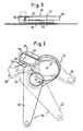
- a front 1 and a rear roof frame 2 are pivotally connected to one another about an axis 3 running transversely to the direction of travel, and the rear roof frame 2 is also connected to a main bow 5 at the other end also pivotably about an axis 4 running transversely to the direction of travel , which in turn is articulated about an axis 6 extending transversely to the direction of travel on brackets 7 fastened to the vehicle body 8.
- Parallel to the articulation axis 6 of the main bow 5 is a clamping bracket with this 9 pivotally connected, the main bow 5 being supported against the tensioning bracket 9 by means of a storm bar 12 consisting of two parts 10 and 11 which can be pivoted against one another when the top is closed.
- the main bow 5 is connected by a push rod 13 and the tensioning bracket 9 by a further push rod 14 to a drive motor 15 arranged in the area of the trunk of the vehicle body 8.
- a drive device 16 is provided downstream of the drive motor 15, which essentially has two levers 19 and 20 which are rotatably displaceable about axes 17 and 18 which are not concentric with one another, one lever 19 of which with the push rod 13 for the drive of the main bow 5 and its other lever 20 is connected to the push rod 14 for driving the clamping bracket 9.
- the lever 19 connected to the push rod 13 for driving the main bow 5 is rotatably mounted on the driven shaft 21, which at the same time also forms its bearing axis 17 and which is in drive connection with the drive motor 15 by means of an angular gear 22.
- the lever 20 connected to the push rod 14 for driving the tensioning bracket 9 is in turn freely rotatably mounted on a bearing shaft 18 which is fixed and laterally offset from the shaft 17 and is designed as a double-armed lever, being connected to the push rod 14 via its one lever arm 23 and on its other, free lever arm 24 a driver or.
- Towing device 25 is essentially formed by a U-shaped cross-sectional design of the free lever arm 24 and is designed asymmetrically such that the part 26 of the driving or.
- the towing device 25 is only engaged behind by the lever 19 assigned to the drive of the main bow 5 over a certain angle of rotation range, while the other part 27 of the driver or.
- Towing device has a length that ensures that the lever 20 is carried along until the main bow 5 is completely folded.
- the two lever arms 23 and 24 of the double-arm lever 20 are aligned at right angles to one another.
- the two levers 19 and 20 are also, as can be seen in particular from the illustration in FIG. 3, arranged in two superimposed levels and in such a way that the lever 20 assigned to the drive of the tensioning bracket 9 engages under the lever 19 assigned to the drive of the main bow 5 or in the region engages around the driver or towing device 25.
Landscapes
- Engineering & Computer Science (AREA)
- Mechanical Engineering (AREA)
- Body Structure For Vehicles (AREA)
- Power-Operated Mechanisms For Wings (AREA)
- Lock And Its Accessories (AREA)
Applications Claiming Priority (2)
| Application Number | Priority Date | Filing Date | Title |
|---|---|---|---|
| DE8905574U | 1989-05-03 | ||
| DE8905574U DE8905574U1 (de) | 1989-05-03 | 1989-05-03 | Antriebseinrichtung für ein motorisch antreibbares Klappverdeck |
Publications (3)
| Publication Number | Publication Date |
|---|---|
| EP0395847A2 true EP0395847A2 (fr) | 1990-11-07 |
| EP0395847A3 EP0395847A3 (fr) | 1991-07-03 |
| EP0395847B1 EP0395847B1 (fr) | 1993-05-05 |
Family
ID=6838912
Family Applications (1)
| Application Number | Title | Priority Date | Filing Date |
|---|---|---|---|
| EP90103292A Expired - Lifetime EP0395847B1 (fr) | 1989-05-03 | 1990-02-21 | Assemblage d'entraînement pour un toit pliant entraîné par moteur |
Country Status (4)
| Country | Link |
|---|---|
| US (1) | US5042868A (fr) |
| EP (1) | EP0395847B1 (fr) |
| DE (2) | DE8905574U1 (fr) |
| ES (1) | ES2039974T3 (fr) |
Families Citing this family (27)
| Publication number | Priority date | Publication date | Assignee | Title |
|---|---|---|---|---|
| US5225747A (en) | 1992-01-06 | 1993-07-06 | Asc Incorporated | Single-button actuated self-correcting automatic convertible top |
| US5673959B1 (en) * | 1994-11-28 | 2000-05-02 | Craig W Padlo | Foldable convertible flexible-roof support |
| DE4443405B4 (de) * | 1994-12-07 | 2005-05-25 | Edscha Cabrio-Dachsysteme Gmbh | Antriebseinrichtung für ein Kraftfahrzeug-Faltverdeck |
| NL9500543A (nl) * | 1995-03-21 | 1996-11-01 | Applied Power Inc | Motorvoertuig met vouwdak en vouwdak voor een dergelijk motorvoertuig. |
| EP0749859B1 (fr) * | 1995-06-22 | 2000-03-22 | Wilhelm Karmann GmbH | Capote pliante pour véhicule convertible |
| US5620226A (en) * | 1995-12-07 | 1997-04-15 | Dura Convertible Systems, Inc. | Simplified automated top operator |
| DE19622953C1 (de) * | 1996-06-07 | 1997-08-07 | Porsche Ag | Faltverdeck für ein Fahrzeug, insbesondere Personenkraftwagen |
| US6295713B1 (en) | 1996-10-22 | 2001-10-02 | Chrysler Corporation | Method for attaching a soft top to a motor vehicle body |
| US5947546A (en) * | 1996-10-22 | 1999-09-07 | Chrysler Corporation | Apparatus for attaching a soft top to a motor vehicle |
| US5992917A (en) * | 1996-10-22 | 1999-11-30 | Chrysler Corporation | Top system for a motor vehicle |
| US6036256A (en) * | 1996-10-22 | 2000-03-14 | Chrysler Corporation | Window assembly for a motor vehicle |
| US6073989A (en) * | 1996-10-22 | 2000-06-13 | Daimlerchrysler Corporation | Removable door frame assembly for a motor vehicle |
| US5979969A (en) * | 1997-10-22 | 1999-11-09 | Chrysler Corporation | Apparatus for selectively mounting a hard top and a soft top to a motor vehicle |
| FI107718B (fi) * | 1998-02-27 | 2001-09-28 | Valmet Automotive Oy | Ajoneuvo ja avattava katto ajoneuvoa varten |
| US6048021A (en) * | 1998-04-25 | 2000-04-11 | Dura Convertible Systems | Convertible top mechanism with powered rear row |
| DE19942427B4 (de) * | 1999-09-06 | 2006-11-09 | Webasto Ag | Faltverdeck für ein Cabriolet |
| DE19963640C1 (de) * | 1999-12-29 | 2001-08-16 | Cts Fahrzeug Dachsysteme Gmbh | Zwischen einer Schließstellung und einer Ablagestellung verstellbares Fahrzeugdach |
| US6283531B1 (en) * | 2000-08-07 | 2001-09-04 | Honda Giken Kogyo Kabushiki Kaisha | Vehicle including electric folding roof |
| DE10112092C1 (de) * | 2001-03-12 | 2002-08-08 | Cts Fahrzeug Dachsysteme Gmbh | Zwischen einer Schließposition und einer Öffnungsposition verstellbares Cabriolet-Fahrzeugdach |
| US6629719B2 (en) * | 2001-09-26 | 2003-10-07 | Asc Incorporated | Top stack mechanism for a convertible roof |
| DE10157819B4 (de) * | 2001-11-27 | 2005-03-10 | Cts Fahrzeug Dachsysteme Gmbh | Verstellbares Fahrzeugdach mit einem Faltverdeck |
| DE10248344A1 (de) * | 2002-10-17 | 2004-05-06 | Wilhelm Karmann Gmbh | Kraftfahrzeug |
| US6964340B2 (en) * | 2003-04-18 | 2005-11-15 | Wilhelm Karmann Gmbh | Retractable hardtop with articulating center panel |
| US6966599B2 (en) * | 2003-06-30 | 2005-11-22 | Asc Incorporated | Convertible roof apparatus with power roof bow linked to a tensioning bow |
| US7032951B2 (en) * | 2004-02-26 | 2006-04-25 | Asc. Incorporated | Convertible vehicle top stack mechanism |
| US7100962B2 (en) * | 2005-01-11 | 2006-09-05 | Asc Incorporated | Convertible roof bow control mechanism |
| DE102010013009B4 (de) | 2010-03-26 | 2016-02-25 | Magna Car Top Systems Gmbh | Verdeckantrieb und Cabrioletfahrzeug |
Family Cites Families (7)
| Publication number | Priority date | Publication date | Assignee | Title |
|---|---|---|---|---|
| BE411584A (fr) * | 1925-07-22 | |||
| CH192466A (fr) * | 1934-10-27 | 1937-08-15 | Bessonneau Maurice | Carrosserie à capote escamotable pour véhicule. |
| GB616691A (en) * | 1946-09-25 | 1949-01-25 | Carbodies Ltd | Folding hood for motor-vehicles and the like |
| DE2327486C2 (de) * | 1973-05-30 | 1975-04-30 | Daimler-Benz Ag, 7000 Stuttgart | Steuerung eines an versenkt angeordneten Konsolen angelenkten Gestänges eines Klappverdeckes von Kraftfahrzeugen |
| JPS61249815A (ja) * | 1985-04-27 | 1986-11-07 | Mazda Motor Corp | 自動車の移動屋根装置 |
| DE3709927A1 (de) * | 1987-03-26 | 1988-10-06 | Porsche Ag | Klappverdeck fuer personenwagen |
| CA1327827C (fr) * | 1987-08-04 | 1994-03-15 | Masaya Horikawa | Dispositif d'entrainement relie au mecanisme d'ouverture/fermeture du toit d'un vehicule |
-
1989
- 1989-05-03 DE DE8905574U patent/DE8905574U1/de not_active Expired
-
1990
- 1990-02-21 DE DE9090103292T patent/DE59001341D1/de not_active Expired - Fee Related
- 1990-02-21 ES ES199090103292T patent/ES2039974T3/es not_active Expired - Lifetime
- 1990-02-21 EP EP90103292A patent/EP0395847B1/fr not_active Expired - Lifetime
- 1990-05-02 US US07/517,822 patent/US5042868A/en not_active Expired - Fee Related
Also Published As
| Publication number | Publication date |
|---|---|
| DE8905574U1 (de) | 1989-10-12 |
| EP0395847A3 (fr) | 1991-07-03 |
| EP0395847B1 (fr) | 1993-05-05 |
| DE59001341D1 (de) | 1993-06-09 |
| ES2039974T3 (es) | 1993-10-01 |
| US5042868A (en) | 1991-08-27 |
Similar Documents
| Publication | Publication Date | Title |
|---|---|---|
| EP0395847B1 (fr) | Assemblage d'entraînement pour un toit pliant entraîné par moteur | |
| DE2942006C2 (de) | Schiebedach für Kraftfahrzeuge | |
| DE2724457C3 (de) | Zusammenschiebbares Dach eines Fahrzeugs | |
| DE1946161C3 (de) | Schiebedach für Kraftfahrzeuge | |
| EP0860311A1 (fr) | Coffre de stockage variable pour capote de cabriolet | |
| DE4443405A1 (de) | Antriebseinrichtung für ein Kraftfahrzeug-Faltverdeck | |
| DE68907692T2 (de) | Schiebedachaufbau für ein Fahrzeug. | |
| DE19828464C1 (de) | Vorrichtung zur Betätigung eines Hebe-Schiebedaches | |
| EP1080965B1 (fr) | Dispositif d'entraînement pour élément pivotant | |
| EP2644423A2 (fr) | Déflecteur d'air | |
| DE4316253A1 (de) | Vorrichtung zur Bewegung einer Schwenkschiebetür für Fahrzeuge zur Personenbeförderung, insbesondere Schienenfahrzeuge | |
| DE102006023911A1 (de) | Vorrichtung zum Führen der Bewegung eines Windabweisers | |
| DE4326291C2 (de) | Fahrzeugdach | |
| DE3129900C2 (de) | Hebeschiebedach für Kraftfahrzeuge | |
| DE2139086A1 (de) | Fensterheber für vertikal unterteilte Türfenster von Kraftfahrzeugen | |
| EP0716004A1 (fr) | Porte pivotante et coulissante pour véhicules de transport de personnes | |
| DE19634324C2 (de) | Fahrzeugdach | |
| DE2507893B2 (de) | Fensterheber für vertikal unterteilte Kraftfahrzeugschiebefenster | |
| DE3310502C2 (de) | Führungsvorrichtung für ein Schiebedach oder Schiebehebedach mit Mittelantrieb | |
| DE102004042450B4 (de) | Fahrzeugdach | |
| DE102008045904B3 (de) | Kraftfahrzeug mit Mechanismus zum Bewegen einer Klappe mittels eines Motors | |
| EP1676735B1 (fr) | Système store à enrouleur pour une vitre latérale triangulaire de véhicule | |
| DE102021118663A1 (de) | Bodenfräsmaschine | |
| DE3878644T2 (de) | Schiebedach fuer ein kraftfahrzeug. | |
| DE2529556A1 (de) | Vorrichtung zur einstellung eines fahrzeugsitzes |
Legal Events
| Date | Code | Title | Description |
|---|---|---|---|
| PUAI | Public reference made under article 153(3) epc to a published international application that has entered the european phase |
Free format text: ORIGINAL CODE: 0009012 |
|
| AK | Designated contracting states |
Kind code of ref document: A2 Designated state(s): DE ES FR GB IT NL SE |
|
| 17P | Request for examination filed |
Effective date: 19901220 |
|
| PUAL | Search report despatched |
Free format text: ORIGINAL CODE: 0009013 |
|
| AK | Designated contracting states |
Kind code of ref document: A3 Designated state(s): DE ES FR GB IT NL SE |
|
| 17Q | First examination report despatched |
Effective date: 19921014 |
|
| GRAA | (expected) grant |
Free format text: ORIGINAL CODE: 0009210 |
|
| AK | Designated contracting states |
Kind code of ref document: B1 Designated state(s): DE ES FR GB IT NL SE |
|
| ET | Fr: translation filed | ||
| GBT | Gb: translation of ep patent filed (gb section 77(6)(a)/1977) |
Effective date: 19930506 |
|
| REF | Corresponds to: |
Ref document number: 59001341 Country of ref document: DE Date of ref document: 19930609 |
|
| ITF | It: translation for a ep patent filed | ||
| REG | Reference to a national code |
Ref country code: ES Ref legal event code: FG2A Ref document number: 2039974 Country of ref document: ES Kind code of ref document: T3 |
|
| PLBE | No opposition filed within time limit |
Free format text: ORIGINAL CODE: 0009261 |
|
| STAA | Information on the status of an ep patent application or granted ep patent |
Free format text: STATUS: NO OPPOSITION FILED WITHIN TIME LIMIT |
|
| 26N | No opposition filed | ||
| PGFP | Annual fee paid to national office [announced via postgrant information from national office to epo] |
Ref country code: DE Payment date: 19950124 Year of fee payment: 6 |
|
| EAL | Se: european patent in force in sweden |
Ref document number: 90103292.0 |
|
| PGFP | Annual fee paid to national office [announced via postgrant information from national office to epo] |
Ref country code: GB Payment date: 19951222 Year of fee payment: 7 |
|
| PGFP | Annual fee paid to national office [announced via postgrant information from national office to epo] |
Ref country code: SE Payment date: 19960227 Year of fee payment: 7 |
|
| PGFP | Annual fee paid to national office [announced via postgrant information from national office to epo] |
Ref country code: FR Payment date: 19960228 Year of fee payment: 7 |
|
| PGFP | Annual fee paid to national office [announced via postgrant information from national office to epo] |
Ref country code: NL Payment date: 19960229 Year of fee payment: 7 |
|
| PG25 | Lapsed in a contracting state [announced via postgrant information from national office to epo] |
Ref country code: DE Effective date: 19961101 |
|
| PGFP | Annual fee paid to national office [announced via postgrant information from national office to epo] |
Ref country code: ES Payment date: 19970214 Year of fee payment: 8 |
|
| PG25 | Lapsed in a contracting state [announced via postgrant information from national office to epo] |
Ref country code: GB Effective date: 19970221 |
|
| PG25 | Lapsed in a contracting state [announced via postgrant information from national office to epo] |
Ref country code: SE Effective date: 19970222 |
|
| PG25 | Lapsed in a contracting state [announced via postgrant information from national office to epo] |
Ref country code: NL Effective date: 19970901 |
|
| GBPC | Gb: european patent ceased through non-payment of renewal fee |
Effective date: 19970221 |
|
| PG25 | Lapsed in a contracting state [announced via postgrant information from national office to epo] |
Ref country code: FR Effective date: 19971030 |
|
| EUG | Se: european patent has lapsed |
Ref document number: 90103292.0 |
|
| NLV4 | Nl: lapsed or anulled due to non-payment of the annual fee |
Effective date: 19970901 |
|
| REG | Reference to a national code |
Ref country code: FR Ref legal event code: ST |
|
| PG25 | Lapsed in a contracting state [announced via postgrant information from national office to epo] |
Ref country code: ES Free format text: LAPSE BECAUSE OF NON-PAYMENT OF DUE FEES Effective date: 19980223 |
|
| REG | Reference to a national code |
Ref country code: ES Ref legal event code: FD2A Effective date: 20000403 |
|
| PG25 | Lapsed in a contracting state [announced via postgrant information from national office to epo] |
Ref country code: IT Free format text: LAPSE BECAUSE OF NON-PAYMENT OF DUE FEES;WARNING: LAPSES OF ITALIAN PATENTS WITH EFFECTIVE DATE BEFORE 2007 MAY HAVE OCCURRED AT ANY TIME BEFORE 2007. THE CORRECT EFFECTIVE DATE MAY BE DIFFERENT FROM THE ONE RECORDED. Effective date: 20050221 |