EP0395863B1 - Radiomètre à ouverture synthétisée utilisant une technique numérique de concentration du faisceau - Google Patents
Radiomètre à ouverture synthétisée utilisant une technique numérique de concentration du faisceau Download PDFInfo
- Publication number
- EP0395863B1 EP0395863B1 EP90104989A EP90104989A EP0395863B1 EP 0395863 B1 EP0395863 B1 EP 0395863B1 EP 90104989 A EP90104989 A EP 90104989A EP 90104989 A EP90104989 A EP 90104989A EP 0395863 B1 EP0395863 B1 EP 0395863B1
- Authority
- EP
- European Patent Office
- Prior art keywords
- signals
- coupled
- fanbeam
- digital
- scene
- Prior art date
- Legal status (The legal status is an assumption and is not a legal conclusion. Google has not performed a legal analysis and makes no representation as to the accuracy of the status listed.)
- Expired - Lifetime
Links
Images

Classifications
-
- H—ELECTRICITY
- H01—ELECTRIC ELEMENTS
- H01Q—ANTENNAS, i.e. RADIO AERIALS
- H01Q3/00—Arrangements for changing or varying the orientation or the shape of the directional pattern of the waves radiated from an antenna or antenna system
- H01Q3/26—Arrangements for changing or varying the orientation or the shape of the directional pattern of the waves radiated from an antenna or antenna system varying the relative phase or relative amplitude of energisation between two or more active radiating elements; varying the distribution of energy across a radiating aperture
- H01Q3/2605—Array of radiating elements provided with a feedback control over the element weights, e.g. adaptive arrays
-
- G—PHYSICS
- G01—MEASURING; TESTING
- G01N—INVESTIGATING OR ANALYSING MATERIALS BY DETERMINING THEIR CHEMICAL OR PHYSICAL PROPERTIES
- G01N22/00—Investigating or analysing materials by the use of microwaves or radio waves, i.e. electromagnetic waves with a wavelength of one millimetre or more
-
- G—PHYSICS
- G01—MEASURING; TESTING
- G01S—RADIO DIRECTION-FINDING; RADIO NAVIGATION; DETERMINING DISTANCE OR VELOCITY BY USE OF RADIO WAVES; LOCATING OR PRESENCE-DETECTING BY USE OF THE REFLECTION OR RERADIATION OF RADIO WAVES; ANALOGOUS ARRANGEMENTS USING OTHER WAVES
- G01S3/00—Direction-finders for determining the direction from which infrasonic, sonic, ultrasonic or electromagnetic waves, or particle emission, not having a directional significance, are being received
- G01S3/02—Direction-finders for determining the direction from which infrasonic, sonic, ultrasonic or electromagnetic waves, or particle emission, not having a directional significance, are being received using radio waves
-
- H—ELECTRICITY
- H01—ELECTRIC ELEMENTS
- H01Q—ANTENNAS, i.e. RADIO AERIALS
- H01Q25/00—Antennas or antenna systems providing at least two radiating patterns
- H01Q25/004—Antennas or antenna systems providing at least two radiating patterns providing two or four symmetrical beams for Janus application
Definitions
- the present invention relates generally to digital aperture synthesized radiometers, and more particularly to an aperture synthesized radiometer employing digital beamforming including interferometry and which is capable of imaging microwave energy emitted or reflected by earth surface features.
- Microwave radiometers are passive remote sensors which can be designed to detect, measure and display the microwave energy emitted by earth surface features and the atmosphere. Such systems, operating at L-band, can be used for soil moisture measurements from a space platform orbiting the earth.
- a microwave radiometer which reconstructs images using fanbeam inversion.
- a scanning radiometer utilizes a fanbeam antenna which is mechanically scanned across the scene so that the antenna output is a projection of the scene taken along the direction of the scan. The scanning motion is provided for by a motor coupled to the antenna and controlled by a computer. An inverse Radon transform is employed in the computer to reconstruct the scene.
- an aperture synthesized radiometer comprises:
- a method of digitally processing an image comprises the steps of:
- the present invention is an alternative to the above-described scanning radiometer system, and it provides for an aperture synthesized radiometer comprising a plurality of substantially parallel antenna arrays for receiving radiation emitted or reflected from an scene, and an analog to digital converter coupled to the plurality of antenna arrays for converting received radiation into corresponding digitized signals.
- a digital imaging processor is coupled to the analog to digital converter for processing and synthesizing the digitized signals to synthesize a large aperture antenna array which provides an image corresponding to the scene.
- the digital imaging processor comprises individual digital beamformers coupled to each of the antenna arrays for generating a set of fanbeam signals for each antenna array.
- the beamformers provide for cross track imaging of the scene.
- a digital correlating interferometer is coupled to the individual beamformers for convening the sets of fanbeam signals into spot beam images.
- the digital interferometer correlates corresponding pairs of fanbeam signals from the two sets of fanbeam signals to produce a slowly varying chirp signal from the images of a given spot on the earth's surface as a space platform on which the radiometer is disposed moves relative to the earth's surface. This provides for along track imaging of the scene.
- a matched filter is used to transform the slowly varying chirp signals from the output of the digital interferometer into corresponding image points of the scene within each fanbeam.
- the individual digital beamformers further comprise an amplitude weighting circuit which provides for amplitude weighting of the digitized radiation signals to reduce fanbeam signal sidelobe levels. Also, a data turning circuit is coupled to the amplitude weighting circuit to eliminate alternate mainlobes from the digitized signals. This reduces mainlobe widening of the digitized signals.
- the individual digital beamformers each comprise a fast Fourier transform circuit which transforms the digitized signals into the fanbeam signals.
- the fast Fourier transform circuit generally comprises a decimation-in-time algorithm implemented by means of a plurality of parallel and cascaded butterfly computation circuits.
- the present invention provides for a digital aperture synthesized radiometer that achieves remote sensing and imaging of microwave energy.
- the present invention also comprises a method of digitally processing an image.
- the method comprises the steps of receiving radiation emitted or reflected from an scene. This is done by means of a plurality of substantially parallel antenna arrays.
- the next step involves converting received radiation into corresponding digitized signals. This is accomplished by means of an analog to digital converter coupled to the plurality of antenna arrays.
- the method provides for processing and synthesizing the digitized signals to provide an image corresponding to the scene. This is achieved by means of a digital imaging processor coupled to the analog to digital converter.
- the synthesizing step generally comprises processing and synthesizing the digitized signals which is performed by means of individual digital beamformers coupled to two antenna arrays, and generating a set of fanbeam signals for each antenna array utilizing fast Fourier transforms. This step provides for cross track imaging of the scene. Pairs of fanbeam signals from the beamformers are then correlated. This step is performed by means of a digital interferometer coupled to the individual beamformers.
- this process step generates a slowly varying chirp signal for each pair of fanbeam signals for a point source image within the fanbeam.
- the chirp signals are then processed by means of matched filter coupled to the digital interferometer to transform each chirp signal into a corresponding point image intensity in the scene.
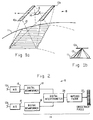
- an aperture synthesized radiometer 10 in accordance with the present invention and employed in an operational environment of a space platform orbiting the earth 11 is shown.
- the aperture synthesized radiometer 10 comprises two linear active receiving antennas 12a, 12b, each of which comprise linear array antennas.
- An imaging processor 14 comprises a digital beamforming processor which operates as the central imaging processing unit of the radiometer 10, a digital correlating interferometer and a matched filter, all of which will be discussed in detail hereinbelow.
- the antennas 12 generate fanbeams 13 that provide for cross track resolution of the scene, since the antennas 12 are oriented transverse to the direction of travel (v) of the space platform relative to the earth. Along track resolution is provided by the interferometer and matched filter combination.
- FIG. 2 a block diagram of the synthetic aperture radiometer 10 of the present invention is shown.
- the two linear active receiving antennas 12a, 12b are coupled by way of separate analog to digital converters 16 to the imaging processor 14.
- the imaging processor 14 includes two digital beamforming processors 18 whose outputs are coupled to a digital correlating interferometer 20, and the output of the interferometer 20 is coupled to a matched filter 22 which provides the digital output image of the radiometer 10, in the form of cross track pixels.
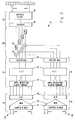
- FIG. 3 provides a more detailed diagram of the radiometer 10. As shown therein, the antenna elements of each antenna 12 are coupled by way of a sample and hold circuit 24 and an analog multiplexer 26 to an analog to digital converter circuit 28. The analog to digital converter circuit 28 provides a parallel set of outputs to each digital beamforming processor 18.
- Each digital beamforming processor 18 comprises an amplitude weighting and data turning circuit 32.
- the amplitude weighting and data turning circuit is coupled to a digital Fourier transform circuit 34 which embodies a fast Fourier transform algorithm in hardware form.
- the digital Fourier transform circuit 34 is adapted to perform a 128 point fast Fourier transform of the data received thereby.
- Each fast Fourier transform circuit 34 is coupled to a vector magnitude circuit 36 which is adapted to adjust the magnitudes of the output signals from each digital beamforming processor 18.
- the outputs of the digital beamforming processor 18 are the received signal from 128 contiguous parallel fanbeams having their major axes parallel to the direction of the space platform.
- Each digital correlating interferometer 20 is comprised of four two-input multipliers 40 and four low pass filters 42. Respective outputs from each digital beam-forming processor 18 are coupled to respective first and second inputs of the multipliers 40 and the outputs of each multiplier 40 are coupled to the low pass filters 42.
- the matched filter 22 comprises a reordering circuit 46 whose inputs are coupled to the outputs of the digital correlating interferometer 20 whose output is coupled to a matched filtering circuit 48. Outputs of the matched filtering circuit 48 comprise imaging signals which represent the scene.
- the operation of the aperture synthesized radiometer is as follows.
- the application described herein will be that of detecting and imaging soil moisture levels as viewed from a space platform orbiting the earth at an altitude of about 500 kilometers and having a relative velocity with respect to the ground.
- the antennas 12 are designed to operate at a frequency of 1.4 gigahertz with a 20 megahertz bandwidth.
- the two antenna arrays 12 each have an array length of 30 meters and a spacing of 30 meters. Each array comprises 256 active receiving elements. The two arrays form about 128 simultaneous fanbeams.
- the imaging processor 14 synthesizes data collected by the antenna arrays 12 and displays an image of the soil moisture levels.
- the digital beamforming processor 18 achieves two dimensional ground resolution using its multiple fanbeam beamforming utilizing fast Fourier transforms and interferometric capabilities with matched filtering.
- Cross track resolution of the ground perpendicular to the direction of travel of the radiometer 10 is analyzed by means of the multiple fanbeams.
- the digital transform of each fanbeam 13 represents each elongated patch of ground in the field of view.
- the 128 point fast Fourier transform circuit 34 is employed to achieve this cross track resolution.
- the two antenna arrays 12 are employed as a correlating interferometer for each fanbeam pair.
- Each antenna array 12 since it is physically separated from the other, receives radiation from a particular point on the earth from a different angle. As such the energy from each point follows a different path to each antenna array.
- Correlating (multiplying) the outputs of the two antenna arrays 12 cause the two fanbeams to interfere with each other.
- the movement of the radiometer platform relative to the ground causes the angle of arrival of the energy to vary, which varies the phase of the output waveform of the correlating interferometer 20.
- the phase variation with respect to the angle of arrival of the energy is the instantaneous spatial frequency of the scene at any point.
- the interferometer 20 detects a modulated source frequency as it passes over any particular source point. Therefore, the motion of the radiometer 10 relative to the ground causes the interferometer 20 to see an apparent source frequency modulation, commonly known a chirp waveform.
- the interferometer 20 produces a corresponding lobe history. The sum of these lobe histories provides along track image resolution, since the interferometer 20 partitions each of the fanbeams in the perpendicular direction.
- the output of the correlating interferometer 20 is a "scrambled" image within the fanbeam.
- the order, or sequence, of the scrambling is the slowly varying chirp waveform which is determined by the separation of the antenna arrays 12 and relative motion of the space platform with respect to the earth.
- a complete resolution cell in formed by "descrambling" the output of the interferometer 20 by means of the matched filter 22. This collapses each chirp waveform to a point. The collection of these points are a line image of the scene, which may be displayed in a conventional manner on a monitor of choice.
- the present invention forms image cells by creating fanbeams 13 by means of the digital beamformers 18 which provide simultaneous multiple fanbeams for crosstrack resolution.
- the fanbeams are correlated by the interferometer 20 and matched filter 22.
- the interferometer output signal for each fanbeam 13 is the sum of the lobe histories for each point in the fanbeam 13.
- the matched filter 22 collapses the interferometer output signals into an image of the scene to provide along track resolution.
- Each element of each antenna array 12 is coupled to inputs of the sample and hold circuit 24 whose outputs are coupled to the analog multiplexer 26.
- the multiplexer 26 is adapted to convert the parallel sets of signals into corresponding serial groups of signals. The use of this type of multiplexer increases the data rate while drastically reducing the number of interconnections required for the radiometer 10.
- the analog to digital converter circuit 28 is an I, Q type converter which samples 256 input signals at a 20 megahertz rate at its input.
- the multiplexer 26 converts the 256 parallel I, Q pair samples into 8 groups of 32 parallel I, Q samples at 640 megahertz which are provided as serial output signals from the converter circuit 28.
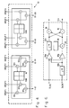
- FIG. 4 illustrates the amplitude weighting and data turning architecture employed in the radiometer 10. The details of construction are clearly shown in the figure and will not be discussed in detail. Generally, however, time invariant weights are stored in a 32x24 bit read only memory 60. A plurality of multipliers 62 provide for weighting of the signals while a plurality of adders 64 implement the data turning.
- the I, Q signals are provided to an amplitude weighting and data turning circuit 32 as 8 parallel groups of signals. The first and fifth groups, second and sixth groups, third and seventh groups and the fourth and eighth groups are weighted and summed. Consequently, four sets of I, Q signals are provided, with each sample being an 8 bit value.
- the amplitude weighting is performed by the multipliers 62 which multiply each of the sampled signals by a predetermined weight, such as Chebyshev weights, or the like. This reduces the sidelobe levels contained in the fanbeams 13.
- a predetermined weight such as Chebyshev weights, or the like.
- the data turning circuit 64 implements a 2:1 data turning of the signals which splits the 256 I, Q input signals into two halves and then sums the two halves together, yielding 128 I, Q samples, thus eliminating alternate lobes from the signals subsequently processed.
- the results of performing a 128 point fast Fourier transform on these 128 samples is equivalent to disposing of every other mainlobe produced by a 256 point fast Fourier transform on the original 256 input signals.
- all samples are of equal amplitude in the time domain and when they are converted to the frequency domain by the fast Fourier transform circuit 34 they have a main lobe and a plurality of side lobes having a 6 dB octave, for example.
- the samples when utilizing the amplitude weighting, the samples have a triangularly shaped amplitude configuration in the time domain and when they are converted to the frequency domain they have a main lobe and a plurality of amplitude reduced side lobes having an 18 dB octave, for example.
- the data turning in essence narrows and increases the amplitude of the main lobe to eliminate mainlobe overlap.
- FIG. 5 shows a detailed diagram of the fast Fourier transform circuit 34 of the beamformer 18.
- This circuit includes two parallel sets of fast Fourier transform circuits 72,73, which comprise butterfly cells, and which implement butterfly computations.
- the outputs of the first butterfly cell of each parallel set is cross coupled to an input of the second butterfly cell of the alternate set.
- the balance of the cells are serially coupled together as shown in the figure. A total of seven butterfly computations are performed in this implementation.
- This fast Fourier transform circuit 34 comprises two sets of seven butterfly cells that are cascaded. The two sets work in parallel with the exception of the signal exchange between the first an second cell 72a, 73b and 73a, 72b.
- the specifics of the butterfly architecture are shown in FIG. 6.
- Each I, Q input signal is coupled to a separate multiplexer 80a, 80b, with one signal passing through a delay 82b prior to the multiplexer 80b.
- the output of the undelayed multiplexer 80a is then delayed in a second delay 82b, while the second output is coupled through a two-input multiplier 84 which couples adjustment factors from a read only memory 86 to the signals processed along that path.
- the output signals of each channel are cross coupled and sum and difference signals are generated from adders 88, 90 as the output signals of the butterfly cell 72a.
- the fast Fourier transform circuit 34 generates 128 I, Q fanbeam values serially over its four output channels.
- the output signals emerge in a bit reversed order, and consequently the fanbeam values are also in reversed order.
- a reordering section is provided just prior to the matched filter, which rearranges the bit reversed outputs back into normal order. This section will be discussed in detail at a later point.
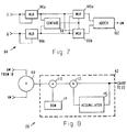
- the vector magnitude circuit 36 of the beamformer 18 is shown in detail in FIG. 7.
- the vector magnitude circuit 36 comprises four parallel cells each of which comprise the cell logic 94 shown in FIG. 7.
- This cell logic 94 shown in FIG. 7 comprises two two-input multiplexers 96a, 96b which accept I and Q input signals and route these signals to a comparison circuit 98.
- the I and Q signals are then applied to a second set of cross coupled multiplexers 100 controlled by the output of the comparison circuit 98 and then applied to an adder 102.
- the adder 102 adds the input signals and provides an output signal comprising the magnitude of the signal being processed.
- the interferometer 20 shown in FIG. 3 includes four parallel channels comprising a multiplier 40 and a low pass filter 42.
- the details of the low pass filter 42 are also shown in FIG. 8.
- the low pass filter 42 comprises a two-input multiplier 110 employed to multiply the signal values by predetermined values stored in a read only memory 114.
- the output of the two input multiplier 110 is coupled to an adder 112 which has an accumulator 116 coupled in a feedback arrangement from its output to its input.
- the accumulator 116 comprises a 32x10 register file.
- the low pass filter 42 stores 32 signals received from the first multiplier 40 before the next 32 signals are added to them.
- the low pass filter 42 is a finite impulse response (FIR) filter implemented by input weighting and accumulation.
- the output signal from the interferometer 20 comprises chirp signals in which the output comprises 32 consecutive chirp waveforms which appear in bursts.
- the matched filter 22 of the radiometer 10 comprises the reordering circuit 46 discussed above along with the matched filter circuit 48.
- the filter is matched to detect the specific chirp waveforms which collapses the processed signals to a series of points which represent the scene. This is accomplished in a conventional manner as is well-known in the art.
- the present invention also contemplates a method of digitally processing an image to provide an image of the scene. This technique provides multiple fanbeams simultaneously and in a cost effective manner. As a result, more integration time, a factor of 128, is available, and hence better sensitivity is provided.
- One method in accordance with the present invention comprises the steps of receiving radiation emitted or reflected from an scene by means of a plurality of substantially parallel antenna arrays. The next step involves converting received radiation into corresponding digitized signals by means of an analog to digital converter coupled to the plurality of antenna arrays. Finally the method provides for processing and digitally synthesizing a large aperture to provide an image corresponding to the scene by means of a digital beamformer and correlating interferometer and matched filter coupled to the analog to digital converter.
- the synthesizing step generally comprises processing the digitized signals by means of individual digital beamformers coupled to two antenna arrays.
- a set of fanbeam signals are generated for each antenna array in order to provide crosstrack imaging of the scene.
- the sets of fanbeam signals provided by each of the beamformers are then processed by means of a digital interferometer to correlate corresponding pairs of fanbeam signals from the two sets of fanbeam signals.
- This process step generates a chirp signal for each pair of fanbeam signals.
- the chirp signals are then processed by means of a matched filter coupled to the digital interferometer to transform each chirp signal into a corresponding image point of the scene, thus providing along track imaging of the scene.
- an aperture synthesized radiometer and method of processing image data which provides for the detection and imaging of soil moisture in the atmosphere and on the earths surface from a remotely located imaging system.
- the present invention is not, however, limited to the detection and display of moisture levels emanating from the earth and atmosphere.
- There are numerous other applications of the present invention including the determination of ocean temperature, and roughness of sea surface, and the like.
Landscapes
- Physics & Mathematics (AREA)
- General Physics & Mathematics (AREA)
- Chemical & Material Sciences (AREA)
- Immunology (AREA)
- Health & Medical Sciences (AREA)
- Analytical Chemistry (AREA)
- Biochemistry (AREA)
- General Health & Medical Sciences (AREA)
- Electromagnetism (AREA)
- Life Sciences & Earth Sciences (AREA)
- Pathology (AREA)
- Engineering & Computer Science (AREA)
- Radar, Positioning & Navigation (AREA)
- Remote Sensing (AREA)
- Radar Systems Or Details Thereof (AREA)
- Radiation Pyrometers (AREA)
Claims (23)
- Radiomètre à synthèse d'ouverture, comprenant :- un ensemble de réseaux d'antenne (12) pratiquement parallèles destinés à recevoir un rayonnement émis ou réfléchi par une scène ;- des moyens de conversion analogique-numérique (16) connectés à l'ensemble de réseaux d'antenne (12) pour convertir un rayonnement reçu en signaux de rayonnement numérisés correspondants ; et- des moyens numériques de formation de faisceau (18) connectés aux moyens de conversion analogique-numérique (16) pour traiter et synthétiser les signaux de rayonnement numérisés, de façon à produire une image correspondant à la scène.
- Radiomètre à synthèse d'ouverture selon la revendication 1, caractérisé en ce que l'ensemble de réseaux d'antenne pratiquement parallèles comprend deux réseaux d'antenne (12a, 12b).
- Radiomètre à synthèse d'ouverture selon la revendication 2, caractérisé en ce que les moyens numériques de formation de faisceau (18) comprennent :- des moyens numériques de formation de faisceau individuels (18) connectés à chacun des réseaux d'antenne (12a, 12b) pour générer un ensemble de signaux de faisceau en éventail pour chaque réseau d'antenne (12a, 12b), de façon à former une image de la scène transversalement au couloir ;- des moyens interférométriques numériques (20) connectés aux moyens de formation de faisceau individuels (8) pour traiter les ensembles de signaux de faisceau en éventail qui sont produits par chacun des moyens de formation de faisceau (18), pour corréler des paires correspondantes de signaux de faisceau en éventail provenant des deux ensembles de signaux de faisceau en éventail, afin de produire un signal impulsionnel modulé en fréquence, ou signal "chirp" pour chaque paire de signaux de faisceau en éventail, de manière à former une image de la scène dans la direction du couloir ; et- des moyens à filtre adapté (22) connectés aux moyens interférométriques numériques (20) pour traiter les signaux impulsionnels modulés en fréquence, de façon à transformer chaque signal impulsionnel modulé en fréquence en un point d'image correspondant dans la scène.
- Radiomètre à synthèse d'ouverture selon la revendication 3, caractérisé en ce que chacun des moyens de formation de faisceau individuels (18) comprend des moyens de transformation de Fourier rapide (34), pour transformer les signaux de rayonnement numérisés de façon à donner les signaux de faisceau en éventail.
- Radiomètre à synthèse d'ouverture selon la revendication 3 ou 4, caractérisé en ce que chacun des moyens numériques de formation de faisceau individuels (18) comprend :- des moyens de pondération d'amplitude (32) pour effectuer une pondération d'amplitude des signaux de rayonnement numérisés, afin de réduire des niveaux de lobes latéraux des signaux de faisceau en éventail ; et- des moyens de rotation de données (32) connectés aux moyens de pondération d'amplitude (32) pour éliminer des lobes principaux alternés dans les signaux de rayonnement numérisés, afin de réduire l'élargissement des lobes principaux des signaux de rayonnement numérisés.
- Radiomètre à synthèse d'ouverture selon la revendication 4 ou 5, caractérisé en ce que chacun des moyens de transformation de Fourier rapide (34) comprend un algorithme de décimation dans le temps qui est exécuté au moyen d'un ensemble de moyens de calcul du type "butterfly" (72), connectés en parallèle et en cascade.
- Radiomètre à synthèse d'ouverture selon l'une quelconque des revendications 4 à 6, caractérisé par des moyens de changement d'ordre (46) connectés aux moyens de transformation de Fourier rapide (34) pour inverser l'ordre des signaux de faisceau en éventail qu'ils fournissent.
- Radiomètre à synthèse d'ouverture selon l'une quelconque des revendications 1 à 7, caractérisé en ce que les moyens de conversion analogique-numérique (16) comprennent :- un ensemble de circuits échantillonneurs-bloqueurs (24) pour échantillonner un ensemble de groupes prédéterminés de signaux du signal de rayonnement reçu ;- un ensemble de multiplexeurs analogiques (26) connectés à des circuits respectifs parmi les circuits échantilllonneurs-bloqueurs (24) pour convertir les groupes de signaux de rayonnement parallèles en groupes de signaux de rayonnement série correspondants ; et- un ensemble de convertisseurs analogique-numérique (28) connectés à des multiplexeurs respectifs de l'ensemble de multiplexeurs analogiques (26), pour convertir les groupes de signaux de rayonnement analogiques série en signaux numériques correspondants.
- Un radiomètre à synthèse d'ouverture selon l'une quelconque des revendications 3 à 8, caractérisé en ce que les moyens interférométriques numériques (20) comprennent :- un ensemble de multiplieurs (40) connectés à des sorties correspondantes de chacun des moyens de formation de faisceau individuels (18), pour multiplier les signaux respectifs qu'ils reçoivent par ces sorties ; et- un ensemble de filtres passe-bas (42) connectés à des multiplieurs respectifs de l'ensemble de multiplieurs (40).
- Radiomètre à synthèse d'ouverture selon la revendication 9, caractérisé en ce que le filtre passe-bas (42) comprend :- un filtre passe-bas à réponse impulsionnelle finie comprenant un second multiplieur (110), comportant une mémoire morte (114) qui mémorise des coefficients de pondération, connecté à un jeu prédéterminé des multiplieurs ;- un additionneur (112) connecté au multiplieur (110) ; et- un accumulateur (116) connecté de la sortie de l'additionneur (112) à l'une de ses entrées.
- Procédé de traitement numérique d'une image, comprenant les étapes suivantes :- on reçoit un rayonnement émis ou réfléchi par une scène, au moyen d'un ensemble de réseaux d'antenne (12) pratiquement parallèles ;- on convertit le rayonnement reçu en signaux de rayonnement numérisés correspondants, à l'aide de moyens de conversion analogique-numérique (16) connectés à l'ensemble de réseaux d'antenne (12) ; et- on traite et on synthétise les signaux de rayonnement numérisés pour produire une image correspondant à la scène, à l'aide de moyens numériques de formation de faisceau (18) qui sont connectés aux moyens de conversion analogique-numérique (16).
- Procédé selon la revendication 11, caractérisé en ce que l'étape de traitement et de synthèse comprend :- la génération d'un jeu de signaux de faisceau en éventail pour chaque réseau d'antenne (12), de façon à former une image de la scène transversalement au couloir ;- le traitement des jeux de signaux de faisceau en éventail pour corréler des paires correspondantes de signaux de faisceau en éventail provenant des deux jeux de signaux de faisceau en éventail ;- la génération d'un signal impulsionnel à fréquence modulée pour chaque paire de signaux de faisceau en éventail, de façon à former une image de la scène le long du couloir ; et- le filtrage adapté des signaux impulsionnels à fréquence modulée pour transformer chaque signal impulsionnel à fréquence modulée en un point d'image correspondant dans la scène.
- Procédé selon la revendication 12, caractérisé en ce que- les signaux de faisceau en éventail sont produits par chacun des moyens de formation de faisceau (18),- l'étape de traitement des jeux de signaux de faisceau en éventail est effectuée à l'aide de moyens interférométriques numériques (20) qui sont connectés aux moyens de formation de faisceau individuels (18),- l'étape de filtrage adapté est effectuée à l'aide de moyens à filtre adapté (22) qui sont connectés aux moyens interférométriques numériques (20).
- Procédé selon l'une quelconque des revendications 11 à 13, caractérisé en ce que l'étape de traitement et de synthèse des signaux de rayonnement numérisés comprend l'étape suivante :- on effectue une transformation de Fourier rapide des signaux de rayonnement numérisés, pour transformer les signaux de rayonnement numérisés de façon à donner les signaux de faisceau en éventail.
- Procédé selon la revendication 14, caractérisé en ce que l'étape de transformation de Fourier rapide est effectuée par des moyens de transformation de Fourier rapide (34).
- Procédé selon l'une quelconque des revendications 11 à 15, caractérisé en ce que l'étape de traitement et de synthèse des signaux de rayonnement numérisés comprend en outre les étapes suivantes :- on effectue une pondération d'amplitude des signaux numérisés pour réduire des niveaux de lobes latéraux des signaux de faisceau en éventail ; et- on effectue une rotation de données sur les signaux à amplitude pondérée, pour éliminer des lobes principaux alternés dans les signaux de rayonnement numérisés, afin de réduire l'élargissement du lobe principal des signaux de rayonnement numérisés.
- Procédé selon l'une quelconque des revendications 11 à 16, caractérisé en ce que l'étape de traitement et de synthèse des signaux de rayonnement numérisés comprend en outre l'étape suivante :- on traite et on synthétise les signaux de rayonnement numérisés au moyen d'un algorithme de décimation dans le temps.
- Procédé selon la revendication 17, caractérisé en ce que l'étape de traitement et de synthèse au moyen d'un algorithme de décimation dans le temps est accomplie à l'aide d'un ensemble de moyens de calcul de type "butterfly" (72) connectés en parallèle et en cascade.
- Procédé selon l'une quelconque des revendications 14 à 18, caractérisé en ce que l'étape de traitement et de synthèse des signaux de rayonnement numérisés comprend en outre l'étape suivante :- on inverse l'ordre des signaux de faisceau en éventail qui sont fournis par l'étape de transformation de Fourier rapide.
- Procédé selon l'une quelconque des revendications 11 à 19, caractérisé en ce que l'étape de conversion comprend :- l'échantillonnage d'un ensemble de groupes prédéterminés de signaux dans le signal de rayonnement reçu ;- la conversion des groupes de signaux de rayonnement parallèles en groupes de signaux de rayonnement série correspondants ; et- la conversion des groupes de signaux de rayonnement analogiques série en signaux numériques correspondants.
- Procédé selon la revendication 20, caractérisé en ce que- l'étape d'échantillonnage est effectuée au moyen d'un ensemble de circuits échantillonneurs-bloqueurs (24);- la première étape de conversion est effectuée au moyen d'un ensemble de multiplexeurs analogiques (26) connectés à des circuits respectifs parmi les circuits échantillonneurs-bloqueurs (24) ; et- la seconde étape de conversion est effectuée au moyen d'un ensemble de convertisseurs analogique-numérique (28) connectés à des multiplexeurs respectifs de l'ensemble de multiplexeurs analogiques (26).
- Procédé selon l'une quelconque des revendications 11 à 21, caractérisé en ce que le traitement des jeux de signaux de faisceau en éventail comprend les étapes suivantes :- on multiplie les signaux respectifs par un ensemble de multiplieurs ; et- on applique un filtrage passe-bas aux signaux multipliés.
- Procédé selon la revendication 22, caractérisé en ce que- les jeux de signaux de faisceau en éventail sont produits par chacun des moyens de formation de faisceau (18) à l'aide de moyens interférométriques numériques (20) ;- l'étape de multiplication est effectuée au moyen d'un ensemble de multiplieurs (40) connectés à des sorties correspondantes de chacun des moyens de formation de faisceau individuels (18) ; et- l'étape de filtrage passe-bas est effectuée au moyen d'un ensemble de filtres passe-bas (42) connectés à des multiplieurs respectifs de l'ensemble de multiplieurs (40).
Applications Claiming Priority (2)
| Application Number | Priority Date | Filing Date | Title |
|---|---|---|---|
| US07/326,935 US5016018A (en) | 1989-03-22 | 1989-03-22 | Aperture synthesized radiometer using digital beamforming techniques |
| US326935 | 1999-06-07 |
Publications (3)
| Publication Number | Publication Date |
|---|---|
| EP0395863A2 EP0395863A2 (fr) | 1990-11-07 |
| EP0395863A3 EP0395863A3 (fr) | 1991-03-13 |
| EP0395863B1 true EP0395863B1 (fr) | 1996-03-06 |
Family
ID=23274405
Family Applications (1)
| Application Number | Title | Priority Date | Filing Date |
|---|---|---|---|
| EP90104989A Expired - Lifetime EP0395863B1 (fr) | 1989-03-22 | 1990-03-16 | Radiomètre à ouverture synthétisée utilisant une technique numérique de concentration du faisceau |
Country Status (5)
| Country | Link |
|---|---|
| US (1) | US5016018A (fr) |
| EP (1) | EP0395863B1 (fr) |
| JP (1) | JPH0782053B2 (fr) |
| CA (1) | CA2009423C (fr) |
| DE (1) | DE69025638T2 (fr) |
Families Citing this family (28)
| Publication number | Priority date | Publication date | Assignee | Title |
|---|---|---|---|---|
| US5142291A (en) * | 1990-08-03 | 1992-08-25 | Hughes Aircraft Company | Passive microwave near-field tomographic imaging system and method |
| US5243351A (en) * | 1992-06-25 | 1993-09-07 | Hughes Aircraft Company | Full aperture image synthesis using rotating strip aperture image measurements |
| US5787049A (en) * | 1995-11-07 | 1998-07-28 | Bates; Kenneth N. | Acoustic wave imaging apparatus and method |
| DE19745370A1 (de) * | 1996-10-16 | 1998-04-23 | Edgar Grassmann | Verfahren und Vorrichtung zur Bestimmung einfallender Empfangsleistung oder -energie wenigstens eines Signales in wenigstens einer vorgebbaren Beobachtungsrichtung sowie Empfangsanlage |
| JPH10256974A (ja) * | 1997-03-14 | 1998-09-25 | Mitsubishi Electric Corp | 移動体衛星通信システム |
| FR2788133B1 (fr) * | 1998-12-30 | 2003-05-02 | Agence Spatiale Europeenne | Systeme radiometrique comprenant une antenne du type a synthese d'ouverture et son application en imagerie hyperfrequence |
| US6614813B1 (en) * | 1999-01-28 | 2003-09-02 | Sandia Corporation | Multiplexed chirp waveform synthesizer |
| US6600446B2 (en) | 2001-06-29 | 2003-07-29 | Lockheed Martin Corporation | Cascadable architecture for digital beamformer |
| AU2002320310A1 (en) * | 2001-07-06 | 2003-01-21 | Wisconsin Alumni Research Foundation | Space-time microwave imaging for cancer detection |
| US6861978B2 (en) * | 2002-04-12 | 2005-03-01 | Lockheed Martin Corporation | Method and system for mutual coherent synthetic aperture radiometry |
| ZA200608087B (en) | 2004-05-28 | 2008-03-26 | Ericsson Telefon Ab L M | A digitizer arrangement |
| WO2005116686A2 (fr) * | 2004-05-28 | 2005-12-08 | Telefonaktiebolaget Lm Ericsson (Publ) | Methode et agencement pour determiner la frequence spatiale d'un signal |
| US8050740B2 (en) * | 2004-09-15 | 2011-11-01 | Wisconsin Alumni Research Foundation | Microwave-based examination using hypothesis testing |
| US7647089B2 (en) * | 2005-01-28 | 2010-01-12 | Wisconsin Alumni Research Foundation | Surface identification using microwave signals for microwave-based detection of cancer |
| US7809427B2 (en) * | 2005-02-11 | 2010-10-05 | Wisconsin Alumni Research Foundation | Time domain inverse scattering techniques for use in microwave imaging |
| US8320474B2 (en) * | 2006-12-06 | 2012-11-27 | Qualcomm Incorporated | Digital frequency hopping in multi-band OFDM |
| US8558734B1 (en) * | 2009-07-22 | 2013-10-15 | Gregory Hubert Piesinger | Three dimensional radar antenna method and apparatus |
| US9136857B2 (en) * | 2012-07-02 | 2015-09-15 | Ifineon Technologies Ag | ADC with sample and hold |
| US9236878B2 (en) | 2014-02-14 | 2016-01-12 | Infineon Technologies Ag | Analog-to-digital conversion |
| CN109541325B (zh) * | 2018-11-27 | 2021-05-11 | 上海航天电子通讯设备研究所 | 一种星载一维综合孔径微波辐射测量系统及测量方法 |
| CN110837074B (zh) * | 2019-11-13 | 2022-05-17 | 电子科技大学 | 一种基于数字波束形成的多同频信源相位干涉仪测向方法 |
| CN111538000B (zh) * | 2020-03-30 | 2023-06-02 | 西南电子技术研究所(中国电子科技集团公司第十研究所) | 均匀圆阵列综合孔径辐射计亮温反演成像方法 |
| CN112834981B (zh) * | 2021-03-15 | 2022-07-15 | 哈尔滨工程大学 | 一种脉冲噪声背景下的零陷阵波达方位估计方法 |
| CN114217140B (zh) * | 2021-09-28 | 2023-03-31 | 北京理工大学 | 一种辐射计信号处理机的数字相关处理方法及装置 |
| CN114035149B (zh) * | 2021-10-25 | 2023-04-25 | 中国电子科技集团公司第二十九研究所 | 一种提升干涉仪测向系统灵敏度的方法 |
| CN113917546B (zh) * | 2021-12-07 | 2024-05-31 | 西安空间无线电技术研究所 | 一种基于馈源合成阵列的星载扫描型推扫辐射计系统 |
| CN115932843B (zh) * | 2022-10-28 | 2025-08-01 | 西安空间无线电技术研究所 | 基于多层感知网络的推扫辐射计数字波束合成方法 |
| CN119805445B (zh) * | 2024-12-27 | 2025-10-03 | 华中科技大学 | 一种基于数字选频的频扫辐射计系统及辐射成像方法 |
Family Cites Families (16)
| Publication number | Priority date | Publication date | Assignee | Title |
|---|---|---|---|---|
| US3942177A (en) * | 1971-07-28 | 1976-03-02 | United Technologies Corporation | Interferometer radar elevation angle measurement apparatus |
| US3953822A (en) * | 1973-10-15 | 1976-04-27 | Rca Corporation | Wave-energy imaging technique |
| US4546355A (en) * | 1982-06-17 | 1985-10-08 | Grumman Aerospace Corporation | Range/azimuth/elevation ship imaging for ordnance control |
| JPS60170774A (ja) * | 1984-02-15 | 1985-09-04 | Natl Space Dev Agency Japan<Nasda> | 合成開口レ−ダ |
| US4724439A (en) * | 1984-05-07 | 1988-02-09 | Hughes Aircraft Company | Microwave radiometer using fanbeam inversion |
| US4780721A (en) * | 1984-07-23 | 1988-10-25 | The Commonwealth Of Australia | Adaptive antenna array |
| US4654666A (en) * | 1984-09-17 | 1987-03-31 | Hughes Aircraft Company | Passive frequency scanning radiometer |
| US4630051A (en) * | 1985-03-01 | 1986-12-16 | Holodyne Ltd., 1986 | Imaging doppler interferometer |
| US4814772A (en) * | 1986-07-02 | 1989-03-21 | Hughes Aircraft Company | Method and apparatus for precisely measuring relative velocity in an interferometric radiometer |
| US4825215A (en) * | 1986-07-03 | 1989-04-25 | Hughes Aircraft Company | Radiometric imager having a frequency-dispersive linear array antenna |
| JPS63165784A (ja) * | 1986-12-27 | 1988-07-09 | Toshiba Corp | 不要波抑圧装置 |
| JPS63186175A (ja) * | 1987-01-28 | 1988-08-01 | Mitsubishi Electric Corp | ホログラフイツクレ−ダ |
| JPS63282678A (ja) * | 1987-05-14 | 1988-11-18 | Mitsubishi Electric Corp | 人工衛星を利用した画像取得方法 |
| CA1234911A (fr) * | 1987-07-16 | 1988-04-05 | Anthony R. Raab | Radiometre a balayage de frequences |
| US4864309A (en) * | 1987-08-18 | 1989-09-05 | Hughes Aircraft Company | Microwave radiometer |
| US4873481A (en) * | 1988-02-16 | 1989-10-10 | Radiometrics Corporation | Microwave radiometer and methods for sensing atmospheric moisture and temperature |
-
1989
- 1989-03-22 US US07/326,935 patent/US5016018A/en not_active Expired - Fee Related
-
1990
- 1990-02-06 CA CA002009423A patent/CA2009423C/fr not_active Expired - Lifetime
- 1990-03-16 DE DE69025638T patent/DE69025638T2/de not_active Expired - Fee Related
- 1990-03-16 EP EP90104989A patent/EP0395863B1/fr not_active Expired - Lifetime
- 1990-03-22 JP JP2073185A patent/JPH0782053B2/ja not_active Expired - Lifetime
Also Published As
| Publication number | Publication date |
|---|---|
| EP0395863A2 (fr) | 1990-11-07 |
| CA2009423C (fr) | 1994-04-19 |
| JPH02280067A (ja) | 1990-11-16 |
| JPH0782053B2 (ja) | 1995-09-06 |
| EP0395863A3 (fr) | 1991-03-13 |
| CA2009423A1 (fr) | 1990-09-22 |
| US5016018A (en) | 1991-05-14 |
| DE69025638T2 (de) | 1996-10-31 |
| DE69025638D1 (de) | 1996-04-11 |
Similar Documents
| Publication | Publication Date | Title |
|---|---|---|
| EP0395863B1 (fr) | Radiomètre à ouverture synthétisée utilisant une technique numérique de concentration du faisceau | |
| US4924229A (en) | Phase correction system for automatic focusing of synthetic aperture radar | |
| US3942150A (en) | Correction of spatial non-uniformities in sonar, radar, and holographic acoustic imaging systems | |
| US5805098A (en) | Method and system for forming image by backprojection | |
| Friedlander et al. | VSAR: A high resolution radar system for ocean imaging | |
| McCorkle et al. | Order N^ 2 log (N) backprojector algorithm for focusing wide-angle wide-bandwidth arbitrary-motion synthetic aperture radar | |
| Schmidt et al. | Multiple source DF signal processing: An experimental system | |
| Cumming et al. | Digital processing of SEASAT SAR data | |
| US4471357A (en) | Pipelined digital SAR azimuth correlator using hybrid FFT/transversal filter | |
| EP0449303B1 (fr) | Dispositif de focalisation automatique mesurant la différence de phase pour la génération d'image dans un système radar à ouverture synthétique | |
| US4136954A (en) | Imaging apparatus including spatial-spectral interferometer | |
| US4990925A (en) | Interferometric radiometer | |
| US4985704A (en) | Processing parameter generator for synthetic aperture radar | |
| US5793703A (en) | Digital time-delay acoustic imaging | |
| US6861978B2 (en) | Method and system for mutual coherent synthetic aperture radiometry | |
| US5191344A (en) | Method for digital generation of sar images and apparatus for carrying out said method | |
| EP0227614A2 (fr) | Dispositif de traitement de signaux pour radar à ouverture synthétique, en particulier adapté au calcul parallèle | |
| Zhao et al. | A novel near field image reconstruction method based on beamforming technique for real-time passive millimeter wave imaging | |
| US4233678A (en) | Serial phase shift beamformer using charge transfer devices | |
| US5610612A (en) | Method for maximum likelihood estimations of bearings | |
| US4870420A (en) | Signal acquisition apparatus and method | |
| US5548561A (en) | Ultrasound image enhancement using beam-nulling | |
| US20020122604A1 (en) | HD fourier transforms for irregularly sampled data | |
| Wu et al. | An introduction to the interim digital SAR processor and the characteristics of the associated Seasat SAR imagery | |
| US4648057A (en) | Robust iterative technique for high-resolution spatial processing and spectral estimation |
Legal Events
| Date | Code | Title | Description |
|---|---|---|---|
| PUAI | Public reference made under article 153(3) epc to a published international application that has entered the european phase |
Free format text: ORIGINAL CODE: 0009012 |
|
| 17P | Request for examination filed |
Effective date: 19900410 |
|
| AK | Designated contracting states |
Kind code of ref document: A2 Designated state(s): DE FR GB IT |
|
| PUAL | Search report despatched |
Free format text: ORIGINAL CODE: 0009013 |
|
| AK | Designated contracting states |
Kind code of ref document: A3 Designated state(s): DE FR GB IT |
|
| 17Q | First examination report despatched |
Effective date: 19931018 |
|
| GRAH | Despatch of communication of intention to grant a patent |
Free format text: ORIGINAL CODE: EPIDOS IGRA |
|
| GRAA | (expected) grant |
Free format text: ORIGINAL CODE: 0009210 |
|
| AK | Designated contracting states |
Kind code of ref document: B1 Designated state(s): DE FR GB IT |
|
| REF | Corresponds to: |
Ref document number: 69025638 Country of ref document: DE Date of ref document: 19960411 |
|
| ET | Fr: translation filed | ||
| ITF | It: translation for a ep patent filed | ||
| PLBE | No opposition filed within time limit |
Free format text: ORIGINAL CODE: 0009261 |
|
| STAA | Information on the status of an ep patent application or granted ep patent |
Free format text: STATUS: NO OPPOSITION FILED WITHIN TIME LIMIT |
|
| 26N | No opposition filed | ||
| REG | Reference to a national code |
Ref country code: GB Ref legal event code: 732E |
|
| REG | Reference to a national code |
Ref country code: FR Ref legal event code: TP Ref country code: FR Ref legal event code: CD Ref country code: FR Ref legal event code: CA |
|
| REG | Reference to a national code |
Ref country code: GB Ref legal event code: IF02 |
|
| PGFP | Annual fee paid to national office [announced via postgrant information from national office to epo] |
Ref country code: DE Payment date: 20030225 Year of fee payment: 14 |
|
| PG25 | Lapsed in a contracting state [announced via postgrant information from national office to epo] |
Ref country code: DE Free format text: LAPSE BECAUSE OF NON-PAYMENT OF DUE FEES Effective date: 20041001 |
|
| PG25 | Lapsed in a contracting state [announced via postgrant information from national office to epo] |
Ref country code: IT Free format text: LAPSE BECAUSE OF NON-PAYMENT OF DUE FEES;WARNING: LAPSES OF ITALIAN PATENTS WITH EFFECTIVE DATE BEFORE 2007 MAY HAVE OCCURRED AT ANY TIME BEFORE 2007. THE CORRECT EFFECTIVE DATE MAY BE DIFFERENT FROM THE ONE RECORDED. Effective date: 20050316 |
|
| PGFP | Annual fee paid to national office [announced via postgrant information from national office to epo] |
Ref country code: GB Payment date: 20090325 Year of fee payment: 20 |
|
| PGFP | Annual fee paid to national office [announced via postgrant information from national office to epo] |
Ref country code: FR Payment date: 20090312 Year of fee payment: 20 |
|
| REG | Reference to a national code |
Ref country code: GB Ref legal event code: PE20 Expiry date: 20100315 |
|
| PG25 | Lapsed in a contracting state [announced via postgrant information from national office to epo] |
Ref country code: GB Free format text: LAPSE BECAUSE OF EXPIRATION OF PROTECTION Effective date: 20100315 |