EP0395921A2 - Dispositif à pinces pour machine à imprimer des feuilles rotative - Google Patents
Dispositif à pinces pour machine à imprimer des feuilles rotative Download PDFInfo
- Publication number
- EP0395921A2 EP0395921A2 EP19900106901 EP90106901A EP0395921A2 EP 0395921 A2 EP0395921 A2 EP 0395921A2 EP 19900106901 EP19900106901 EP 19900106901 EP 90106901 A EP90106901 A EP 90106901A EP 0395921 A2 EP0395921 A2 EP 0395921A2
- Authority
- EP
- European Patent Office
- Prior art keywords
- gripper
- particular according
- gripper device
- sheet
- gap
- Prior art date
- Legal status (The legal status is an assumption and is not a legal conclusion. Google has not performed a legal analysis and makes no representation as to the accuracy of the status listed.)
- Granted
Links
Images



Classifications
-
- B—PERFORMING OPERATIONS; TRANSPORTING
- B41—PRINTING; LINING MACHINES; TYPEWRITERS; STAMPS
- B41F—PRINTING MACHINES OR PRESSES
- B41F21/00—Devices for conveying sheets through printing apparatus or machines
- B41F21/10—Combinations of transfer drums and grippers
- B41F21/104—Gripper details
Definitions
- the invention relates to a gripper device on sheet-fed rotary printing presses according to the preamble of the main claim.
- the object of the present invention is to design a generic gripper device in such a way that, with the same simple design and without additional control engineering effort, no disadvantageous pushing movement is exerted on the sheet even after the gripper is closed.
- a gripper device is created on sheet-fed rotary printing presses in which extremely precise positioning of the sheet is possible because by the fact that even after the gripper has been closed and any kinking of the gripper arm made possible by the articulation point, no thrust movement component directed out of the gripper mouth region against the direction of rotation of the cylinder acts on the arch.
- the articulation point is on the corresponding connecting line or below it - and this then as close as possible - there is no need for any shifting of the gripper finger pointing in the pushing direction after it is placed on the arch with subsequent movement around the articulation point.
- this articulation-dependent movement of the gripper can also be carried out in itself without further disadvantages over a larger movement path that is easier to cushion, in order to achieve, for example, the same advantages with the same means as with gripper arrangements of different designs (e.g. EP-OS 212 365) are achieved in that the surface of the gripper finger placed on the sheet is designed as an inelastic pressure piece, which is, however, supported by an elastic intermediate layer on the gripper finger.
- Even the cushioning effects that can be achieved with such versions can achieve the solution according to the application, but without the inevitable thrust movements that are exerted on the sheet when the gripper is closed, in the case of these previously known concepts.
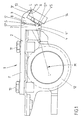
- the gripper device 1 shown has a gripper arm 2, a gripper finger 3 and a V-shaped connection 4 between gripper finger 3 and gripper arm 2.
- the pressure surface 5 of the gripper finger 3 is opposite the sheet gripper support 6.
- the two legs 7, 8 of the V-shaped connection 4 form the gap S.
- the material of the V-apex VS forms the hinge point 14, which lies approximately between the gap lower edge S ′′′ and lower edge 4 'of the V-shaped connection 4.
- the gripper arm 2 is fastened by means of two screws 10, 11 on the gripper housing 12, which can be pivoted about the center of the gripper shaft M (according to FIG. 1).
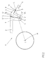
- the pressure surface 5 of the gripper finger 3 lies on one side of the connecting line LL between the gripper shaft center M and the front edge 13 of the gripper finger pressure surface 5.
- the articulation point 14 lies at only a few straight lines the center point M of the rotated gripper shaft causes the V-apex VS forming the joint point 14 with elastic restoring force to narrow the gap S. This occurs after the gripper 1 has been closed.
- the position of the articulation point prevents displacement of the arc in the circumferential direction of the cylinder, arrow x, according to FIG. 2.
- the hinge point 14 itself is not elastic. Rather, two separate V-legs 7, 8 form an articulated socket-like connection engagement 15. With its curvature 16, the leg 8 encloses the lower edge 17 of the leg 7 starting from the gripper arm 2 with an angle ⁇ of approximately 120 °.
- the restoring force is generated by an elastic cushion 20, which is held in this embodiment in dovetail guides 18, 19 in the gap limiting walls S 'and S ⁇ of the legs 7, 8. This can also be glued or sprayed on.
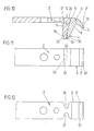
- the lower edge 17 of the V-leg 7 has, as can be seen in FIG. 4, a convex shape 21.
- This shape 21 has, inter alia, the Advantage that it automatically creates a parallelism when the gripper finger pressure surface 5 and the sheet gripper support 6 are not exactly parallel, since the leg 8 adjusts itself in parallel assignment to the sheet gripper support 6.
- the cohesion of parts 7 and 8 is such. B. sufficiently given only by the dovetail connection.
- V-leg 8 can, as can be seen in the above three embodiments, have a spherical shape of the gap boundary wall S '.
- This shape 25 has i.a. the advantage that the inserts generating the elastic restoring forces can be of different types, they can be designed both as an elastic cushion 26, as a compression spring 27 or as a leaf spring 28.
- the crowning of the contact surface increases it with the same gap, which e.g. can be advantageous for compression, any adhesive attachment, etc.
- the articulated point 14 designed as a spring section 29 of FIGS. 8 and 9 is at right angles to the gap delimitation walls S 'and S ⁇ which accommodate the elastic restoring forces producing elastic cushion 20 (e.g. hard rubber, plastic).
- the spring section 29 is placed against the V-legs 7, 8 from below. 9, the spring section 29 forms the connection between the V-legs 7, 8, in that leaf springs are inserted into grooves 30, 31 in the lower quarter of the V-section 4.
- the pad 20 is held in an elongated hole, a bore 33 or more thereof. These are arranged in the lower part 34 of the V-section 4.
- the elastic pad 20 has on its underside a cone-shaped configuration 35 which has approximately the diameter of the bore 33.
- the upper part of the cushion 20 is approximately wedge-shaped and adapted to the gap limiting walls S 'and S ⁇ .
- the lower part 34 of the V-section 4 here forms the articulation point 14. The weakening takes place through the hole 33 in order to increase the articulation ability.
- V-apex VS can also form a narrowing from the outside due to the lateral constriction 36, 37.
- the gripper arm 2 is formed by a V-shaped extension 42 of the same cross section.
- the V-apex VS lies approximately in the middle of the connecting line L-L as a reversal point in the course of the gripper arm 2.
- V-apex VS or the joint 14 lies below the line L-L.
- the V-legs dip approximately radially into a corresponding cylinder pit.
Landscapes
- Supply, Installation And Extraction Of Printed Sheets Or Plates (AREA)
- Feeding Of Articles By Means Other Than Belts Or Rollers (AREA)
Applications Claiming Priority (2)
| Application Number | Priority Date | Filing Date | Title |
|---|---|---|---|
| DE3914646 | 1989-05-03 | ||
| DE3914646A DE3914646A1 (de) | 1989-05-03 | 1989-05-03 | Greifereinrichtung an bogenrotationsdruckmaschinen |
Publications (3)
| Publication Number | Publication Date |
|---|---|
| EP0395921A2 true EP0395921A2 (fr) | 1990-11-07 |
| EP0395921A3 EP0395921A3 (fr) | 1991-03-27 |
| EP0395921B1 EP0395921B1 (fr) | 1994-07-13 |
Family
ID=6380033
Family Applications (1)
| Application Number | Title | Priority Date | Filing Date |
|---|---|---|---|
| EP90106901A Expired - Lifetime EP0395921B1 (fr) | 1989-05-03 | 1990-04-10 | Dispositif à pinces pour machine à imprimer des feuilles rotative |
Country Status (4)
| Country | Link |
|---|---|
| US (1) | US5048815A (fr) |
| EP (1) | EP0395921B1 (fr) |
| JP (1) | JPH02303839A (fr) |
| DE (2) | DE3914646A1 (fr) |
Families Citing this family (7)
| Publication number | Priority date | Publication date | Assignee | Title |
|---|---|---|---|---|
| DE3921474A1 (de) * | 1989-06-30 | 1991-01-10 | Heidelberger Druckmasch Ag | Bogengreifereinrichtung fuer bogenrotationsdruckmaschinen |
| DE4101987A1 (de) * | 1991-01-24 | 1992-07-30 | Roland Man Druckmasch | Bogengreifereinrichtung an bogen-rotationsdruckmaschinen |
| DE4127713C2 (de) * | 1991-08-22 | 1996-03-21 | Koenig & Bauer Albert Ag | Greifer für Bogenrotationsdruckmaschinen |
| DE19816512B4 (de) * | 1997-08-18 | 2008-08-28 | Heidelberger Druckmaschinen Ag | Bogengreifer in einer Bogenrotationsdruckmaschine |
| US6213459B1 (en) * | 1998-07-10 | 2001-04-10 | Heidelberger Druckmaschinen Ag | Signature gripper and delivery device |
| CN1757511B (zh) * | 2004-09-08 | 2010-08-04 | 海德堡印刷机械股份公司 | 单张纸承印材料叼纸牙 |
| DE102008056239A1 (de) * | 2007-11-29 | 2009-06-04 | Heidelberger Druckmaschinen Ag | Greifer zum Fördern eines Bogens durch eine drucktechnische Maschine |
Family Cites Families (10)
| Publication number | Priority date | Publication date | Assignee | Title |
|---|---|---|---|---|
| US1519944A (en) * | 1922-05-01 | 1924-12-16 | August W Warsen | Gripper for printing presses and paper-using machines |
| DE1908181A1 (de) * | 1969-02-19 | 1970-11-05 | Roland Offsetmaschf | Klemmgreifer fuer Bogenrotationsdruckmaschinen |
| DE2337210A1 (de) * | 1973-07-21 | 1975-02-06 | Maschf Augsburg Nuernberg Ag | Klemmgreifer fuer bogenverarbeitende, intermittierend foerdernde maschinen, insbesondere druck- und stanzmaschinen |
| ES230780Y (es) * | 1977-08-26 | 1978-07-01 | Conjunto de pinza y abrazadera para el transporte de laminasen maquinas litograficas. | |
| US4634107A (en) * | 1984-09-07 | 1987-01-06 | Bell & Howell Company | Gripper arm and method of operation |
| DE3529599A1 (de) * | 1985-08-19 | 1987-02-26 | Roland Man Druckmasch | Bogengreifereinrichtung fuer bogenrotationsdruckmaschinen |
| CH667860A5 (en) * | 1985-10-24 | 1988-11-15 | Ferag Ag | Selected grip-opening mechanism on conveyor - delivers opening members to grips to be opened along closed track |
| US4728097A (en) * | 1986-02-05 | 1988-03-01 | Bell & Howell Company | Adjustable gripper arm |
| DD250501A1 (de) * | 1986-06-30 | 1987-10-14 | Polygraph Leipzig | Bogengreifereinrichtung |
| DE3623405A1 (de) * | 1986-07-11 | 1988-02-04 | Miller Johannisberg Druckmasch | Bogengreifer fuer bogenverarbeitende maschinen |
-
1989
- 1989-05-03 DE DE3914646A patent/DE3914646A1/de not_active Withdrawn
-
1990
- 1990-04-10 DE DE59006396T patent/DE59006396D1/de not_active Expired - Fee Related
- 1990-04-10 EP EP90106901A patent/EP0395921B1/fr not_active Expired - Lifetime
- 1990-05-01 JP JP2111899A patent/JPH02303839A/ja active Pending
- 1990-05-03 US US07/518,209 patent/US5048815A/en not_active Expired - Lifetime
Also Published As
| Publication number | Publication date |
|---|---|
| JPH02303839A (ja) | 1990-12-17 |
| DE3914646A1 (de) | 1990-11-08 |
| EP0395921B1 (fr) | 1994-07-13 |
| DE59006396D1 (de) | 1994-08-18 |
| US5048815A (en) | 1991-09-17 |
| EP0395921A3 (fr) | 1991-03-27 |
Similar Documents
| Publication | Publication Date | Title |
|---|---|---|
| DE29614023U1 (de) | Computertaste | |
| DE10026169C2 (de) | Verwendung eines elastischen Konstruktionselements als Torsionsfeder | |
| DE2517234A1 (de) | Flexibles bauteil fuer ein brillengestell | |
| EP0395921B1 (fr) | Dispositif à pinces pour machine à imprimer des feuilles rotative | |
| EP0523435A1 (fr) | Coupeuse transversale d'une plieuse pour des rotatives à bobines | |
| EP0476244B1 (fr) | Doigt de pince d'un arbre à pinces d'une machine d'impression alimentée en feuilles | |
| DE102016101466B4 (de) | Fahrradbremse | |
| DE2718109A1 (de) | Drosselventilsteuerung | |
| DE4415788A1 (de) | Schwenkflügelweiche | |
| DE1922749B2 (de) | Vorrichtung zur Befestigung einer Druckplatte auf dem Formzylinder einer Druckmaschine | |
| DE3217672A1 (de) | Montagekopf fuer handhabungsgeraete | |
| DE4201959A1 (de) | Schraubendruckfederanordnung | |
| DE29903503U1 (de) | Steller für Deckel | |
| DE2841337C2 (fr) | ||
| DE2635631C3 (de) | Vorrichtung zur schwenkbaren Auflage eines Rahmens, insbesondere fur Führungswalzen für dünne Materialbahnen, der gegenüber einer Bezugsebene verdrehbar ist | |
| DE69200699T2 (de) | Förderer. | |
| DE2253729B2 (de) | Breithalterzylinder | |
| DE202012008922U1 (de) | Führungselement für eine Schutzabdeckung | |
| DE1673435A1 (de) | Drehzahlregeleinrichtung,beispielsweise fuer eine Brennstoffpumpe | |
| DE4101987C2 (fr) | ||
| DE2105134C3 (de) | Rotorarm für eine Silo-Austragvorrichtung | |
| DE2736219C2 (de) | Verschluß an einem Leuchtengehäuse mit zwei voneinander lösbaren Gehäuseteilen | |
| AT390224B (de) | Vorrichtung zum biegen und pressen von geschichteten holzlagen | |
| AT395552B (de) | Kombinations-haarschneideschere | |
| EP0576047A2 (fr) | Appareil de couplage haute tension |
Legal Events
| Date | Code | Title | Description |
|---|---|---|---|
| PUAI | Public reference made under article 153(3) epc to a published international application that has entered the european phase |
Free format text: ORIGINAL CODE: 0009012 |
|
| 17P | Request for examination filed |
Effective date: 19900410 |
|
| AK | Designated contracting states |
Kind code of ref document: A2 Designated state(s): DE ES FR GB IT SE |
|
| PUAL | Search report despatched |
Free format text: ORIGINAL CODE: 0009013 |
|
| AK | Designated contracting states |
Kind code of ref document: A3 Designated state(s): DE ES FR GB IT SE |
|
| RIN1 | Information on inventor provided before grant (corrected) |
Inventor name: HILTWEIN, HANS-PETER, DIPL.-ING. Inventor name: HILTWEIN HANS-PETER |
|
| K1C1 | Correction of patent application (title page) published |
Effective date: 19901107 |
|
| 17Q | First examination report despatched |
Effective date: 19930112 |
|
| RBV | Designated contracting states (corrected) |
Designated state(s): DE GB |
|
| GRAA | (expected) grant |
Free format text: ORIGINAL CODE: 0009210 |
|
| AK | Designated contracting states |
Kind code of ref document: B1 Designated state(s): DE GB |
|
| REF | Corresponds to: |
Ref document number: 59006396 Country of ref document: DE Date of ref document: 19940818 |
|
| GBT | Gb: translation of ep patent filed (gb section 77(6)(a)/1977) |
Effective date: 19940926 |
|
| PGFP | Annual fee paid to national office [announced via postgrant information from national office to epo] |
Ref country code: GB Payment date: 19950320 Year of fee payment: 6 |
|
| PLBE | No opposition filed within time limit |
Free format text: ORIGINAL CODE: 0009261 |
|
| STAA | Information on the status of an ep patent application or granted ep patent |
Free format text: STATUS: NO OPPOSITION FILED WITHIN TIME LIMIT |
|
| 26N | No opposition filed | ||
| PG25 | Lapsed in a contracting state [announced via postgrant information from national office to epo] |
Ref country code: GB Effective date: 19960410 |
|
| GBPC | Gb: european patent ceased through non-payment of renewal fee |
Effective date: 19960410 |
|
| PGFP | Annual fee paid to national office [announced via postgrant information from national office to epo] |
Ref country code: DE Payment date: 20080423 Year of fee payment: 19 |
|
| PG25 | Lapsed in a contracting state [announced via postgrant information from national office to epo] |
Ref country code: DE Free format text: LAPSE BECAUSE OF NON-PAYMENT OF DUE FEES Effective date: 20091103 |