EP0395936A1 - Dispositif de mesure de position avec plusieurs points de capteur - Google Patents
Dispositif de mesure de position avec plusieurs points de capteur Download PDFInfo
- Publication number
- EP0395936A1 EP0395936A1 EP90107305A EP90107305A EP0395936A1 EP 0395936 A1 EP0395936 A1 EP 0395936A1 EP 90107305 A EP90107305 A EP 90107305A EP 90107305 A EP90107305 A EP 90107305A EP 0395936 A1 EP0395936 A1 EP 0395936A1
- Authority
- EP
- European Patent Office
- Prior art keywords
- scanning
- main scanning
- signal
- unit
- measuring device
- Prior art date
- Legal status (The legal status is an assumption and is not a legal conclusion. Google has not performed a legal analysis and makes no representation as to the accuracy of the status listed.)
- Granted
Links
- 239000000523 sample Substances 0.000 title 1
- 238000012937 correction Methods 0.000 claims description 6
- 230000015572 biosynthetic process Effects 0.000 claims 1
- 230000000737 periodic effect Effects 0.000 description 33
- 230000010363 phase shift Effects 0.000 description 10
- 238000012545 processing Methods 0.000 description 8
- 238000011156 evaluation Methods 0.000 description 4
- 230000001133 acceleration Effects 0.000 description 3
- 230000035939 shock Effects 0.000 description 3
- 230000002411 adverse Effects 0.000 description 1
- 230000008033 biological extinction Effects 0.000 description 1
- 230000003139 buffering effect Effects 0.000 description 1
- 238000011161 development Methods 0.000 description 1
- 230000018109 developmental process Effects 0.000 description 1
- 230000000694 effects Effects 0.000 description 1
- 230000001939 inductive effect Effects 0.000 description 1
- 238000003754 machining Methods 0.000 description 1
- 238000005259 measurement Methods 0.000 description 1
- 238000012544 monitoring process Methods 0.000 description 1
- 238000005070 sampling Methods 0.000 description 1
- 238000012360 testing method Methods 0.000 description 1
Images

Classifications
-
- G—PHYSICS
- G01—MEASURING; TESTING
- G01D—MEASURING NOT SPECIALLY ADAPTED FOR A SPECIFIC VARIABLE; ARRANGEMENTS FOR MEASURING TWO OR MORE VARIABLES NOT COVERED IN A SINGLE OTHER SUBCLASS; TARIFF METERING APPARATUS; MEASURING OR TESTING NOT OTHERWISE PROVIDED FOR
- G01D5/00—Mechanical means for transferring the output of a sensing member; Means for converting the output of a sensing member to another variable where the form or nature of the sensing member does not constrain the means for converting; Transducers not specially adapted for a specific variable
- G01D5/12—Mechanical means for transferring the output of a sensing member; Means for converting the output of a sensing member to another variable where the form or nature of the sensing member does not constrain the means for converting; Transducers not specially adapted for a specific variable using electric or magnetic means
- G01D5/244—Mechanical means for transferring the output of a sensing member; Means for converting the output of a sensing member to another variable where the form or nature of the sensing member does not constrain the means for converting; Transducers not specially adapted for a specific variable using electric or magnetic means influencing characteristics of pulses or pulse trains; generating pulses or pulse trains
- G01D5/24471—Error correction
- G01D5/24476—Signal processing
-
- G—PHYSICS
- G01—MEASURING; TESTING
- G01D—MEASURING NOT SPECIALLY ADAPTED FOR A SPECIFIC VARIABLE; ARRANGEMENTS FOR MEASURING TWO OR MORE VARIABLES NOT COVERED IN A SINGLE OTHER SUBCLASS; TARIFF METERING APPARATUS; MEASURING OR TESTING NOT OTHERWISE PROVIDED FOR
- G01D5/00—Mechanical means for transferring the output of a sensing member; Means for converting the output of a sensing member to another variable where the form or nature of the sensing member does not constrain the means for converting; Transducers not specially adapted for a specific variable
- G01D5/12—Mechanical means for transferring the output of a sensing member; Means for converting the output of a sensing member to another variable where the form or nature of the sensing member does not constrain the means for converting; Transducers not specially adapted for a specific variable using electric or magnetic means
- G01D5/244—Mechanical means for transferring the output of a sensing member; Means for converting the output of a sensing member to another variable where the form or nature of the sensing member does not constrain the means for converting; Transducers not specially adapted for a specific variable using electric or magnetic means influencing characteristics of pulses or pulse trains; generating pulses or pulse trains
- G01D5/245—Mechanical means for transferring the output of a sensing member; Means for converting the output of a sensing member to another variable where the form or nature of the sensing member does not constrain the means for converting; Transducers not specially adapted for a specific variable using electric or magnetic means influencing characteristics of pulses or pulse trains; generating pulses or pulse trains using a variable number of pulses in a train
- G01D5/2451—Incremental encoders
Definitions
- the invention relates to a position measuring device with a plurality of scanning points according to the preamble of claim 1.
- Such a position measuring device is used in particular in machine tools for measuring the relative position of a tool with respect to a workpiece to be machined, and in coordinate measuring machines for determining the position and / or dimensions of test objects.
- Position measuring devices are understood to mean absolute or incremental length or angle measuring devices, in which the division of a graduation carrier is scanned by a scanning unit to generate periodic scanning signals, from which measured values for the relative position of the two mutually displaceable objects, for example the tool and the like, are measured in an evaluation device Workpiece or the two associated machine parts of the processing machine can be obtained.
- the graduation of the graduation carrier can, however, have partial graduation inaccuracies.
- graduation marks of the graduation may also be missing at the joints between the sections.
- eccentricities can also occur between the angular division and the axis of rotation of the two objects to be measured.
- these aforementioned interferences can have negative effects on the required measuring accuracy.
- a length measuring device in which the division of a graduation carrier is scanned by two scanning units spaced apart in the measuring direction.
- the periodic scanning signals obtained from the two scanning units are superimposed in an analog form on top of each other, so that there is a higher measuring accuracy, since the two scanning units scan a total of a larger area of the division of the graduation carrier than with only one scanning unit provided; possible inaccuracies of division have practically no influence on the measuring accuracy by this measure.
- US Pat. No. 4,580,047 describes an angle measuring device with two scanning units at two diametrically opposite scanning points for eliminating eccentricity errors and for monitoring the phase position of the periodic scanning signals.
- DE-OS 18 11 961 also discloses an angle measuring device with two scanning units at two diametrically opposite scanning points, the periodic scanning signals of which are additively superimposed on one another in analog form, so that in addition to the ineffectiveness of possible pitch inaccuracies of the graduated disk, eccentricity errors in the mounting of the graduated disk are also eliminated.
- the two periodic scanning signals of the same pha obtained, for example, during the double scanning of the angular division of an angle measuring device by means of the two scanning units at the two scanning points
- the practically always existing eccentricity causes a mutual phase shift of the two periodic scanning signals, which can be permitted to a certain extent without adversely affecting the measuring accuracy; the still permissible eccentricity should therefore not exceed one tenth of the lattice constant (period length) of the angular division. If this limit value is exceeded, there is a risk that the analog sum signal of the two periodic scanning signals will become too small.
- the periodic scanning signal of the first scanning unit at the first scanning location leads 90 ° in phase and the periodic scanning signal of the second scanning unit at the second scanning location 90 ° behind, so that the two periodic scanning signals have a mutual phase difference of 180 °, which leads to an extinction of their sum signal, so that no measured value can be formed.
- the invention is based on the object of specifying a position measuring device with a plurality of scanning points, in which external interference influences have no influence on the measuring accuracy.
- the advantages achieved by the invention consist in particular in that, by the additional evaluation of at least one scanning signal of a scanning unit in the event of faults in which the at least one superimposed signal can no longer be evaluated, all scanned division periods of the incremental division are nevertheless detected.
- a first angle measuring device is schematically shown, in which a graduated disc TT is attached with an incremental angular pitch WT to a shaft W, which with a rotatable object, not shown, for example with a Spindle of a machine table of a processing machine is connected.
- a main scanning unit HA and three secondary scanning units NA1, NA2, NA3 are connected to a stationary object, also not shown, for example with a bed of the processing machine; the main scanning unit HA and the first sub-scanning unit NA1 as well as the second sub-scanning unit NA2 and the third sub-scanning unit NA3 scan the angular division WT of the indexing disk TT at two diametrically opposite scanning points, the main scanning point HT and the three sub-scanning points NT1, NT2, NT3.
- the main scanning unit HA and the first sub-scanning unit NA1 are each offset by 90 ° from the second sub-scanning unit NA2 and the third sub-scanning unit NA3.
- the main scanning unit HA When the indexing disk TT rotates with respect to the main scanning unit HA and the three sub-scanning units NA1, NA2, NA3, the main scanning unit HA generates two periodic main scanning signals HS1, HS2 with a mutual phase offset of 90 ° and the three sub-scanning units NA1, NA2, NA3 each have two periodic sub-scanning signals NS1 , NS2, NS3, NS4, NS5, NS6 with the same mutual phase offset of 90 °; this phase shift of 90 ° serves in a known manner to discriminate the measuring direction X (direction of rotation of the indexing disk TT).
- the first main scanning signal HS1 of the main scanning unit HA and the three first sub-scanning signals NS1, NS3, NS5 of the three sub-scanning units NA1, NA2, NA3 thus have the phase positions 0 ° and the second main scanning signal HS2 and the three second sub-scanning signals NS2, NS4, NS6 the phase positions 90 ° if there is no eccentricity e.
- the center M of the index plate TT and thus the angular pitch WT may now have the eccentricity e with respect to the axis of rotation D of the shaft W.
- This eccentricity e can be caused by an imperfect centering of the center M of the indexing plate TT or the angular pitch WT with respect to the axis of rotation D of the shaft W, by bearing errors of the shaft W or by accelerations due to shocks or vibrations of the processing machine that momentarily the indexing plate TT remove from their central position.
- This eccentricity e results in a phase shift 2 ⁇ which can be understood in such a way that the two periodic main scanning signals HS1, HS2 of the main scanning unit HA lead, for example, by the phase shift + ⁇ and the two periodic secondary scanning signals NS1, NS2 of the diametrically opposite first secondary scanning unit NA1 by that Lag phase - ⁇ lag, based in each case on the required phase positions 0 ° and 90 ° with no eccentricity e;
- the two analog periodic main scanning signals HS1, HS2 on a first channel K1 are converted into two main square wave signals HR1, HR2 in an evaluation device AW by means of two trigger stages T1, T2 and an up / down counter Z for counting the division periods of the angular division WT of the indexing disk TT fed.
- the first analog periodic main scanning signal HS1 of the main scanning unit HA and the first three analog periodic secondary scanning signals NS1, NS3, NS5 of the three Auxiliary scanning units NA1 - NA3 - which are jointly assigned to the phase angle 0 ° - are superimposed on one another in an analog manner and fed as the first averaged signal GS1 on a second channel K2 to a subdivision unit UT.
- the second analog periodic main scanning signal HS2 of the main scanning unit HA and the three second analog periodic secondary scanning signals NS2, NS4, NS6 of the three secondary scanning units NA1 - NA3 - which are jointly assigned to the phase position 90 ° - are superimposed on one another in an analog manner and as the second averaged signal GS2 on the second channel K2 of the subdivision unit UT.
- the coded count value ZW of the up / down counter Z and the coded division value UW of the division unit UT are fed to a code connection logic S which contains variants of the coded division value UW and the coded count value ZW for generating the measured values MW for the relative position of the two objects; this code connection logic S can consist of a read-only memory.
- a code connection logic S which contains variants of the coded division value UW and the coded count value ZW for generating the measured values MW for the relative position of the two objects; this code connection logic S can consist of a read-only memory.
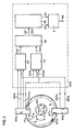
- FIG. 2 schematically shows a second angle measuring device, in which a graduated disk TTa with an incremental angular pitch WTa is attached to a shaft Wa, which is connected to a rotatable object, not shown, for example with a spindle of a machine table of a processing machine.
- a main scanning unit HAa and a secondary scanning unit NAa are connected to a stationary object, also not shown, for example with a bed of the processing machine; the main scan Unit HAa and the secondary scanning unit NAa scan the angular division WTa of the indexing disk TTa at two diametrically opposite scanning points, the main scanning point HTa and the secondary scanning point NTa.
- the main scanning unit HAa When the indexing disk TTa rotates with respect to the main scanning unit HAa and the secondary scanning unit NAa, the main scanning unit HAa generates two periodic main scanning signals HS1a, HS2a with a mutual phase offset of 90 ° and the secondary scanning unit NAa produces two periodic secondary scanning signals NS1a, NS2a with the same mutual phase offset of 90 °; this phase shift of 90 ° is used in a known manner to discriminate the measuring direction X (direction of rotation of the index plate TTa).
- the first main scanning signal HS1a of the main scanning unit HAa and the first sub-scanning signal NS1a of the sub-scanning unit NAa thus have the phase positions 0 ° and the second main scanning signal HS2a and the second sub-scanning signal NS2a have the phase positions 90 ° if there is no eccentricity e.
- the center point Ma of the indexing plate TTa and thus the angular division WTa may now have the eccentricity e with respect to the axis of rotation Da of the shaft Wa.
- This eccentricity e can be caused by imperfect centering of the center point Ma of the indexing plate TTa or the angular division WTa with respect to the axis of rotation.
- the shaft Wa can be caused by bearing errors of the shaft Wa or by accelerations as a result of shocks or vibrations of the processing machine, which currently remove the indexing disk TTa from its central position.
- This eccentricity e causes a phase shift 2 ⁇ which can be understood to mean that the two periodic main scanning signals HS1a, HS2a of the main scanning unit HAa, for example, lead by the phase shift + ⁇ and lag the two periodic sub-scanning signals NS1a, NS2a of the diametrically opposite sub-scanning unit NAa by the phase shift - ⁇ , based in each case on the required phase positions 0 ° with no eccentricity e.
- the two analog periodic main scanning signals HS1a, HS2a are divided into eight on a first channel K1a in a first interpolator P1 in an evaluation device AWa.
- the first analog periodic main scanning signal HS1a of the main scanning unit HAa and the first analog periodic secondary scanning signal NS1a of the secondary scanning unit NAa - which are jointly assigned to the phase position 0 ° - are analogously superimposed on one another and as the first averaged signal GS1a on a second channel K2a a second interpolator P2 fed;
- the second analog periodic main scanning signal HS2a of the main scanning unit HAa and the second analog periodic secondary scanning signal NS2a of the secondary scanning unit NAa - which are jointly assigned to the phase position 90 ° - are superimposed on one another in an analog manner and fed as a second averaged signal GS2a on the second channel K2a to the second interpolator P2 .
- These two averaged signals GS1a, GS2a are divided, for example, 50-fold in the second interpolator P2; the minimum interpolation of the two interpolators P1, P2 must be 8 times.
- the interpolation values of the two interpolators P1, P2 are fed as parallel code values CW1, CW2 to a correction module KB, which contains the octant information of the code values CW1 of the two main ones Taster signals HS1a, HS2a with the octant information of the corresponding code values CW2 of the two averaged signals GS1a, GS2a compared using a stored correction table.
- the code values CW1 of the two main scanning signals HS1a, HS2a and the code values CW2 of the two averaged signals GS1a, GS2a If there is a match or a maximum difference of one octant between the code values CW1 of the two main scanning signals HS1a, HS2a and the code values CW2 of the two averaged signals GS1a, GS2a, the code values CW2 of the two averaged signals GS1a, GS2a and, in all other cases, the code values CW1 of the two main scanning signals HS1a, HS2a forwarded to a known tracking circuit NS.
- This tracking circuit NS generates two periodic square-wave signals R1, R2 with a mutual phase shift of 90 ° by buffering the code values CW1 of the two main scanning signals HS1a, HS2a and the code values CW2 of the two averaged signals GS1a, GS2a in a temporally fixed raster and from them Comparison between the new code values CW1 and CW2 and the preceding code values CW1 and CW2 determines the measuring direction and the number of counting edges to be output. Correct operation is provided as long as the difference between the new code values CW1 or CW2 and the previous code values CW1 or CW2 does not exceed half a subdivision period.
- the measured values MW for the relative position of the two objects are obtained in a known manner from the two square-wave signals R1, R2 in a counter Z.
- the invention can be used successfully both with angle measuring devices and with length measuring devices which are based on the photoelectric, magnetic, inductive or capacitive measuring principle.
Landscapes
- Physics & Mathematics (AREA)
- General Physics & Mathematics (AREA)
- Engineering & Computer Science (AREA)
- Signal Processing (AREA)
- Transmission And Conversion Of Sensor Element Output (AREA)
- Vehicle Body Suspensions (AREA)
- Length Measuring Devices With Unspecified Measuring Means (AREA)
- Optical Transform (AREA)
Priority Applications (1)
| Application Number | Priority Date | Filing Date | Title |
|---|---|---|---|
| AT90107305T ATE83856T1 (de) | 1989-05-03 | 1990-04-18 | Positionsmesseinrichtung mit mehreren abtastsstellen. |
Applications Claiming Priority (2)
| Application Number | Priority Date | Filing Date | Title |
|---|---|---|---|
| DE3914557A DE3914557A1 (de) | 1989-05-03 | 1989-05-03 | Positionsmesseinrichtung mit mehreren abtaststellen |
| DE3914557 | 1989-05-03 |
Publications (2)
| Publication Number | Publication Date |
|---|---|
| EP0395936A1 true EP0395936A1 (fr) | 1990-11-07 |
| EP0395936B1 EP0395936B1 (fr) | 1992-12-23 |
Family
ID=6379973
Family Applications (1)
| Application Number | Title | Priority Date | Filing Date |
|---|---|---|---|
| EP90107305A Expired - Lifetime EP0395936B1 (fr) | 1989-05-03 | 1990-04-18 | Dispositif de mesure de position avec plusieurs points de capteur |
Country Status (3)
| Country | Link |
|---|---|
| EP (1) | EP0395936B1 (fr) |
| AT (1) | ATE83856T1 (fr) |
| DE (2) | DE3914557A1 (fr) |
Cited By (8)
| Publication number | Priority date | Publication date | Assignee | Title |
|---|---|---|---|---|
| EP1248078A2 (fr) * | 2001-04-03 | 2002-10-09 | Kabushiki Kaisha Topcon | Codeur optique absolu |
| EP1489387A1 (fr) * | 2003-06-19 | 2004-12-22 | Codechamp S.A. | Procédé d'interpolation angulaire réalisé pour codeur optique haute résolution et le codeur optique |
| EP1632753A3 (fr) * | 2004-09-06 | 2007-02-14 | Lenord, Bauer & Co. GmbH | Méthode de calibration électronique de tolérances mechaniques de construction de capteurs de position |
| EP1923670A1 (fr) * | 2006-11-17 | 2008-05-21 | AMO Automatisierung Messtechnik Optik GmbH | Dispositif de mesure de position |
| EP1959241A3 (fr) * | 2007-02-15 | 2014-01-22 | Canon Kabushiki Kaisha | Appareil de détection d'angle de rotation |
| CN105928547A (zh) * | 2014-05-06 | 2016-09-07 | 盛铂科技(上海)有限公司 | 一种旋转编码器二相信号处理电路及其信号处理方法 |
| EP2278277A3 (fr) * | 2009-07-10 | 2016-12-28 | Mitutoyo Corporation | Procédé de calcul des erreurs d'un dispositif de détection d'angle |
| CN107824813A (zh) * | 2017-11-06 | 2018-03-23 | 同济大学 | 基于两步在线检测和补偿技术的自由曲面加工方法和装置 |
Families Citing this family (6)
| Publication number | Priority date | Publication date | Assignee | Title |
|---|---|---|---|---|
| DE4328525A1 (de) * | 1993-08-25 | 1995-04-06 | Mikroelektronik Und Technologi | Längen- oder Winkelmeßeinrichtung |
| DE4402401C2 (de) * | 1994-01-27 | 1997-05-22 | Heidenhain Gmbh Dr Johannes | Winkelmeßeinrichtung mit mehreren Abtaststellen |
| US5774074A (en) * | 1997-01-21 | 1998-06-30 | Hewlett-Packard Company | Multi-track position encoder system |
| DE59805985D1 (de) | 1997-06-28 | 2002-11-21 | Kostal Leopold Gmbh & Co Kg | Verfahren zum bestimmen der absoluten winkelstellung des lenkrades eines kraftfahrzeuges sowie optoelektronischer lenkwinkelsensor |
| DE19920596C2 (de) * | 1999-05-05 | 2003-10-30 | Maerzhaeuser Senso Tech Gmbh | Verfahren zum Messen der Relativlage zweier Objekte |
| DE102005042616B4 (de) * | 2005-09-07 | 2010-07-08 | Bourns, Inc., Riverside | Drehstellungssensor |
Citations (4)
| Publication number | Priority date | Publication date | Assignee | Title |
|---|---|---|---|---|
| DE1811961A1 (de) * | 1968-11-30 | 1970-06-11 | Heidenhain Gmbh Dr Johannes | Anordnung zum Einstellen von Winkellagen |
| DE2952106A1 (de) * | 1979-12-22 | 1981-07-02 | Dr. Johannes Heidenhain Gmbh, 8225 Traunreut | Lichtelektrische inkrementale positioniereinrichtung |
| US4580047A (en) * | 1981-04-13 | 1986-04-01 | Tokyo Kogaku Kikai Kabushiki Kaisha | Displacement measuring device utilizing an incremental code |
| EP0302194A2 (fr) * | 1987-08-07 | 1989-02-08 | Dr. Johannes Heidenhain GmbH | Dispositif de mesure de position avec plusieurs points de capteur |
Family Cites Families (2)
| Publication number | Priority date | Publication date | Assignee | Title |
|---|---|---|---|---|
| DE2938318C2 (de) * | 1979-09-21 | 1988-05-26 | Dr. Johannes Heidenhain Gmbh, 8225 Traunreut | Meßeinrichtung |
| DE8717644U1 (de) * | 1987-09-30 | 1989-11-23 | Dr. Johannes Heidenhain Gmbh, 83301 Traunreut | Inkrementale Längen- oder Winkelmeßeinrichtung |
-
1989
- 1989-05-03 DE DE3914557A patent/DE3914557A1/de not_active Withdrawn
-
1990
- 1990-04-18 DE DE9090107305T patent/DE59000630D1/de not_active Expired - Fee Related
- 1990-04-18 EP EP90107305A patent/EP0395936B1/fr not_active Expired - Lifetime
- 1990-04-18 AT AT90107305T patent/ATE83856T1/de not_active IP Right Cessation
Patent Citations (4)
| Publication number | Priority date | Publication date | Assignee | Title |
|---|---|---|---|---|
| DE1811961A1 (de) * | 1968-11-30 | 1970-06-11 | Heidenhain Gmbh Dr Johannes | Anordnung zum Einstellen von Winkellagen |
| DE2952106A1 (de) * | 1979-12-22 | 1981-07-02 | Dr. Johannes Heidenhain Gmbh, 8225 Traunreut | Lichtelektrische inkrementale positioniereinrichtung |
| US4580047A (en) * | 1981-04-13 | 1986-04-01 | Tokyo Kogaku Kikai Kabushiki Kaisha | Displacement measuring device utilizing an incremental code |
| EP0302194A2 (fr) * | 1987-08-07 | 1989-02-08 | Dr. Johannes Heidenhain GmbH | Dispositif de mesure de position avec plusieurs points de capteur |
Cited By (11)
| Publication number | Priority date | Publication date | Assignee | Title |
|---|---|---|---|---|
| EP1248078A2 (fr) * | 2001-04-03 | 2002-10-09 | Kabushiki Kaisha Topcon | Codeur optique absolu |
| EP1489387A1 (fr) * | 2003-06-19 | 2004-12-22 | Codechamp S.A. | Procédé d'interpolation angulaire réalisé pour codeur optique haute résolution et le codeur optique |
| FR2856477A1 (fr) * | 2003-06-19 | 2004-12-24 | Codechamp Sa | Procede d'interpolation angulaire realise pour codeur optique haute resolution et le codeur optique |
| EP1632753A3 (fr) * | 2004-09-06 | 2007-02-14 | Lenord, Bauer & Co. GmbH | Méthode de calibration électronique de tolérances mechaniques de construction de capteurs de position |
| EP1923670A1 (fr) * | 2006-11-17 | 2008-05-21 | AMO Automatisierung Messtechnik Optik GmbH | Dispositif de mesure de position |
| EP1959241A3 (fr) * | 2007-02-15 | 2014-01-22 | Canon Kabushiki Kaisha | Appareil de détection d'angle de rotation |
| EP2278277A3 (fr) * | 2009-07-10 | 2016-12-28 | Mitutoyo Corporation | Procédé de calcul des erreurs d'un dispositif de détection d'angle |
| CN105928547A (zh) * | 2014-05-06 | 2016-09-07 | 盛铂科技(上海)有限公司 | 一种旋转编码器二相信号处理电路及其信号处理方法 |
| CN105928547B (zh) * | 2014-05-06 | 2018-06-22 | 盛铂科技(上海)有限公司 | 一种旋转编码器二相信号处理电路及其信号处理方法 |
| CN107824813A (zh) * | 2017-11-06 | 2018-03-23 | 同济大学 | 基于两步在线检测和补偿技术的自由曲面加工方法和装置 |
| CN107824813B (zh) * | 2017-11-06 | 2019-10-01 | 同济大学 | 基于两步在线检测和补偿技术的自由曲面加工方法和装置 |
Also Published As
| Publication number | Publication date |
|---|---|
| ATE83856T1 (de) | 1993-01-15 |
| EP0395936B1 (fr) | 1992-12-23 |
| DE3914557A1 (de) | 1990-11-08 |
| DE59000630D1 (de) | 1993-02-04 |
Similar Documents
| Publication | Publication Date | Title |
|---|---|---|
| EP0262349B1 (fr) | Dispositif photoélectrique pour la mesure d'angles | |
| EP0395936B1 (fr) | Dispositif de mesure de position avec plusieurs points de capteur | |
| EP0246404B1 (fr) | Méthode de mesure | |
| DE69205459T2 (de) | Kombinierter optischer und kapazitiver Apparat zur Messung der absoluten Position. | |
| DE4428590C2 (de) | Positionsmeßeinrichtung | |
| DE19641035C2 (de) | Vorrichtung und Verfahren zur Positionsmessung | |
| DE19907326B4 (de) | Winkelmeßsystem | |
| WO1990010192A1 (fr) | Procede de mesure de tranchants | |
| EP1923670A1 (fr) | Dispositif de mesure de position | |
| EP1195579B1 (fr) | Procédé de détermination de la position absolue | |
| EP0157239B1 (fr) | Dispositif de mesure de position | |
| EP0325924A1 (fr) | Standard circulaire | |
| DE3417016C1 (de) | Verfahren zur Ermittlung der Lage und Geschwindigkeit von Objekten | |
| EP3760981B1 (fr) | Dispositif de mesure d'angle et procédé de fonctionnement d'un dispositif de mesure d'angle | |
| EP0421024B1 (fr) | Dispositif photoélectrique de mesure de position | |
| DE4402401C2 (de) | Winkelmeßeinrichtung mit mehreren Abtaststellen | |
| DE3611204C2 (fr) | ||
| EP0206139B1 (fr) | Dispositif de mesure de position incrementiel à l'abri d'erreurs | |
| EP0212118B1 (fr) | Dispositif électrique pour mesurer des longueurs ou des angles avec un montage de contrôle d'erreurs | |
| DE3742295C2 (fr) | ||
| DE9422281U1 (de) | Winkelmeßeinrichtung mit mehreren Abtaststellen | |
| DE19541768A1 (de) | Vorrichtung zur Positionsbestimmung | |
| EP0204092B1 (fr) | Dispositif de production d'au moins un signal carré sans erreur | |
| DE4105433A1 (de) | Einrichtung zur konturformpruefung an einer bearbeitungs- oder messmaschine | |
| DE8626369U1 (de) | Lichtelektrische Winkelmeßeinrichtung |
Legal Events
| Date | Code | Title | Description |
|---|---|---|---|
| PUAI | Public reference made under article 153(3) epc to a published international application that has entered the european phase |
Free format text: ORIGINAL CODE: 0009012 |
|
| 17P | Request for examination filed |
Effective date: 19900430 |
|
| AK | Designated contracting states |
Kind code of ref document: A1 Designated state(s): AT CH DE FR GB IT LI |
|
| 17Q | First examination report despatched |
Effective date: 19910813 |
|
| ITF | It: translation for a ep patent filed | ||
| GRAA | (expected) grant |
Free format text: ORIGINAL CODE: 0009210 |
|
| AK | Designated contracting states |
Kind code of ref document: B1 Designated state(s): AT CH DE FR GB IT LI |
|
| REF | Corresponds to: |
Ref document number: 83856 Country of ref document: AT Date of ref document: 19930115 Kind code of ref document: T |
|
| REF | Corresponds to: |
Ref document number: 59000630 Country of ref document: DE Date of ref document: 19930204 |
|
| ET | Fr: translation filed | ||
| GBT | Gb: translation of ep patent filed (gb section 77(6)(a)/1977) |
Effective date: 19930112 |
|
| PLBE | No opposition filed within time limit |
Free format text: ORIGINAL CODE: 0009261 |
|
| STAA | Information on the status of an ep patent application or granted ep patent |
Free format text: STATUS: NO OPPOSITION FILED WITHIN TIME LIMIT |
|
| 26N | No opposition filed | ||
| PGFP | Annual fee paid to national office [announced via postgrant information from national office to epo] |
Ref country code: AT Payment date: 19990324 Year of fee payment: 10 |
|
| PGFP | Annual fee paid to national office [announced via postgrant information from national office to epo] |
Ref country code: CH Payment date: 19990326 Year of fee payment: 10 |
|
| PG25 | Lapsed in a contracting state [announced via postgrant information from national office to epo] |
Ref country code: AT Free format text: LAPSE BECAUSE OF NON-PAYMENT OF DUE FEES Effective date: 20000418 |
|
| PG25 | Lapsed in a contracting state [announced via postgrant information from national office to epo] |
Ref country code: LI Free format text: LAPSE BECAUSE OF NON-PAYMENT OF DUE FEES Effective date: 20000430 Ref country code: CH Free format text: LAPSE BECAUSE OF NON-PAYMENT OF DUE FEES Effective date: 20000430 |
|
| REG | Reference to a national code |
Ref country code: CH Ref legal event code: PL |
|
| PGFP | Annual fee paid to national office [announced via postgrant information from national office to epo] |
Ref country code: GB Payment date: 20010316 Year of fee payment: 12 |
|
| PGFP | Annual fee paid to national office [announced via postgrant information from national office to epo] |
Ref country code: FR Payment date: 20010410 Year of fee payment: 12 |
|
| REG | Reference to a national code |
Ref country code: GB Ref legal event code: IF02 |
|
| PG25 | Lapsed in a contracting state [announced via postgrant information from national office to epo] |
Ref country code: GB Free format text: LAPSE BECAUSE OF NON-PAYMENT OF DUE FEES Effective date: 20020418 |
|
| GBPC | Gb: european patent ceased through non-payment of renewal fee |
Effective date: 20020418 |
|
| PG25 | Lapsed in a contracting state [announced via postgrant information from national office to epo] |
Ref country code: FR Free format text: LAPSE BECAUSE OF NON-PAYMENT OF DUE FEES Effective date: 20021231 |
|
| REG | Reference to a national code |
Ref country code: FR Ref legal event code: ST |
|
| PG25 | Lapsed in a contracting state [announced via postgrant information from national office to epo] |
Ref country code: IT Free format text: LAPSE BECAUSE OF NON-PAYMENT OF DUE FEES;WARNING: LAPSES OF ITALIAN PATENTS WITH EFFECTIVE DATE BEFORE 2007 MAY HAVE OCCURRED AT ANY TIME BEFORE 2007. THE CORRECT EFFECTIVE DATE MAY BE DIFFERENT FROM THE ONE RECORDED. Effective date: 20050418 |
|
| PGFP | Annual fee paid to national office [announced via postgrant information from national office to epo] |
Ref country code: DE Payment date: 20050418 Year of fee payment: 16 |
|
| PG25 | Lapsed in a contracting state [announced via postgrant information from national office to epo] |
Ref country code: DE Free format text: LAPSE BECAUSE OF NON-PAYMENT OF DUE FEES Effective date: 20061101 |