EP0395995A2 - Verfahren zum Verschweissen von Profilen, insbesondere Kunststoffprofilen - Google Patents
Verfahren zum Verschweissen von Profilen, insbesondere Kunststoffprofilen Download PDFInfo
- Publication number
- EP0395995A2 EP0395995A2 EP90107735A EP90107735A EP0395995A2 EP 0395995 A2 EP0395995 A2 EP 0395995A2 EP 90107735 A EP90107735 A EP 90107735A EP 90107735 A EP90107735 A EP 90107735A EP 0395995 A2 EP0395995 A2 EP 0395995A2
- Authority
- EP
- European Patent Office
- Prior art keywords
- profile
- profiles
- welding
- heated
- face
- Prior art date
- Legal status (The legal status is an assumption and is not a legal conclusion. Google has not performed a legal analysis and makes no representation as to the accuracy of the status listed.)
- Withdrawn
Links
Images

Classifications
-
- B—PERFORMING OPERATIONS; TRANSPORTING
- B29—WORKING OF PLASTICS; WORKING OF SUBSTANCES IN A PLASTIC STATE IN GENERAL
- B29C—SHAPING OR JOINING OF PLASTICS; SHAPING OF MATERIAL IN A PLASTIC STATE, NOT OTHERWISE PROVIDED FOR; AFTER-TREATMENT OF THE SHAPED PRODUCTS, e.g. REPAIRING
- B29C65/00—Joining or sealing of preformed parts, e.g. welding of plastics materials; Apparatus therefor
- B29C65/02—Joining or sealing of preformed parts, e.g. welding of plastics materials; Apparatus therefor by heating, with or without pressure
- B29C65/18—Joining or sealing of preformed parts, e.g. welding of plastics materials; Apparatus therefor by heating, with or without pressure using heated tools
- B29C65/20—Joining or sealing of preformed parts, e.g. welding of plastics materials; Apparatus therefor by heating, with or without pressure using heated tools with direct contact, e.g. using "mirror"
- B29C65/2053—Joining or sealing of preformed parts, e.g. welding of plastics materials; Apparatus therefor by heating, with or without pressure using heated tools with direct contact, e.g. using "mirror" characterised by special ways of bringing the welding mirrors into position
- B29C65/2061—Joining or sealing of preformed parts, e.g. welding of plastics materials; Apparatus therefor by heating, with or without pressure using heated tools with direct contact, e.g. using "mirror" characterised by special ways of bringing the welding mirrors into position by sliding
-
- B—PERFORMING OPERATIONS; TRANSPORTING
- B29—WORKING OF PLASTICS; WORKING OF SUBSTANCES IN A PLASTIC STATE IN GENERAL
- B29C—SHAPING OR JOINING OF PLASTICS; SHAPING OF MATERIAL IN A PLASTIC STATE, NOT OTHERWISE PROVIDED FOR; AFTER-TREATMENT OF THE SHAPED PRODUCTS, e.g. REPAIRING
- B29C66/00—General aspects of processes or apparatus for joining preformed parts
- B29C66/01—General aspects dealing with the joint area or with the area to be joined
- B29C66/05—Particular design of joint configurations
- B29C66/301—Three-dimensional joints, i.e. the joined area being substantially non-flat
-
- B—PERFORMING OPERATIONS; TRANSPORTING
- B29—WORKING OF PLASTICS; WORKING OF SUBSTANCES IN A PLASTIC STATE IN GENERAL
- B29C—SHAPING OR JOINING OF PLASTICS; SHAPING OF MATERIAL IN A PLASTIC STATE, NOT OTHERWISE PROVIDED FOR; AFTER-TREATMENT OF THE SHAPED PRODUCTS, e.g. REPAIRING
- B29C66/00—General aspects of processes or apparatus for joining preformed parts
- B29C66/50—General aspects of joining tubular articles; General aspects of joining long products, i.e. bars or profiled elements; General aspects of joining single elements to tubular articles, hollow articles or bars; General aspects of joining several hollow-preforms to form hollow or tubular articles
- B29C66/51—Joining tubular articles, profiled elements or bars; Joining single elements to tubular articles, hollow articles or bars; Joining several hollow-preforms to form hollow or tubular articles
- B29C66/52—Joining tubular articles, bars or profiled elements
- B29C66/522—Joining tubular articles
- B29C66/5223—Joining tubular articles for forming corner connections or elbows, e.g. for making V-shaped pieces
- B29C66/52231—Joining tubular articles for forming corner connections or elbows, e.g. for making V-shaped pieces with a right angle, e.g. for making L-shaped pieces
-
- B—PERFORMING OPERATIONS; TRANSPORTING
- B29—WORKING OF PLASTICS; WORKING OF SUBSTANCES IN A PLASTIC STATE IN GENERAL
- B29C—SHAPING OR JOINING OF PLASTICS; SHAPING OF MATERIAL IN A PLASTIC STATE, NOT OTHERWISE PROVIDED FOR; AFTER-TREATMENT OF THE SHAPED PRODUCTS, e.g. REPAIRING
- B29C66/00—General aspects of processes or apparatus for joining preformed parts
- B29C66/80—General aspects of machine operations or constructions and parts thereof
-
- B—PERFORMING OPERATIONS; TRANSPORTING
- B29—WORKING OF PLASTICS; WORKING OF SUBSTANCES IN A PLASTIC STATE IN GENERAL
- B29C—SHAPING OR JOINING OF PLASTICS; SHAPING OF MATERIAL IN A PLASTIC STATE, NOT OTHERWISE PROVIDED FOR; AFTER-TREATMENT OF THE SHAPED PRODUCTS, e.g. REPAIRING
- B29C66/00—General aspects of processes or apparatus for joining preformed parts
- B29C66/80—General aspects of machine operations or constructions and parts thereof
- B29C66/81—General aspects of the pressing elements, i.e. the elements applying pressure on the parts to be joined in the area to be joined, e.g. the welding jaws or clamps
- B29C66/814—General aspects of the pressing elements, i.e. the elements applying pressure on the parts to be joined in the area to be joined, e.g. the welding jaws or clamps characterised by the design of the pressing elements, e.g. of the welding jaws or clamps
- B29C66/8141—General aspects of the pressing elements, i.e. the elements applying pressure on the parts to be joined in the area to be joined, e.g. the welding jaws or clamps characterised by the design of the pressing elements, e.g. of the welding jaws or clamps characterised by the surface geometry of the part of the pressing elements, e.g. welding jaws or clamps, coming into contact with the parts to be joined
- B29C66/81411—General aspects of the pressing elements, i.e. the elements applying pressure on the parts to be joined in the area to be joined, e.g. the welding jaws or clamps characterised by the design of the pressing elements, e.g. of the welding jaws or clamps characterised by the surface geometry of the part of the pressing elements, e.g. welding jaws or clamps, coming into contact with the parts to be joined characterised by its cross-section, e.g. transversal or longitudinal, being non-flat
- B29C66/81421—General aspects of the pressing elements, i.e. the elements applying pressure on the parts to be joined in the area to be joined, e.g. the welding jaws or clamps characterised by the design of the pressing elements, e.g. of the welding jaws or clamps characterised by the surface geometry of the part of the pressing elements, e.g. welding jaws or clamps, coming into contact with the parts to be joined characterised by its cross-section, e.g. transversal or longitudinal, being non-flat being convex or concave
- B29C66/81422—General aspects of the pressing elements, i.e. the elements applying pressure on the parts to be joined in the area to be joined, e.g. the welding jaws or clamps characterised by the design of the pressing elements, e.g. of the welding jaws or clamps characterised by the surface geometry of the part of the pressing elements, e.g. welding jaws or clamps, coming into contact with the parts to be joined characterised by its cross-section, e.g. transversal or longitudinal, being non-flat being convex or concave being convex
-
- B—PERFORMING OPERATIONS; TRANSPORTING
- B29—WORKING OF PLASTICS; WORKING OF SUBSTANCES IN A PLASTIC STATE IN GENERAL
- B29C—SHAPING OR JOINING OF PLASTICS; SHAPING OF MATERIAL IN A PLASTIC STATE, NOT OTHERWISE PROVIDED FOR; AFTER-TREATMENT OF THE SHAPED PRODUCTS, e.g. REPAIRING
- B29C66/00—General aspects of processes or apparatus for joining preformed parts
- B29C66/80—General aspects of machine operations or constructions and parts thereof
- B29C66/81—General aspects of the pressing elements, i.e. the elements applying pressure on the parts to be joined in the area to be joined, e.g. the welding jaws or clamps
- B29C66/814—General aspects of the pressing elements, i.e. the elements applying pressure on the parts to be joined in the area to be joined, e.g. the welding jaws or clamps characterised by the design of the pressing elements, e.g. of the welding jaws or clamps
- B29C66/8141—General aspects of the pressing elements, i.e. the elements applying pressure on the parts to be joined in the area to be joined, e.g. the welding jaws or clamps characterised by the design of the pressing elements, e.g. of the welding jaws or clamps characterised by the surface geometry of the part of the pressing elements, e.g. welding jaws or clamps, coming into contact with the parts to be joined
- B29C66/81411—General aspects of the pressing elements, i.e. the elements applying pressure on the parts to be joined in the area to be joined, e.g. the welding jaws or clamps characterised by the design of the pressing elements, e.g. of the welding jaws or clamps characterised by the surface geometry of the part of the pressing elements, e.g. welding jaws or clamps, coming into contact with the parts to be joined characterised by its cross-section, e.g. transversal or longitudinal, being non-flat
- B29C66/81421—General aspects of the pressing elements, i.e. the elements applying pressure on the parts to be joined in the area to be joined, e.g. the welding jaws or clamps characterised by the design of the pressing elements, e.g. of the welding jaws or clamps characterised by the surface geometry of the part of the pressing elements, e.g. welding jaws or clamps, coming into contact with the parts to be joined characterised by its cross-section, e.g. transversal or longitudinal, being non-flat being convex or concave
- B29C66/81423—General aspects of the pressing elements, i.e. the elements applying pressure on the parts to be joined in the area to be joined, e.g. the welding jaws or clamps characterised by the design of the pressing elements, e.g. of the welding jaws or clamps characterised by the surface geometry of the part of the pressing elements, e.g. welding jaws or clamps, coming into contact with the parts to be joined characterised by its cross-section, e.g. transversal or longitudinal, being non-flat being convex or concave being concave
-
- B—PERFORMING OPERATIONS; TRANSPORTING
- B29—WORKING OF PLASTICS; WORKING OF SUBSTANCES IN A PLASTIC STATE IN GENERAL
- B29C—SHAPING OR JOINING OF PLASTICS; SHAPING OF MATERIAL IN A PLASTIC STATE, NOT OTHERWISE PROVIDED FOR; AFTER-TREATMENT OF THE SHAPED PRODUCTS, e.g. REPAIRING
- B29C66/00—General aspects of processes or apparatus for joining preformed parts
- B29C66/80—General aspects of machine operations or constructions and parts thereof
- B29C66/81—General aspects of the pressing elements, i.e. the elements applying pressure on the parts to be joined in the area to be joined, e.g. the welding jaws or clamps
- B29C66/814—General aspects of the pressing elements, i.e. the elements applying pressure on the parts to be joined in the area to be joined, e.g. the welding jaws or clamps characterised by the design of the pressing elements, e.g. of the welding jaws or clamps
- B29C66/8141—General aspects of the pressing elements, i.e. the elements applying pressure on the parts to be joined in the area to be joined, e.g. the welding jaws or clamps characterised by the design of the pressing elements, e.g. of the welding jaws or clamps characterised by the surface geometry of the part of the pressing elements, e.g. welding jaws or clamps, coming into contact with the parts to be joined
- B29C66/81433—General aspects of the pressing elements, i.e. the elements applying pressure on the parts to be joined in the area to be joined, e.g. the welding jaws or clamps characterised by the design of the pressing elements, e.g. of the welding jaws or clamps characterised by the surface geometry of the part of the pressing elements, e.g. welding jaws or clamps, coming into contact with the parts to be joined being toothed, i.e. comprising several teeth or pins, or being patterned
-
- B—PERFORMING OPERATIONS; TRANSPORTING
- B29—WORKING OF PLASTICS; WORKING OF SUBSTANCES IN A PLASTIC STATE IN GENERAL
- B29L—INDEXING SCHEME ASSOCIATED WITH SUBCLASS B29C, RELATING TO PARTICULAR ARTICLES
- B29L2031/00—Other particular articles
- B29L2031/001—Profiled members, e.g. beams, sections
- B29L2031/003—Profiled members, e.g. beams, sections having a profiled transverse cross-section
- B29L2031/005—Profiled members, e.g. beams, sections having a profiled transverse cross-section for making window frames
Definitions
- the invention relates to a method for welding profiles, in particular plastic profiles for windows, doors or the like, in which both profile areas to be welded to one another are heated up to the welding temperature and joined together after the heating.
- the profiles to be connected are miter cut and welded in the area of the miter joint. This technique is used for both metal and plastic profiles.
- a welding of the profiles in the corner area presupposes that the profiles to be connected in the welding area must have the same geometrical designs. If this requirement is not met and there are different profile geometries, it was previously necessary to to bring the profiles into line by means of a separating cut prior to the welding so that the corner areas could then be welded tightly. In many cases it was not possible to make the separating cut in such a way that a tight weld was possible. In these cases, welding has often been omitted and the profiles screwed together at the corners.
- the object of the invention is to design a method of the type mentioned at the outset such that it can also be used to weld profiles of different geometries to one another in a sealed manner.
- the method according to the invention allows a tight welded connection to form a corner between two profiles which are designed differently.
- the weld joint does not lie in the miter joint but between the usually closed surface of the second profile and the end face of the first profile.
- the end face of the first profile is spatially designed like the surface of the second profile facing the end face. For example, if the surface of the second profile has an S-shaped contour, the end face of the first profile must be on the S-shaped surface is placed in the same way S-shaped.
- the end face of the first profile is usually completely heated, but at least in the outer edge areas.
- the opposite surface of the second profile is only heated in that area and melted in the case of plastic on which the end face of the first profile lies after the heating.
- the areas to be joined are heated by means of a welding mirror which is designed to be immersed between the profiles to be connected to one another and to be applied to the areas to be heated, the welding mirror having a shape on both sides which corresponds to the surface shape of the corresponds to the second profile and the area of the welding mirror facing the surface of the second profile corresponds in its outline to the outer contour of the first profile.
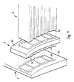
- a first profile 1 has several chambers and is formed on its side surfaces with ribs and grooves.
- the end face of the profile 1 is designated 1a.
- a second profile 2 is shown closed on its end face. It has a curved surface 2a which points in the direction of the end face 1a of the first profile 1.
- a welding mirror designated 3 is provided between the surface 2a and the end face 1a.
- the welding mirror has on its right side according to FIG. 1 a smooth curved surface 3b, the curvature of which corresponds identically to the curvature of the surface 2a.
- the welding mirror 3 On the side facing the surface 2a, the welding mirror 3 has a surface 3c which corresponds exactly in shape to the outer contour of the first profile 1.
- the spatial design of the side 3c corresponds completely to the surface shape of 3b and thus both to the surface shape of the surface 2a and the end surface 1a.
- these surfaces are flat surfaces which slope in an arc towards the top. Of course, other surface shapes are also possible.
- Figure 2 shows a schematic representation of the clamping of the profiles 1 and 2 on a machine table, wherein in the position shown the welding mirror with the surface 3c rests on the surface 2a of the second profile and with the surface 3b on the end face 1a of the first profile.
- the first profile 1 is held in the receptacle 7 of a fixed machine table area 6 with the aid of a schematically indicated clamping cylinder 9.
- a machine table area 4 with a receptacle 5 that can be moved in the direction of the double arrow.
- the second profile 2 is fixed in the receptacle 5 with the aid of the clamping cylinder 8.
- the two surfaces 3c and 3b of the welding mirror 3 heat the areas to be heated.
- the end face 1a of the first profile 1 is heated over the entire surface.
- the area of the surface 2a heated by the surface 3c of the welding mirror 3 is shown in dashed lines and designated 2b.
- the machine table 4 moves to the left in accordance with FIG.
- the welding mirror 3, which is movable in the direction of the double arrow 3a, is moved down between the two profiles.
- the machine table 4a then moves to the right so far that the melted end face 1a and the likewise melted area 2b lie directly against one another and can fuse with one another.
Landscapes
- Engineering & Computer Science (AREA)
- Mechanical Engineering (AREA)
- Lining Or Joining Of Plastics Or The Like (AREA)
Abstract
Description
- Die Erfindung betrifft ein Verfahren zum Verschweißen von Profilen, insbesondere von Kunststoffprofilen für Fenster, Türen oder dergleichen, bei dem beide miteinander zu verschweißenden Profilbereiche bis auf Schweißtemperatur erwärmt und nach dem Erwärmen zusammengefügt werden.
- Bei einer gängigen Technik zur Bildung von Rahmenecken, werden die miteinander zu verbindenen Profile auf Gehrung geschnitten und im Bereich der Gehrungsfuge verschweißt. Diese Technik wird sowohl bei Metallprofilen als auch bei Kunststoffprofilen angewendet.
- Ein Verschweißen der Profile im Eckbereich setzt voraus, daß die zu verbindenden Profile im Verschweißbereich gleiche geometrische Ausbildungen aufweisen müssen. Wenn diese Voraussetzung nicht erfüllt ist und unterschiedliche Profilgeometrien vorliegen, war es bisher erforderlich, die Profile durch einen der Verschweißung vorausgehenden Trennschnitt so in Übereinstimmung zu bringen, daß danach die Eckbereiche dicht verschweißt werden konnten. In vielen Fällen war es nicht möglich, den Trennschnitt so auszubilden, daß eine dichte Verschweißung möglich wurde. In diesen Fällen hat man häufig auf das Verschweißen verzichten müssen und die Profile an den Ecken miteinander verschraubt.
- Ausgehend von diesem Stand der Technik liegt der Erfindung die Aufgabe zugrunde, ein Verfahren der eingangs erwähnten Art so auszubilden, daß mit seiner Hilfe auch Profile unterschiedlicher Geometrie dicht miteinander verschweißt werden können.
- Die Lösung erfolgt mit den Merkmalen des Kennzeichnungsteils von Anspruch 1.
- Das erfindungsgemäße Verfahren erlaubt eine dichte Schweißverbindung zur Bildung einer Ecke zwischen zwei Profilen, die unterschiedlich gestaltet sind. Im Gegensatz zu den bisher bekannten Schweißverbindungen liegt dabei die Schweißfuge nicht in der Gehrungsfuge sondern zwischen der üblicherweise geschlossenen Oberfläche des zweiten Profils und der Stirnfläche des ersten Profils. Dabei ist die Stirnfläche des ersten Profils räumlich so gestaltet wie die zur Stirnfläche weisende Oberfläche des zweiten Profils. Wenn beispielsweise die Oberfläche des zweiten Profils eine S-förmige Kontur aufweist, muß die Stirnfläche des ersten Profils, die auf die S-förmige Oberfläche aufgesetzt wird, in gleicher Weise S-förmig ausgebildet sein. Die Stirnfläche des ersten Profils wird üblicherweise vollständig erwärmt, zumindest jedoch in den außen liegenden Randbereichen. Demgegenüber wird die gegenüberliegende Oberfläche des zweiten Profils nur in demjenigen Bereich erwärmt und bei Kunststoff angeschmolzen, auf den nach dem Erwärmen die Stirnfläche des ersten Profils liegt.
- Bei einer bevorzugten Ausführungsform der Erfindung erfolgt das Erwärmen der zusammenzufügenden Bereiche mittels eines Schweißspiegels,der zum Eintauchen zwischen die miteinander zu verbindenen Profile und zum Anlegen an die zu erwärmenden Bereiche ausgebildet ist, wobei der Schweißspiegel auf beiden Seiten eine Form aufweist, die der Oberflächenform des zweiten Profils entspricht und wobei der zur Oberfläche des zweiten Profils weisende Bereich des Schweißspiegels in seinem Umriß der Außenkontur des ersten Profils entspricht.
- Weitere Merkmale der Erfindung sind in den weiteren Unteransprüchen beschrieben.
- Nachstehend wird eine bevorzugte Ausführungsform der Erfindung anhand der Zeichnung im einzelnen beschrieben. Es zeigen:
- Figur 1 eine perspektivische Teilansicht eines Teilstücks des ersten Profils und des zweiten Profils mit einem zwischen diesen beiden befindlichen Schweißspiegel,
- Figur 2 eine schematische seitliche Darstellung der Profilbereiche während der Erwärmungsphase mittels des Schweißspiegels.
- Ein erstes Profil 1 besitzt mehrere Kammern und ist an seinen Seitenflächen mit Rippen und Nuten ausgebildet. Die Stirnfläche des Profils 1 ist mit 1a bezeichnet.
- Ein zweites Profil 2 ist an seiner Stirnseite geschlossen dargestellt. Es besitzt eine gewölbte Oberfläche 2a, die in Richtung der Stirnseite 1a des ersten Profils 1 weist.
- Zwischen der Oberfläche 2a und der Stirnfläche 1a ist ein mit 3 bezeichneter Schweißspiegel vorgesehen. Der Schweißspiegel besitzt an seiner gemäß Figur 1 rechten Seite eine glatte gekrümmte Oberfläche 3b, deren Krümmung identisch der Krümmung der Oberfläche 2a entspricht. Auf der zur Oberfläche 2a weisenden Seite besitzt der Schweißspiegel 3 eine Oberfläche 3c, welche in ihrer Form genau der Außenkontur des ersten Profils 1 entspricht. Darüberhinaus entspricht die Seite 3c in ihrer räumlichen Gestaltung vollständig der Flächenform von 3b und damit sowohl der Flächenform der Oberfläche 2a und der Stirnfläche 1a. Im dargestellten Ausführungsbeispiel handelt es sich bei diesen Flächen um ebene Flächen, die nach oben hin bogenförmig abfallen. Selbstverständlich sind auch andere Oberflächenformen möglich.
- Figur 2 zeigt in schematischer Darstellung die Aufspannung der Profile 1 und 2 auf einem Maschinentisch, wobei in der dargestellten Position der Schweißspiegel mit der Oberfläche 3c an der Oberfläche 2a des zweiten Profils anliegt und mit der Oberfläche 3b an der Stirnfläche 1a des ersten Profils.
- Das erste Profil 1 ist mit Hilfe eines schematisch angedeuteten Spannzylinders 9 in der Aufnahme 7 eines feststehenden Maschinentischbereichs 6 gehalten. Neben dem feststehenden Maschinentischbereich 6 befindet sich ein in Richtung des Doppelpfeils beweglicher Maschinentischbereich 4 mit einer Aufnahme 5. In der Aufnahme 5 ist das zweite Profil 2 mit Hilfe des Spannzylinders 8 fixiert.
- In der dargestellten Position erwärmen die beiden Oberflächen 3c und 3b des Schweißspiegels 3 die zu erwärmenden Bereiche. Die Stirnfläche 1a des ersten Profils 1 wird vollflächig erwärmt. In Figur 1 ist der von der Oberfläche 3c des Schweißspiegels 3 erwärmte Bereich der Oberfläche 2a gestrichelt dargestellt und mit 2b bezeichnet.
- Nach dem Erwärmen der zu verschweißenden Flächen fährt der Maschinentisch 4 gemäß Figur 2 nach links. Es wird der Schweißspiegel 3, der in Richtung des Doppelpfeils 3a beweglich ist, nach unten zwischen den beiden Profilen herausgefahren. Anschließend fährt der Maschinentisch 4a soweit nach rechts vor, daß die angeschmolzene Stirnfläche 1a und der ebenfalls angeschmolzene Bereich 2b direkt aneinander liegen und miteinander verschmelzen können.
- Anschließend werden die Spannzylinder 8 und 9 gelöst und die Ecke kann entnommen werden.
Claims (4)
dadurch gekennzeichnet,
daß die Stirnfläche (1a) des ersten Profils (1) und eine hierzu quer verlaufende Oberfläche (2a) des zweiten Profils (2) erwärmt werden, wobei die Profilierung der Oberfläche (2a) des zweiten Profils (2) zumindest teilweise übereinstimmt mit der Stirnflächenprofilierung des ersten Profils (1a) und die Erwärmung des zweiten Profils (2) beschränkt ist auf einen Oberflächenbereich, der nach Lage und Gestalt der Stirnfläche (1a) des ersten Profils entspricht.
dadurch gekennzeichnet,
daß das Erwärmen der zusammenzufügenden Bereiche mittels eines Schweißspiegels (3) erfolgt, der zum Eintauchen zwischen die miteinander zu verbindenen Profile (1 und 2) und zum Anlegen an die zu erwärmenden Bereiche ausgebildet ist, wobei der Schweißspiegel (3) auf beiden Seiten (3b und 3c) eine Form aufweist, die der Oberflächenform des zweiten Profils (2) entspricht, wobei der zur Oberfläche (2a) des zweiten Profils (2) weisende Bereich des Schweißspiegels in seinem Umriß der Außenkontur des ersten Profils entspricht.
dadurch gekennzeichnet,
daß das erste Profil (1) und das zweite Profil (2) unter Bildung eines rechten Winkels miteinander verschweißt werden.
dadurch gekennzeichnet,
daß die zum ersten Profil (1) weisende Oberfläche (2a) des zweiten Profils (2) als glatte Fläche ausgebildet ist.
Applications Claiming Priority (2)
| Application Number | Priority Date | Filing Date | Title |
|---|---|---|---|
| DE3914826 | 1989-05-05 | ||
| DE3914826A DE3914826C1 (de) | 1989-05-05 | 1989-05-05 |
Publications (2)
| Publication Number | Publication Date |
|---|---|
| EP0395995A2 true EP0395995A2 (de) | 1990-11-07 |
| EP0395995A3 EP0395995A3 (de) | 1991-08-07 |
Family
ID=6380146
Family Applications (1)
| Application Number | Title | Priority Date | Filing Date |
|---|---|---|---|
| EP19900107735 Withdrawn EP0395995A3 (de) | 1989-05-05 | 1990-04-24 | Verfahren zum Verschweissen von Profilen, insbesondere Kunststoffprofilen |
Country Status (4)
| Country | Link |
|---|---|
| US (1) | US5439546A (de) |
| EP (1) | EP0395995A3 (de) |
| CA (1) | CA2016054C (de) |
| DE (1) | DE3914826C1 (de) |
Cited By (1)
| Publication number | Priority date | Publication date | Assignee | Title |
|---|---|---|---|---|
| DE9209471U1 (de) * | 1992-07-15 | 1992-12-10 | Kommanditgesellschaft Hassomat Maschinenbau GmbH & Co., 2000 Hamburg | T-Verbindung aus Profilen aus Kunststoff, insbesondere für Fensterrahmen |
Families Citing this family (12)
| Publication number | Priority date | Publication date | Assignee | Title |
|---|---|---|---|---|
| EP0685319A3 (de) * | 1994-05-11 | 1998-09-30 | WILLI STÜRTZ MASCHINENBAU GmbH | Verfahren und Vorrichtung zur Herstellung von rechteckigen Rahmen |
| AU4904896A (en) * | 1995-01-27 | 1996-08-14 | Andersen Corporation | Vibratory welded window and door joints, method and apparatus for manufacturing the same |
| US6086703A (en) * | 1997-04-23 | 2000-07-11 | Willi Sturtz Maschinenbau GmbH | Method and apparatus for manufacturing window frames from plastic sections |
| AT2466U1 (de) * | 1997-06-18 | 1998-11-25 | Technoplast Kunststofftechnik | Vorrichtung zum gleichzeitigen verschweissen von mindestens vier auf gehrung geschnittenen profilabschnitten |
| US6006408A (en) * | 1998-03-06 | 1999-12-28 | Wegoma, Inc. | Vinyl window frame weld seam cleaner |
| DE19820198B4 (de) * | 1998-05-06 | 2004-02-19 | Branson Ultraschall Niederlassung Der Emerson Technologies Gmbh & Co | Vorrichtung zum Verschweißen großflächiger Spritzgußbauteile aus Kunststoff |
| US6119752A (en) | 1998-06-09 | 2000-09-19 | Zollinger; Rolf A. | Tool for welding plastic members |
| BE1012079A3 (fr) * | 1998-07-22 | 2000-04-04 | Solvay | Machine de soudage d'objets creux et procede pour souder ces objets. |
| DE19938100A1 (de) * | 1999-08-12 | 2001-02-15 | Exama Maschinen Gmbh | Mehrkopf-Reibschweißverfahren |
| US8747584B2 (en) | 2006-02-03 | 2014-06-10 | Springseal, Inc. | Flashless welding method and apparatus |
| US7503992B2 (en) * | 2006-02-03 | 2009-03-17 | Springseal, Inc. | Flashless welding method and apparatus |
| US8409393B2 (en) * | 2010-12-03 | 2013-04-02 | Yachiyo Industry Co., Ltd. | Method of welding a component part to a plastic fuel tank |
Family Cites Families (14)
| Publication number | Priority date | Publication date | Assignee | Title |
|---|---|---|---|---|
| GB796304A (en) * | 1956-04-16 | 1958-06-11 | Sidney Edward Youthed | An improved method and means for jointing thermoplastic synthetic resin pipes, pipe fittings and the like |
| US3616024A (en) * | 1969-07-14 | 1971-10-26 | Phillips Petroleum Co | Method and apparatus for welding heat sealable pipes |
| US3723229A (en) * | 1970-05-01 | 1973-03-27 | W Hutton | Fusion tool |
| US4390578A (en) * | 1980-03-13 | 1983-06-28 | Blacknell Buildings Limited | Method of joining members |
| NO824291L (no) * | 1981-12-29 | 1983-06-30 | Dainichi Nippon Cables Ltd | Adhesiv og fremgangsmaate for sammenfoeyning av polyolefin-gjenstander ved anvendelse derav |
| US4645557A (en) * | 1983-03-14 | 1987-02-24 | Pedersen Hans N | Method of establishing sealed pipe lengths of plastic pipes by joining of pipe elements, particularly district heating pipe lengths |
| DE3614673A1 (de) * | 1986-04-30 | 1987-11-05 | Urban Maschinenbau | Verfahren und vorrichtung zur herstellung von fensterrahmen od. dgl. |
| DE3634793A1 (de) * | 1986-10-11 | 1988-04-14 | Urban Maschinenbau | Verfahren zum verschweissen von kunststoffprofilen |
| US4753697A (en) * | 1987-02-24 | 1988-06-28 | Denco, Inc. | Total-containment sterile process and system |
| US4909892A (en) * | 1987-05-27 | 1990-03-20 | Sampson Machine Company | Apparatus for welding thermoplastic frame members |
| US4913756A (en) * | 1987-09-22 | 1990-04-03 | Denco, Inc. | Techniques for welding thermoplastic tubes |
| GB2214863B (en) * | 1988-02-19 | 1991-09-04 | British Gas Plc | Joining polyolefinic members by fusion |
| US4963219A (en) * | 1988-05-05 | 1990-10-16 | Duro-Last Roofing, Inc. | Method of making and assembling roof edge structures incorporated with single-ply polymer-coated fabric roof structures |
| US4971639A (en) * | 1989-02-28 | 1990-11-20 | Sampson Machine Company | Method and apparatus for joining polymeric substrates such as vinyl frames |
-
1989
- 1989-05-05 DE DE3914826A patent/DE3914826C1/de not_active Expired - Fee Related
-
1990
- 1990-04-24 EP EP19900107735 patent/EP0395995A3/de not_active Withdrawn
- 1990-05-04 CA CA002016054A patent/CA2016054C/en not_active Expired - Fee Related
-
1994
- 1994-12-02 US US08/353,314 patent/US5439546A/en not_active Expired - Fee Related
Cited By (1)
| Publication number | Priority date | Publication date | Assignee | Title |
|---|---|---|---|---|
| DE9209471U1 (de) * | 1992-07-15 | 1992-12-10 | Kommanditgesellschaft Hassomat Maschinenbau GmbH & Co., 2000 Hamburg | T-Verbindung aus Profilen aus Kunststoff, insbesondere für Fensterrahmen |
Also Published As
| Publication number | Publication date |
|---|---|
| CA2016054A1 (en) | 1990-11-05 |
| EP0395995A3 (de) | 1991-08-07 |
| CA2016054C (en) | 1999-08-03 |
| US5439546A (en) | 1995-08-08 |
| DE3914826C1 (de) | 1990-10-18 |
Similar Documents
| Publication | Publication Date | Title |
|---|---|---|
| DE69032545T2 (de) | Extrudierter knotenpunkt | |
| DE69318397T2 (de) | Verfahren zur genauen verbindung von zwei blechen | |
| EP0233339B1 (de) | Werkstück mit Rippen und Verfahren zu seiner Herstellung | |
| EP0395995A2 (de) | Verfahren zum Verschweissen von Profilen, insbesondere Kunststoffprofilen | |
| DE69413458T2 (de) | Aufbau und Verfahren zum Zusammenfügen von Strangpressprofilen | |
| DE19753111A1 (de) | Lagerbuchse mit Mittelbund sowie deren Verwendung und Herstellungsverfahren | |
| DE69307851T2 (de) | Verfahren zum Herstellen einer geschweissten Struktur, hergestellte Struktur sowie ihre Anwendung zum Herstellen von Knotenpunkt einer Gitterstruktur | |
| DE29808828U1 (de) | Rohr-Kuppeleinrichtung | |
| DE69800803T2 (de) | Verfahren zum aneinander verbinden zwei rohrformige werkstücken sowie mechanischer bauteil aus zwei verbundenen rohrformigen werkstücken | |
| DE3220256C2 (de) | ||
| DE2837061A1 (de) | Aussenhautschweissverbindung | |
| DE19818597C1 (de) | Verbindungselement | |
| DE19526795C1 (de) | Verbundprofil und Verfahren zur Herstellung desselben | |
| DE3322572C2 (de) | Verfahren und Vorrichtung zum bogenförmigen Umformen eines aus einem thermoplastischen Kunststoff bestehenden Profilstrangabschnittes mit Hohlkammern | |
| DE4401667C2 (de) | Abstandshalterrahmen für eine Isolierscheibe und Vorrichtung zu seiner Herstellung | |
| DE69414395T2 (de) | Verfahren zur bearbeitung von hohlprofilen, zur formung von rahmen und entsprechende rahmen und hohlprofile | |
| DE20206377U1 (de) | Vorrichtung zum Verbinden eines Querholms mit Rahmenteilen eines Fensterrahmens, Türrahmens o.dgl. | |
| DE2710544A1 (de) | Verfahren zum herstellen von ausnehmungen, insbesondere an profilen und werkzeug zur durchfuehrung dieses verfahrens | |
| DE3024736C2 (de) | Vorrichtung zur Herstellung von Eckverbindungen von Abdichtungsprofilen für Fenster, Türen o.dgl. | |
| DE2016708C3 (de) | Karosserieprofil, insbesondere für die Karosserie von Kraftfahrzeugen | |
| DE19637811A1 (de) | Verfahren zur Herstellung von Blechteilen | |
| DE19946770A1 (de) | Trägerapparatur von Abstreiferlippen bei beweglichen Schutzeinrichtungen für Maschinenführungen und entsprechendes Herstellverfahren | |
| DE4430256A1 (de) | Verfahren zur Herstellung eines Scharniers für Kraftfahrzeugtüren | |
| DE69905814T2 (de) | Verstellbare Eck-Verbindung für Kabelkanäle | |
| DE69101133T2 (de) | Garagentür. |
Legal Events
| Date | Code | Title | Description |
|---|---|---|---|
| PUAI | Public reference made under article 153(3) epc to a published international application that has entered the european phase |
Free format text: ORIGINAL CODE: 0009012 |
|
| AK | Designated contracting states |
Kind code of ref document: A2 Designated state(s): AT BE CH DE DK ES FR GB GR IT LI LU NL SE |
|
| PUAL | Search report despatched |
Free format text: ORIGINAL CODE: 0009013 |
|
| AK | Designated contracting states |
Kind code of ref document: A3 Designated state(s): AT BE CH DE DK ES FR GB GR IT LI LU NL SE |
|
| 17P | Request for examination filed |
Effective date: 19920206 |
|
| 17Q | First examination report despatched |
Effective date: 19930803 |
|
| STAA | Information on the status of an ep patent application or granted ep patent |
Free format text: STATUS: THE APPLICATION HAS BEEN WITHDRAWN |
|
| 18W | Application withdrawn |
Withdrawal date: 19950301 |