EP0396049A2 - Modem à grande vitesse à porteuses multiples - Google Patents
Modem à grande vitesse à porteuses multiples Download PDFInfo
- Publication number
- EP0396049A2 EP0396049A2 EP90108103A EP90108103A EP0396049A2 EP 0396049 A2 EP0396049 A2 EP 0396049A2 EP 90108103 A EP90108103 A EP 90108103A EP 90108103 A EP90108103 A EP 90108103A EP 0396049 A2 EP0396049 A2 EP 0396049A2
- Authority
- EP
- European Patent Office
- Prior art keywords
- waveform
- frame
- signal
- frequency
- signals
- Prior art date
- Legal status (The legal status is an assumption and is not a legal conclusion. Google has not performed a legal analysis and makes no representation as to the accuracy of the status listed.)
- Withdrawn
Links
Images


Classifications
-
- H—ELECTRICITY
- H04—ELECTRIC COMMUNICATION TECHNIQUE
- H04L—TRANSMISSION OF DIGITAL INFORMATION, e.g. TELEGRAPHIC COMMUNICATION
- H04L27/00—Modulated-carrier systems
- H04L27/26—Systems using multi-frequency codes
- H04L27/2601—Multicarrier modulation systems
- H04L27/2626—Arrangements specific to the transmitter only
-
- H—ELECTRICITY
- H04—ELECTRIC COMMUNICATION TECHNIQUE
- H04L—TRANSMISSION OF DIGITAL INFORMATION, e.g. TELEGRAPHIC COMMUNICATION
- H04L27/00—Modulated-carrier systems
- H04L27/26—Systems using multi-frequency codes
- H04L27/2601—Multicarrier modulation systems
- H04L27/2602—Signal structure
-
- H—ELECTRICITY
- H04—ELECTRIC COMMUNICATION TECHNIQUE
- H04L—TRANSMISSION OF DIGITAL INFORMATION, e.g. TELEGRAPHIC COMMUNICATION
- H04L27/00—Modulated-carrier systems
- H04L27/26—Systems using multi-frequency codes
- H04L27/2601—Multicarrier modulation systems
- H04L27/2647—Arrangements specific to the receiver only
- H04L27/2649—Demodulators
- H04L27/265—Fourier transform demodulators, e.g. fast Fourier transform [FFT] or discrete Fourier transform [DFT] demodulators
-
- H—ELECTRICITY
- H04—ELECTRIC COMMUNICATION TECHNIQUE
- H04L—TRANSMISSION OF DIGITAL INFORMATION, e.g. TELEGRAPHIC COMMUNICATION
- H04L27/00—Modulated-carrier systems
- H04L27/26—Systems using multi-frequency codes
- H04L27/2601—Multicarrier modulation systems
- H04L27/2647—Arrangements specific to the receiver only
- H04L27/2655—Synchronisation arrangements
- H04L27/2656—Frame synchronisation, e.g. packet synchronisation, time division duplex [TDD] switching point detection or subframe synchronisation
-
- H—ELECTRICITY
- H04—ELECTRIC COMMUNICATION TECHNIQUE
- H04L—TRANSMISSION OF DIGITAL INFORMATION, e.g. TELEGRAPHIC COMMUNICATION
- H04L27/00—Modulated-carrier systems
- H04L27/26—Systems using multi-frequency codes
- H04L27/2601—Multicarrier modulation systems
- H04L27/2647—Arrangements specific to the receiver only
- H04L27/2655—Synchronisation arrangements
- H04L27/2657—Carrier synchronisation
Definitions
- This invention relates to a high speed data modem for transmitting and receiving data over common, band-limited telephone channels and the like, and more particularly to a modem which achieves high speed by reducing intersymbol gaps and delays without the normally attendant distortion.
- Modems (an acronym for modulation/demodulation) were developed to enable transmitting digital data over low-grade, but pervasive, analog telephone voice channels. With the ability to transmit data over telephone channels, not only was the need for specially designed data transmission networks eliminated, or at least reduced, but also the number of possible originating and destination stations was greatly multiplied, limited only by the availability (or more precisely nonavailability) of a telephone line.
- Modems operate by transforming binary (two-level) digital data signals into analog signals suitable for transmission over telephone channels and then, after transmission, transforming the analog signals back into the digital data signals. This conversion involves modulating or encoding the digital data onto a carrier signal or signals at the transmitting end, and demodulating or decoding the transmitted signals at the receiving end to recover the desired digital data.
- group delay distortion One of the problems which inhibits improvement in speed and accuracy of data transmission over telephone channels, at least for those systems which utilize multiple carriers (frequencies), is what is denoted “group delay distortion”. This type of distortion comes about because of the difference in phase delay for different frequencies. The result of such distortion is that different frequencies of a transmitted composite analog signal arrive at the receiving end at different times, some frequencies lagging behind others, so that one signal symbol or frame may interfere with an immediately preceding or succeeding symbol, e.g., the late arriving frequencies of a symbol interfering with the early arising frequencies of a succeeding symbol.
- a multi-carrier high speed modem which provides, at the transmitting end, for generating sets of carrier signals where each carrier signal of a set has a frequency different from the frequency of every other carrier signal of the set, modulating each carrier signal of a set with a different portion of digital data to be transmitted, all such portions which are used to modulate a set of carrier signals constituting a frame of digital data, and successively combining together the modulated carrier signals of each set to produce a frame waveform.
- Each frame waveform is successively transformed pursuant to an inverse Fast Fourier Transform function from a frequency domain signal to a time domain signal.
- each transformed waveform is rotated (linear phase shifted) so that its beginning point and slope substantially match the ending point and slope of the immediately preceding transformed waveform.
- the rotated waveforms are then transmitted with no gap or spacing between waveforms, to a receiving station.
- the received waveforms are rerotated substantially to their original condition before rotating.
- the received, rerotated waveforms are then transformed, pursuant to a Fast Fourier Transform function from the time domain back to the frequency domain.
- the received, rerotated and transformed waveforms are demodulated to recover the digital data information.
- some reference frequencies are added to the waveforms before rotation and some are added to the rotated waveforms, all at the transmitting end. Then at the receiving end, the phase and amplitude of the reference frequencies, which are constant from frame to frame, allow determination of the amount of rotation which has occurred on each waveform. As a result, each waveform may be properly rerotated.
- the system of the present invention is designed for the transmission of digital data over conventional telephone channels such as would be available on the switched telephone network.
- a specific illustrative embodiment of the system of the present invention allows for transmitting at a speed of 19.2 kilobits per second by employing sets or frames of constant frequency carrier signals, for example, 186 per frame.
- the carrier signals are amplitude and phase modulated or encoded with binary data, for example, 7 bits per carrier signal to thus yield 1302 bits per frame.
- the frequency spacing between carrier signals is some fixed amount, for example 15.625 Hz, with the lowest carrier signal frequency set, for example, at 312.5 Hz and the highest carrier signal frequency set at 3203 Hz.
- the carrier signals of a frame are summed to obtain a frame waveform for ultimate transmission to a receiving station where the digital data may be recovered.
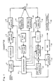
- FIG. 1 shows one specific illustrative embodiment of a modem transmitter constructed in accordance with the present invention.
- the transmitter includes a frame buffer 4 for receiving, temporarily storing, and grouping or framing input serial binary data.
- the grouping or framing of the input data is carried out under control of a microprocessor 8 which, for example, could be a Texas Instruments' DSP chip 320C255.
- a microprocessor 8 which, for example, could be a Texas Instruments' DSP chip 320C255.
- the encoding or modulation capacity designated above was for 1302 bits per frame, and so if it is determined that 1229 data bits per frame will be transmitted, there will be 73 surplus bits available in every frame. These surplus bits will be used for error detection and correction purposes as will be described later.
- the frame buffer 4 should have a capacity to temporarily store at least 1229 bits of data. However, due to commonly occurring inaccuracies with timing clocks, the frame buffer 4 should be selected to store several extra bits, for example 1232, to compensate for the timing inaccuracies.
- the frame buffer 4 unloads its stored data, a frame at a time, to a scrambler 8 which randomizes the data in a well known manner to avoid transmission of long sequences of constant or nonvarying data.
- the scrambled data is supplied to an error detection/correction encoder 12 which adds redundant bits for purposes of error detection and correction. For example, in accordance with the parameter specified above, if each frame includes 1232 bits of data, then 70 bits of redundancy could be added to provide a total of 1302 bits per frame and achieve the desired transmission rate of 19.2 kilobits per second.
- the error detection and correction encoding could be carried out using a variety of well known encoding techniques, such as block parity or convolutional encoding. Although the encoding function, as well as the scrambler function, is shown as being carried out by individual units, such functions could also be carried out by the microprocessor 8.
- the encoded data is supplied to a QAM modulator 16 which divides each frame (1302 bits) into 7-bit subsets, where each subset is encoded onto a different one of the carrier frequencies.
- QAM which stands for quadrature amplitude modulation
- amplitude and phase modulates each of the carrier frequencies with the data bit subsets in accordance, for example, with an equidistant signal constellation such as shown in FIG. 3.
- each intersection of the block lines, plus the four end points of the center horizontal line 300 and the center vertical line 304 define 128 different phase (angular position of a point) and amplitude (distance from center of constellation to the point) for each of 128 different 7-bit data words.
- each 7-bit data word is assigned a different phase and amplitude in accordance with the constellation and that phase and amplitude is used to modulate one of the carrier frequencies when the corresponding 7-bit word is to be transmitted.
- the 128 different points are spaced as far apart from every other point as possible in phase and amplitude.
- QAM modulation is also well known; see, for example, U.S. Patent No. 4,085,449.
- modulation by the modulator 16 has been described as though a continuous waveform or carrier signal is being modulated (and this will be the ultimate result), but at this stage of the operation of the transmitter of FIG. 1, such operations would be carried out digitally and then later, as will be described, the digital information will be converted to an analog signal.
- the carrier signals are supplied to an adder 20, along with two reference frequencies developed by a reference frequency 1 generator 24 and a reference frequency 2 generator 28, which sums all the frequencies to produce a composite frame (or symbol) signal.
- the reference frequencies 1 and 2 are different from one another and are provided to facilitate rotation and inverse rotation or "rerotation" of the composite frame signals, as will be described later.
- Each composite frame signal is supplied by the adder 20 to an adaptive equalizer circuit 32 which "predistorts" the composite signals to be transmitted to compensate for the attenuation effects of typical telephone communication channels.
- This predistortion involves changing amplitudes of the carrier frequency signals to account beforehand of amplitude distortion which will occur on a telephone communication channel.
- the average attenuation as a function of frequency for a communication channel can be determined and the inverse of this function is multiplied with each real and imaginary component of the modulated signals so that after transmission and the expected attenuation, the receiver will receive frequency signals which are closer to those transmitted than would be the case without the predistortion.
- the adaptive equalizer 32 supplies the composite frame signals to an inverse Fast Fourier Transform circuit 44 which converts the signals from the frequency domain to the time domain.
- a transmitter clock rate of 8 KHz is selected (thus an 8 KHz oscillator 36 is provided), with each frame consisting of 512 clock cycles (a divider 40 provides a signal to the microprocessor 8 at the beginning and end of each frame, i.e., every 512 clock cycles).
- the adaptive equalizer 32 supplies to the inverse Fast Fourier Transform circuit 44 successive composite frame signals composed of 512 frequency domain samples consisting of the real and imaginary components of 256 frequencies. These composite frame signals are transformed by the circuit 44 into 512 digital time domain samples per frame and these are supplied to a rotate and match buffer circuit 48.
- the circuit 48 under control of the microprocessor 8, successively stores the composite frame signals (represented by the 512 time domain samples) in buffers for the purpose of matching the amplitude and slope of the end of each frame signal with the amplitude and slope of the next succeeding frame signal. This is accomplished by rotating (phase shifting) each succeeding frame signal until a fairly close match is achieved. If the frame signals are thought of as continuous frame waveforms (as they will ultimately be), then the beginning point of each frame waveform can be viewed as being shifted until a point in the waverform is reached where the amplitude and slope at that point closely matches the amplitude and slope of the ending point of the just preceding frame waveform.
- each composite frame signal will begin and end at the same amplitude and so the signal may be rotated to define a new beginning and ending for the signal and that new beginning and ending will have essentially the same amplitude and slope.
- composite frame signals may be rotated (successively phase shifted) so that their new beginning points match in amplitude and slope the ending points of the preceding frame signals; and then the transmitted frame signals may be inversely rotated or "rerotated" at the receiving end to recover the original frame signals or waveforms.
- each composite frame signal has been randomized (by the scrambler 8), statistically there will likely be several points in the time domain frame signal where the amplitude and slope will match the ending amplitude and slope of the just previous frame signal.
- the rotate and match buffer circuit 48 simply rotates each frame signal until the slope and amplitude of the beginning two or three samples (of the 512 total) of the frame substantially match the ending two or three samples of the just previous frame.
- equalization, FFT and rotate and match functions are shown as being carried out by individual units, these functions could all be performed by the microprocessor 8 if desired.
- the frame signal being rotated is ready for application to an adder 52.
- the adder 52 adds each rotated frame signal (assuming rotation is required) to a third reference frequency supplied by reference frequency 3 generator 56.
- This reference frequency is provided for synchronization purposes, i.e., to identify the beginning and ending of each frame. Since the reference frequency 3 will be added to the composite frame signals after any rotation, it can be used to synchronize the receiver with the transmitter.
- the frequency of reference frequency 3 will be selected to include an integer number of periods in one frame time. For example, for the 8 KHz clock rate, and a frame consisting of 512 clock cycles, if the reference frequency number 3 is selected to be 296.875 Hz, then there will be 19 cycles per frame for the reference frequency 3.
- the reference frequency 3 generator 56 supplies a reference frequency signal to the adder 52 such that the polarity of the signal is changed with every frame. In this manner, the beginning and ending of each frame can be readily determined at the receiver as the points of change of polarity of the reference frequency 3 signal, to thus allow synchronization with the transmitter.
- Reference frequency 3 will also be used, in conjunction with reference frequencies 1 and 2, to determine the amount of rotation of each composite frame signal.
- the composite frame signal produced by adder 52 is supplied to a digital to analog converter 60 which produces an analog waveform representation of each frame signal suitable for transmission over a telephone channel.
- the digital to analog converter 60 supplies the waveform to a data access arrangement circuit 64 which connects the transmitter of FIG. 1 to a telephone channel 68.
- the DAA circuit 64 includes circuitry necessary for interfacing with the telephone system for among other things, protection of the system, and is of conventional design.
- FIG. 2 shows a specific illustrative embodiment of a modem receiver constructed in accordance with the present invention.
- the receiver includes a data access arrangement circuit 72 for connecting the rest of the receiver circuitry to the telephone channel 68 over which data signals are transmitted.
- the DAA circuit 72 supplies received signals to a digitally controlled amplifier 76 whose gain is determined by a digital input received from a microprocessor 80.
- the microprocessor 80 as with the microprocessor 8 of FIG. 1, could advantageously be a Texas Instruments' DSP chip 320C255.
- the amplifier 76 amplifies the received signal to a level required by an analog to digital converter 80 to which the amplifier supplies the received signal. This is done by calculating the energy level of a previously converted set of samples from a frame waveform and then computing a new gain value for the next frame waveform. The gain of the amplifier 76 is only changed at frame transition times, i.e., between frames.
- the analog to digital convertor 80 bandlimits the incoming signal and converts it to a sequence of digital values at a sampling rate of 8 KHz, determined by a sampling strobe received from the microprocessor 8.
- the sampled digital signals are supplied to a group delay equalizer circuit 84 which removes the effects of any group delay from a received symbol or frame.
- group delay equalizer circuit 84 which removes the effects of any group delay from a received symbol or frame.
- the received signals are then supplied to a frequency correction circuit 88 which, in a conventional fashion, corrects for any frequency offsets and phase errors which may have occurred in the signals during transmission.
- Tne frequency corrected data is supplied by the frequency correction circuit 88 to a rerotate circuit 92 which buffers the data into 512 sample blocks as defined by the receiver frame timing determined by the microprocessor from a framing signal detector 94.
- each change of polarity of the reference frequency 3 signal is detected by the framing signal detector 94 using, for example, a Costas loop detection arrangement to indicate the end of one frame and the bginning of another frame.
- the framing signal detector 94 signals the microprocessor 80 to indicate the beginning and ending of each frame, and also signals the microprocessor of any frequency shift in reference frequency 3. The latter information is supplied by the microprocessor 80 to the frequency correction circuit 88 to enable it to correct for frequency offset of the composite signal.
- the amount of rotation can be readily determined by examining reference frequencies 1 and 2 which were added to the transmitted signal prior to rotation at the transmitter of FIG. 1, and thus also rotated. Since the two reference frequencies are different, and since the relative phase difference between the two frequencies varies in a uniform way over a frame time period, an examination of this phase difference will reveal the amount of rotation of each frame waveform.
- each received frame waveform would simply be rerotated until reaching that point in the waveform where reference frequencies 1 and 2 had a phase difference of zero--that point would indicate the unrotated beginning of the symbol or frame.
- Each rerotated frame waveform is supplied by the rerotate circuit 92 to a Fast Fourier Transform circuit 96 which converts the data from the time domain back to the frequency domain using a conventional Fast Fourier Transform algorithm.
- the transform data is then supplied to an amplitude and phase correction circuit 100.
- This circuit in a conventional fashion, corrects the amplitude and phase of the received signals by an amount determined from training signal waveforms initially transmitted. This correction may be implemented in the form of a look-up table developed from the initial training sequences transmitted.
- the corrected information is then supplied to a QAM demodulator 104 which demodulates the information by comparing the real and imaginary parts of the individual carriers to a stored signal constellation (FIG.
- the demodulated signals are then supplied to an error detection/correction decoder 108 to determine and correct for any bit errors and the resulting words, stripped of the 70 redundant bits for a total word length of 1232, are supplied to a descrambler 112.
- the descrambler 112 simply performs the opposite of the scrambling function performed at the transmitter, to recover the true data bits which were to be transmitted.
- the data is then supplied to an output frame buffer 116 which performs the inverse of the frame buffer 4 of FIG. 1, i.e., unblocks the data, and then supplies the data as a serial bit stream to a receiving or utilization device (not shown).
- a modem system where no delays or gaps need be inserted between symbols or frames of transmitted data and thus the delay which would otherwise be incurred is avoided.
- Intersymbol or interframe interference which is generally caused by sending a sequence of frames where the amplitude between frames abruptly changes, is also avoided by rotating each frame waveform so that its beginning point, in amplitude and slope, substantially match the amplitude and slope of ending point of the just previous frame waveform.
- the frame waveforms are rerotated to recover the original signals.
Landscapes
- Engineering & Computer Science (AREA)
- Computer Networks & Wireless Communication (AREA)
- Signal Processing (AREA)
- Physics & Mathematics (AREA)
- Discrete Mathematics (AREA)
- General Physics & Mathematics (AREA)
- Mathematical Physics (AREA)
- Digital Transmission Methods That Use Modulated Carrier Waves (AREA)
Applications Claiming Priority (2)
| Application Number | Priority Date | Filing Date | Title |
|---|---|---|---|
| US07/346,069 US4943980A (en) | 1989-05-02 | 1989-05-02 | Multi-carrier high speed modem |
| US346069 | 1989-05-02 |
Publications (2)
| Publication Number | Publication Date |
|---|---|
| EP0396049A2 true EP0396049A2 (fr) | 1990-11-07 |
| EP0396049A3 EP0396049A3 (fr) | 1992-09-16 |
Family
ID=23357801
Family Applications (1)
| Application Number | Title | Priority Date | Filing Date |
|---|---|---|---|
| EP19900108103 Withdrawn EP0396049A3 (fr) | 1989-05-02 | 1990-04-27 | Modem à grande vitesse à porteuses multiples |
Country Status (9)
| Country | Link |
|---|---|
| US (1) | US4943980A (fr) |
| EP (1) | EP0396049A3 (fr) |
| JP (1) | JPH0364145A (fr) |
| KR (1) | KR900019426A (fr) |
| CN (1) | CN1056197A (fr) |
| AU (1) | AU5450890A (fr) |
| BR (1) | BR9002023A (fr) |
| CA (1) | CA2014354A1 (fr) |
| ZA (1) | ZA903332B (fr) |
Cited By (6)
| Publication number | Priority date | Publication date | Assignee | Title |
|---|---|---|---|---|
| EP0603656A3 (fr) * | 1992-12-23 | 1995-05-10 | Grundig Emv | Procédé et dispositif pour l'élimination de la fréquence de décalage des signaux reçus dans un système de transmission numérique. |
| EP0820168A3 (fr) * | 1996-07-19 | 2000-04-12 | Texas Instruments Incorporated | Modem à plusieurs modes de fonctionnement, et protocoles pour celui-ci |
| EP0719003A3 (fr) * | 1994-12-22 | 2000-09-13 | Roke Manor Research Limited | Système radio mobile cellulaire combinant MDFO et évasion de fréquence |
| EP1005205A3 (fr) * | 1998-11-25 | 2003-09-17 | Lucent Technologies Inc. | Initialisation rapide pour systèmes multiporteurs |
| KR100492206B1 (ko) * | 1996-07-19 | 2005-08-05 | 텍사스 인스트루먼츠 인코포레이티드 | 주파수영역무반송파am-pm복조기 |
| EP1713221A1 (fr) * | 2005-04-12 | 2006-10-18 | Siemens Aktiengesellschaft | Procédé de réduction de l'énergie de l'interférence intersymboles |
Families Citing this family (52)
| Publication number | Priority date | Publication date | Assignee | Title |
|---|---|---|---|---|
| EP0407673B1 (fr) * | 1989-07-12 | 1994-05-11 | International Business Machines Corporation | Procédé de synchronisation d'un récepteur modem après un apprentissage sur les données |
| GB9123376D0 (en) * | 1991-11-04 | 1991-12-18 | British Broadcasting Corp | Coding method for broadcast transmissions |
| EP0617531A1 (fr) * | 1993-03-25 | 1994-09-28 | Matsushita Electric Industrial Co., Ltd. | Système de transmission multirésolution |
| US6334219B1 (en) | 1994-09-26 | 2001-12-25 | Adc Telecommunications Inc. | Channel selection for a hybrid fiber coax network |
| US7280564B1 (en) | 1995-02-06 | 2007-10-09 | Adc Telecommunications, Inc. | Synchronization techniques in multipoint-to-point communication using orthgonal frequency division multiplexing |
| USRE42236E1 (en) | 1995-02-06 | 2011-03-22 | Adc Telecommunications, Inc. | Multiuse subcarriers in multipoint-to-point communication using orthogonal frequency division multiplexing |
| US5521908A (en) * | 1995-04-20 | 1996-05-28 | Tellabs Operations Inc. | Method and apparatus for providing reduced complexity echo cancellation in a multicarrier communication system |
| JPH1065588A (ja) * | 1996-08-23 | 1998-03-06 | Sony Corp | 振幅・位相補正回路、受信装置及び送信装置 |
| WO1998010551A2 (fr) * | 1996-09-02 | 1998-03-12 | Telia Ab | Perfectionnements relatifs a des systemes de transmission a porteuses multiples |
| DE69717285T2 (de) * | 1996-09-02 | 2003-09-04 | Stmicroelectronics N.V., Amsterdam | Verbesserungen bei, oder in bezug auf mehrträgerübertragungssysteme |
| US20030026282A1 (en) * | 1998-01-16 | 2003-02-06 | Aware, Inc. | Splitterless multicarrier modem |
| JPH11136180A (ja) * | 1997-10-31 | 1999-05-21 | Sony Corp | データ通信方法、送信装置及びセルラー無線通信システム |
| US6169744B1 (en) | 1998-01-07 | 2001-01-02 | 3Com Corporation | Method and protocol for a medium access control layer for local area networks with multiple-priority traffic |
| US6891887B1 (en) | 1998-05-27 | 2005-05-10 | 3Com Corporation | Multi-carrier LAN adapter device using interpolative equalizer |
| US6507585B1 (en) | 1998-05-27 | 2003-01-14 | 3Com Corporation | Multi-carrier LAN adapter device using frequency domain equalizer |
| US6704317B1 (en) | 1998-05-27 | 2004-03-09 | 3Com Corporation | Multi-carrier LAN modem server |
| US6603811B1 (en) | 1998-05-29 | 2003-08-05 | 3Com Corporation | Low complexity frequency domain equalizer having fast re-lock |
| US6377683B1 (en) | 1998-05-29 | 2002-04-23 | 3Com Corporation | Low complexity frequency domain echo canceller for DMT transceivers |
| US6560276B1 (en) * | 1998-09-25 | 2003-05-06 | Intel Corporation | Synchronization techniques using an interpolation filter |
| US6374312B1 (en) * | 1998-09-25 | 2002-04-16 | Intel Corporation | System for dedicating a host processor to running one of a plurality of modem programs and dedicating a DSP to running another one of the modem programs |
| US6711206B1 (en) | 1998-09-25 | 2004-03-23 | Intel Corporation | Modem using a digital signal processor and separate transmit and receive sequencers |
| US6625208B2 (en) * | 1998-09-25 | 2003-09-23 | Intel Corporation | Modem using batch processing of signal samples |
| US6661848B1 (en) | 1998-09-25 | 2003-12-09 | Intel Corporation | Integrated audio and modem device |
| US6490628B2 (en) * | 1998-09-25 | 2002-12-03 | Intel Corporation | Modem using a digital signal processor and a signal based command set |
| US6502138B2 (en) * | 1998-09-25 | 2002-12-31 | Intel Corporation | Modem with code execution adapted to symbol rate |
| US6711205B1 (en) | 1998-09-25 | 2004-03-23 | Intel Corporation | Tone detector for use in a modem |
| US6667986B1 (en) | 1998-10-01 | 2003-12-23 | Utstarcom Incorporated | System and method for providing high-speed data access using a distributed modem |
| US6553518B1 (en) | 1999-03-08 | 2003-04-22 | International Business Machines Corporation | Severe error detectors, methods and computer program products that use constellation specific error event thresholds to detect severe error events during demodulation of a signal comprising symbols from a plurality of symbol constellations |
| US6661847B1 (en) | 1999-05-20 | 2003-12-09 | International Business Machines Corporation | Systems methods and computer program products for generating and optimizing signal constellations |
| US6674856B1 (en) * | 1999-09-23 | 2004-01-06 | Agere Systems Inc. | Placement of a transmit predistortion filter with respect to a data access arrangement |
| US6839382B1 (en) | 1999-10-29 | 2005-01-04 | International Business Machines Corporation | System, methods and computer program products for identifying digital impairments in modem signals using signature analysis and signal level comparison analysis |
| US6765955B1 (en) | 1999-10-29 | 2004-07-20 | International Business Machines Corporation | Methods, systems and computer program products establishing a communication configuration for a modem connection to compensate for echo noise |
| US6826157B1 (en) | 1999-10-29 | 2004-11-30 | International Business Machines Corporation | Systems, methods, and computer program products for controlling data rate reductions in a communication device by using a plurality of filters to detect short-term bursts of errors and long-term sustainable errors |
| US6505222B1 (en) | 1999-10-29 | 2003-01-07 | International Business Machines Corporation | Systems methods and computer program products for controlling undesirable bias in an equalizer |
| US6650657B1 (en) | 1999-10-29 | 2003-11-18 | International Business Machines Corporation | Systems, methods and computer program products for identifying digital impairments in modem signals |
| US6823004B1 (en) | 1999-10-29 | 2004-11-23 | International Business Machines Corporation | Methods, systems and computer program products for monitoring performance of a modem during a connection |
| US6792040B1 (en) | 1999-10-29 | 2004-09-14 | International Business Machines Corporation | Modems having a dual power mode capability and methods of operating same |
| US6816545B1 (en) | 1999-10-29 | 2004-11-09 | International Business Machines Corporation | Systems, methods and computer program products for identifying digital impairments in modems based on clusters and/or skips in pulse code modulation signal levels |
| US6967995B1 (en) | 1999-10-29 | 2005-11-22 | International Business Machines Corporation | Methods, systems and computer program products for carrier drop detection using a variable threshold |
| US6611563B1 (en) | 1999-10-29 | 2003-08-26 | International Business Machines Corporation | Systems, methods and computer program products for data mode refinement of modem constellation points |
| US6823017B1 (en) | 1999-10-29 | 2004-11-23 | International Business Machines Corporation | Systems, methods and computer program products for filtering glitches from measured values in a sequence of code points |
| US6792004B1 (en) | 1999-10-29 | 2004-09-14 | International Business Machines Corporation | Systems, methods and computer program products for averaging learned levels in the presence of robbed-bit signaling based on proximity |
| US6662322B1 (en) | 1999-10-29 | 2003-12-09 | International Business Machines Corporation | Systems, methods, and computer program products for controlling the error rate in a communication device by adjusting the distance between signal constellation points |
| US6754258B1 (en) | 1999-10-29 | 2004-06-22 | International Business Machines Corporation | Systems, methods and computer program products for averaging learned levels in the presence of digital impairments based on patterns |
| DE10015257A1 (de) * | 2000-03-28 | 2001-10-04 | Rohde & Schwarz | Verfahren zum Übertragen von OFDM-Signalen |
| KR20040004562A (ko) * | 2001-03-27 | 2004-01-13 | 어웨어, 인크. | 수신기 투과성 q-모드 |
| US20060203927A1 (en) * | 2001-03-27 | 2006-09-14 | Aware, Inc. | Systems and methods for implementing receiver transparent Q-mode |
| US7075999B2 (en) | 2002-04-19 | 2006-07-11 | Texas Instruments Incorporated | Multicarrier modulation with data dependent frequency-domain redundancy |
| CN101083504B (zh) * | 2007-07-23 | 2011-09-07 | 沖电气(新加坡)技术中心 | 解调装置及其解调方法 |
| CN108023850B (zh) * | 2017-11-17 | 2021-01-08 | 深圳市锐能微科技有限公司 | 一种无线通信方法及装置 |
| CN108461087B (zh) * | 2018-02-07 | 2020-06-30 | 河南芯盾网安科技发展有限公司 | 数字信号穿过声码器的装置及方法 |
| US10841145B1 (en) * | 2019-06-17 | 2020-11-17 | Envistacom, Llc | Multi-rotational waveform utilizing a plurality of transmission waveforms and transmission paths |
Family Cites Families (5)
| Publication number | Priority date | Publication date | Assignee | Title |
|---|---|---|---|---|
| US4206320A (en) * | 1978-08-21 | 1980-06-03 | University Of Illinois Foundation | High speed modem suitable for operating with a switched network |
| US4381428A (en) * | 1981-05-11 | 1983-04-26 | The United States Of America As Represented By The Secretary Of The Navy | Adaptive quantizer for acoustic binary information transmission |
| US4495620A (en) * | 1982-08-05 | 1985-01-22 | At&T Bell Laboratories | Transmitting data on the phase of speech |
| US4734920A (en) * | 1984-10-10 | 1988-03-29 | Paradyne Corporation | High speed modem for multiple communication circuits |
| US4679227A (en) * | 1985-05-20 | 1987-07-07 | Telebit Corporation | Ensemble modem structure for imperfect transmission media |
-
1989
- 1989-05-02 US US07/346,069 patent/US4943980A/en not_active Expired - Lifetime
-
1990
- 1990-04-11 CA CA002014354A patent/CA2014354A1/fr not_active Abandoned
- 1990-04-27 EP EP19900108103 patent/EP0396049A3/fr not_active Withdrawn
- 1990-04-27 JP JP2110739A patent/JPH0364145A/ja active Pending
- 1990-04-27 AU AU54508/90A patent/AU5450890A/en not_active Abandoned
- 1990-04-28 CN CN90102454A patent/CN1056197A/zh active Pending
- 1990-04-30 BR BR909002023A patent/BR9002023A/pt unknown
- 1990-05-01 KR KR1019900006191A patent/KR900019426A/ko not_active Withdrawn
- 1990-05-02 ZA ZA903332A patent/ZA903332B/xx unknown
Cited By (7)
| Publication number | Priority date | Publication date | Assignee | Title |
|---|---|---|---|---|
| EP0603656A3 (fr) * | 1992-12-23 | 1995-05-10 | Grundig Emv | Procédé et dispositif pour l'élimination de la fréquence de décalage des signaux reçus dans un système de transmission numérique. |
| EP0719003A3 (fr) * | 1994-12-22 | 2000-09-13 | Roke Manor Research Limited | Système radio mobile cellulaire combinant MDFO et évasion de fréquence |
| EP0820168A3 (fr) * | 1996-07-19 | 2000-04-12 | Texas Instruments Incorporated | Modem à plusieurs modes de fonctionnement, et protocoles pour celui-ci |
| SG96176A1 (en) * | 1996-07-19 | 2003-05-23 | Texas Instruments Inc | Multimode digital modem |
| KR100492206B1 (ko) * | 1996-07-19 | 2005-08-05 | 텍사스 인스트루먼츠 인코포레이티드 | 주파수영역무반송파am-pm복조기 |
| EP1005205A3 (fr) * | 1998-11-25 | 2003-09-17 | Lucent Technologies Inc. | Initialisation rapide pour systèmes multiporteurs |
| EP1713221A1 (fr) * | 2005-04-12 | 2006-10-18 | Siemens Aktiengesellschaft | Procédé de réduction de l'énergie de l'interférence intersymboles |
Also Published As
| Publication number | Publication date |
|---|---|
| CN1056197A (zh) | 1991-11-13 |
| ZA903332B (en) | 1991-02-27 |
| BR9002023A (pt) | 1991-08-13 |
| KR900019426A (ko) | 1990-12-24 |
| AU5450890A (en) | 1990-11-08 |
| EP0396049A3 (fr) | 1992-09-16 |
| CA2014354A1 (fr) | 1990-11-02 |
| JPH0364145A (ja) | 1991-03-19 |
| US4943980A (en) | 1990-07-24 |
Similar Documents
| Publication | Publication Date | Title |
|---|---|---|
| US4943980A (en) | Multi-carrier high speed modem | |
| US5128964A (en) | Modulation method and apparatus for multicarrier data transmission | |
| US6501810B1 (en) | Fast frame synchronization | |
| KR960007813B1 (ko) | 직각 진폭 변조 동기화 방법 | |
| US4206320A (en) | High speed modem suitable for operating with a switched network | |
| JP4608167B2 (ja) | ダイレクトシーケンス拡散スペクトルシステムのためのキャリアトラッキングループ | |
| US5063574A (en) | Multi-frequency differentially encoded digital communication for high data rate transmission through unequalized channels | |
| JP2904986B2 (ja) | 直交周波数分割多重ディジタル信号送信装置および受信装置 | |
| EP0877516B1 (fr) | Système de traitement de signal | |
| EP1139624B1 (fr) | Correction d'un décalage en point d'échantillonage dans un système de multiplexage par division en fréquences orthogonaux | |
| US5052024A (en) | Offset frequency multipoint modem and communications network | |
| US20020118658A1 (en) | Modulation/demodulation of a pilot carrier, and means to perform the modulation/demodulation | |
| US6438174B1 (en) | Multi-carrier transmission systems | |
| WO1996016492A1 (fr) | Systeme et procede a mot pilote a codage differentiel pour l'emission radio de donnees numeriques | |
| EP0761043A1 (fr) | Modem haute performance utilisant des symboles pilote pour l'egalisation et la synchronisation de trame | |
| JPH07321762A (ja) | クロック周波数自動制御方式及びそれに用いる送信装置と受信装置 | |
| JP2000517508A (ja) | 多重搬送波伝送システムにおける、あるいはそれに関する改良 | |
| US6590945B1 (en) | Method and apparatus for frequency offset compensation | |
| US6961393B1 (en) | In-band-on-channel (IBOC) system and methods of operation using orthogonal frequency division multiplexing (OFDM) with timing and frequency offset correction | |
| GB2232852A (en) | Offset correction | |
| US6108349A (en) | Method and apparatus for registering remote service units in a multipoint communication system | |
| Gledhill et al. | The transmission of digital television in the UHF band using orthogonal frequency division multiplexing | |
| US4726029A (en) | Error-correcting modem | |
| US20020034160A1 (en) | Apparatus and method for symbol alignment in a multi-point OFDM/DMT digital communications system | |
| JP3130716B2 (ja) | Ofdm送信装置及びofdm受信装置 |
Legal Events
| Date | Code | Title | Description |
|---|---|---|---|
| PUAI | Public reference made under article 153(3) epc to a published international application that has entered the european phase |
Free format text: ORIGINAL CODE: 0009012 |
|
| AK | Designated contracting states |
Kind code of ref document: A2 Designated state(s): AT BE CH DE DK ES FR GB GR IT LI NL SE |
|
| PUAL | Search report despatched |
Free format text: ORIGINAL CODE: 0009013 |
|
| AK | Designated contracting states |
Kind code of ref document: A3 Designated state(s): AT BE CH DE DK ES FR GB GR IT LI NL SE |
|
| STAA | Information on the status of an ep patent application or granted ep patent |
Free format text: STATUS: THE APPLICATION IS DEEMED TO BE WITHDRAWN |
|
| 18D | Application deemed to be withdrawn |
Effective date: 19921105 |