EP0396208A2 - Pflanzmaschine für Setzlinge in Topfballen - Google Patents
Pflanzmaschine für Setzlinge in Topfballen Download PDFInfo
- Publication number
- EP0396208A2 EP0396208A2 EP90201525A EP90201525A EP0396208A2 EP 0396208 A2 EP0396208 A2 EP 0396208A2 EP 90201525 A EP90201525 A EP 90201525A EP 90201525 A EP90201525 A EP 90201525A EP 0396208 A2 EP0396208 A2 EP 0396208A2
- Authority
- EP
- European Patent Office
- Prior art keywords
- machine
- planting
- discs
- clods
- plant
- Prior art date
- Legal status (The legal status is an assumption and is not a legal conclusion. Google has not performed a legal analysis and makes no representation as to the accuracy of the status listed.)
- Withdrawn
Links
Images


Classifications
-
- A—HUMAN NECESSITIES
- A01—AGRICULTURE; FORESTRY; ANIMAL HUSBANDRY; HUNTING; TRAPPING; FISHING
- A01C—PLANTING; SOWING; FERTILISING
- A01C11/00—Transplanting machines
- A01C11/02—Transplanting machines for seedlings
- A01C11/025—Transplanting machines using seedling trays; Devices for removing the seedlings from the trays
Definitions
- the present invention relates to machines intended for mechanically planting seedlings grown in clumps in honeycomb trays, and more particularly an improvement to the device for conveying and depositing seedlings in the ground.
- This machine described in particular in the initial application EP-87 400 919.4 makes it possible to carry out a fully automated planting, reducing the action of the only person assigned to this machine to supply the latter with trays with cells filled with clods. plant.
- This machine of the semi-mounted type consists of a chassis assembly comprising a main chassis equipped with carrying wheels, on which are mounted one or more secondary chassis articulated on said main chassis so as to allow regularity of planting depth whatever regardless of the flatness of the growing board and the variation in height of the latter with respect to the runners on which the carrying wheels of the main chassis run, the chassis assembly thus formed carrying one or more planting units each composed: - a tray holder and clod extraction unit, - a set of clod care and transfer, - a set of conveying and depositing plants on the ground, - a set of soil preparation and leveling.
- the different successive phases from the extraction of clods from the tray to the removal of the plants on the ground being controlled from a programmable controller.
- These different phases consist in a translational routing of the trays filled with plants plumb with a battery of gripping pliers spaced from each other by the spacing value of the cells of the same row of the tray, which pliers, after having each taken a plant by the root ball, tilt while moving away from each other to reach an interval corresponding to that of the buckets fitted to the conveying device inside which buckets the plants are deposited by opening of the clamps.
- the assembly for conveying and depositing the plants on the ground consists of a handling chain carrying, suspended at regular intervals, nacelles or buckets; and circulating in a closed loop in an inclined plane of about 30 ° with respect to the vertical between three toothed wheels along a triangular trajectory comprising a horizontal portion during which the buckets are loaded with plants and two oblique portions competing towards the point of drop to the ground below which the bucket opens.
- a handling chain carrying, suspended at regular intervals, nacelles or buckets; and circulating in a closed loop in an inclined plane of about 30 ° with respect to the vertical between three toothed wheels along a triangular trajectory comprising a horizontal portion during which the buckets are loaded with plants and two oblique portions competing towards the point of drop to the ground below which the bucket opens.
- a triangular trajectory comprising a horizontal portion during which the buckets are loaded with plants and two oblique portions competing towards the point of drop to the ground below which the bucket opens.
- the object of the present invention is to remedy this drawback.
- the assembly for conveying and depositing the plants on the ground according to the invention ensures perfect verticality of the plant at the bottom of the furrow, this being closed as soon as the plant is removed.
- Another object of the invention is to make it possible to adjust the planting depth of the root ball.
- the assembly for conveying and depositing the plants on the ground, of the machine which is the subject of the invention comprises a device for turning over the plants, supplied by means of a closed-loop handling chain, which carries at regular intervals a series of fixed cups of elongated conical shape, consisting of two half-parts, one fixed, the other opening in order to allow the plant to be released into said turning device.
- This turning device consists of two discs of elastic material forming flanges between which is included a circular crown whose width is very slightly greater than the diameter of the root ball. Upstream from the point where the root ball is taken over, one or both of the flanges are deflected outwards using one or two rollers in order to facilitate the introduction of the root ball between the flanges until it rests on the circular crown, downstream of said point of care of the root ball, one of the flanges comes to bear on a portion of a fixed circular ramp while the other flange is deflected inwards in order to ensure good grip of the root ball during its transfer to a planter device also consisting of two discs made of elastic material in contact with each other between which is intended to come to register the foliage of the plant.
- each plant occupies, in one and the other of these turning and planting devices, a radiant position relative to the centers of rotation of each device and therefore perfect planting verticality at ground.
- the planting depth of the root ball in the soil can be adapted to the nature of the plant: the desired depth is obtained by adjusting the center distance between the two devices, as well as by adjusting the height position of the planting device by report to the ground.
- the speed of movement of the buckets is proportional to the speed of advancement of the machine, the latter being assumed to be constant, the proportionality is established as a function of the desired laying pitch of the plants and obtained by means of a proportional rotary distributor of the orbitrol type supplying the hydraulic motor driving the handling chain carrying the buckets, which distributor is connected to one of the chassis carrying wheels by means of a mechanical speed variator.
- the circumferential speed of the bearing face of the clods on the circular crown comprised between the two flanges of the turning device is equal to the linear speed of movement of the buckets by the hydraulic connection between the drive motor in translation of the bucket handling chain and the motor driving the rotation of the turning device.
- the circumferential speed of the planting disc is equal to the linear speed of movement of the machine, this being ensured by means of a mechanical connection between said device and one of the supporting wheels of the chassis.
- the conveyor assembly in the machine object of the invention, consists of a closed loop handling chain whose trajectory is in a horizontal plane, which chain carries at regular intervals a series of fixed cups of conical shape elongated, made up of two half-parts, one fixed, the other opening in order to allow the plant to be dropped into a device for placing it on the ground.
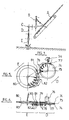
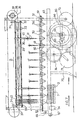
- the machine includes: - a tray holder assembly A equipped with the clod extraction device, - a set B for taking charge and transferring clods, a set C for conveying clods supplying according to the invention: - a device D for turning the plants, - a planting device E.
- the set of tray holders A, the set B for handling and transferring clods, and an embodiment of the set C for conveying are described in the aforementioned initial request.
- the conveying assembly C is, in the embodiment described below, constituted by a handling chain 50 circulating in a closed loop in a horizontal plane between two free toothed wheels 51 and driving 52, the latter being keyed on the shaft output of a hydraulic motor 54 supplied by the proportional rotary distributor 63 of the orbitrol type mounted on the main chassis of the machine and in mechanical connection with one of the carrying wheels by means of a mechanical speed variator 64.
- On the handling chain are mounted at regular intervals buckets 56 of elongated frustoconical shape, in number, over the length of the chain trajectory between the two axes of the toothed wheels, at least equal to the number of pliers, their spacing corresponding to that clamps in the maximum spacing position.
- the direction of translation of the chain is such that the buckets circulate from the rear towards the front of the machine on the part of the trajectory located below the plane of opening of the clamps and from the front towards the rear of the machine on the part of the trajectory placed above the turning and planting devices.
- the cups with an elongated pyramidal shape, with a square base, arranged point downward, consist of two half-parts, one fixed, the other movable so as to allow the opening of the cup by pivoting about an axis forming an angle. 45 ° with the direction of travel of the chain, the opening half of the bucket being that which is situated in the forward direction of travel. This opening is caused directly above the release point above the turning device D by the setting support on a fixed guide ramp 60 of a roller 61 secured to the opening half-part.
- the turning device D consists of two discs 74 made of flexible and elastic material, rubber for example, arranged on either side of a circular crown 75 whose width is very slightly greater than the diameter of the root ball. The difference in the radii of the discs and of the crown corresponds substantially to the height of the root ball.
- the disc and crown assembly is rotated using a hydraulic motor 76, the speed of which is adjusted to the running speed of the buckets, that is to say that of the hydraulic motor 54.
- one of the discs is deflected outwards upstream of the plant release point by the bucket 56, by means of a roller 77 operating on the internal edge of the disc, in order to facilitate the introduction of the root ball, the latter coming, by its base, into abutment on the periphery of the circular crown 75.
- the disc is brought back to its normal position and subjected to the action of a battery of pinch rollers 78 of radiating axes acting on the external face of the disc along a radius greater than that of the crown 75, said rollers being distributed over a portion of circular sector; opposite this is mounted a portion of circular ramp 79 on which the other disc is supported; this arrangement ensures sufficient clamping of the clods without risk of crushing during the passage of the discs between said ramp and the pressure rollers.
- the turning device is mounted on the rectangular frame constituting the secondary frame 69; on this same frame is also fixed the planting device E, which consists of two discs 80 made of flexible and elastic material such as rubber for example, mounted in contact with one another.
- At least one discs 80 is deflected outwards by means of a roller 81 placed upstream from the point of release of the root ball by the turning device, said roller operating on the internal edge of the disc; the disc is immediately returned to its normal position and undergoes the action of a battery of pinch rollers 82 with radiating axes distributed over a portion of circular sector; opposite this is mounted a portion of circular ramp 83 on which the other disc bears.
- the planting at the desired depth of the plants can be determined in a precise manner by adjusting the position of the axis of rotation of the disks 80 relative to the axis of the turning device on the one hand and relative to the soil of somewhere else.
- the circumferential speed of the planting device is equal to the speed of advance of the machine: for this purpose, the drive of the disks 80 is ensured from one of the carrying wheels of the machine by means of a shaft of transmission with cardan couplings.
- the planter device Given the small thickness of the planter device, it can fit between the press wheels 71, the action of which can thus be exercised as close as possible to the point of removal of the plant at the bottom of the furrow for close it and immobilize the plant.
- the buckets 56 can scroll transversely relative to the advancement of the machine, and deliver in a battery of turning and planting devices arranged at regular intervals in vertical planes parallel to said displacement.
- the machine according to the invention can be used for planting clod plants of all kinds.
Landscapes
- Life Sciences & Earth Sciences (AREA)
- Soil Sciences (AREA)
- Environmental Sciences (AREA)
- Transplanting Machines (AREA)
- Cultivation Receptacles Or Flower-Pots, Or Pots For Seedlings (AREA)
Applications Claiming Priority (4)
| Application Number | Priority Date | Filing Date | Title |
|---|---|---|---|
| FR8606071 | 1986-04-23 | ||
| FR8606071A FR2597702B1 (fr) | 1986-04-23 | 1986-04-23 | Nouvelle machine planteuse de plants en mottes. |
| FR8607914A FR2599211B2 (fr) | 1986-05-28 | 1986-05-28 | Nouvelle machine planteuse de plants en mottes. |
| FR8607914 | 1986-05-28 |
Related Parent Applications (2)
| Application Number | Title | Priority Date | Filing Date |
|---|---|---|---|
| EP87400919A Division EP0243264A1 (de) | 1986-04-23 | 1987-04-21 | Pflanzmaschine und Verfahren zum pflanzen für Setzlinge in Topfballen |
| EP87400919.4 Division | 1987-04-21 |
Publications (2)
| Publication Number | Publication Date |
|---|---|
| EP0396208A2 true EP0396208A2 (de) | 1990-11-07 |
| EP0396208A3 EP0396208A3 (de) | 1991-01-09 |
Family
ID=26225205
Family Applications (2)
| Application Number | Title | Priority Date | Filing Date |
|---|---|---|---|
| EP87400919A Withdrawn EP0243264A1 (de) | 1986-04-23 | 1987-04-21 | Pflanzmaschine und Verfahren zum pflanzen für Setzlinge in Topfballen |
| EP19900201525 Withdrawn EP0396208A3 (de) | 1986-04-23 | 1987-04-21 | Pflanzmaschine für Setzlinge in Topfballen |
Family Applications Before (1)
| Application Number | Title | Priority Date | Filing Date |
|---|---|---|---|
| EP87400919A Withdrawn EP0243264A1 (de) | 1986-04-23 | 1987-04-21 | Pflanzmaschine und Verfahren zum pflanzen für Setzlinge in Topfballen |
Country Status (3)
| Country | Link |
|---|---|
| EP (2) | EP0243264A1 (de) |
| AU (1) | AU7185787A (de) |
| IL (1) | IL82306A0 (de) |
Cited By (5)
| Publication number | Priority date | Publication date | Assignee | Title |
|---|---|---|---|---|
| EP0612466A1 (de) * | 1993-02-26 | 1994-08-31 | REGERO, Société Anonyme dite: | Module um Pflanzensetzlinge aus einen Behälter mit Aufnahmen zu Pflanzen |
| EP0653907A4 (de) * | 1992-08-10 | 1995-07-19 | Williames Hi Tech Int | Automatische pflanzmaschine topfballen aus einer saatkiste nehmend. |
| EP0712569A1 (de) * | 1994-11-17 | 1996-05-22 | YANMAR AGRICULTURAL EQUIPMENT Co., Ltd. | Pflanzmaschine |
| CN105248021A (zh) * | 2014-07-15 | 2016-01-20 | 现代农装科技股份有限公司 | 栽植装置、移栽机以及使用该栽植装置进行栽植的方法 |
| CN105580546A (zh) * | 2015-12-10 | 2016-05-18 | 河南科技大学 | 一种叶菜移栽机 |
Families Citing this family (15)
| Publication number | Priority date | Publication date | Assignee | Title |
|---|---|---|---|---|
| US4998945A (en) * | 1988-12-14 | 1991-03-12 | National Research Development Corporation | Transplanting equipment |
| EP0613614B1 (de) * | 1993-03-04 | 1999-09-08 | YANMAR AGRICULTURAL EQUIPMENT Co., Ltd. | Pflanzgerät für Setzlinge |
| WO1995004451A1 (en) * | 1993-08-04 | 1995-02-16 | Speedling, Inc. | A transplanter for seedlings |
| BE1009161A3 (nl) * | 1995-02-28 | 1996-12-03 | Den Eynde Willy Van | Machine voor het planten van stekplanten. |
| NL194775C (nl) * | 1995-03-03 | 2003-03-04 | Vries Engineering I O De | Werkwijze en inrichting voor het mechanisch in een met teelaarde gevulde houder planten van een verzameling als stortgoed aangevoerde bollen van een gewas. |
| JP3215941B2 (ja) * | 1996-05-10 | 2001-10-09 | 株式会社サークル鉄工 | 苗株搬送装置とその搬送方法 |
| NL1004688C2 (nl) * | 1996-06-03 | 1998-04-24 | Tuinbouw Tech Atelier Tta B V | Overplantinrichting, in het bijzonder een grijper en overzetsysteem daarvoor, alsmede werkwijze voor het bedrijf van de overplantinrichting. |
| CN1324937C (zh) * | 2005-09-30 | 2007-07-11 | 浙江理工大学 | 有序抛秧导苗装置 |
| CN110463422B (zh) * | 2019-08-23 | 2021-07-09 | 长江大学 | 一种芯槽式移栽机的输苗联动机构 |
| CN111527844B (zh) * | 2020-05-15 | 2025-04-15 | 黑龙江省农垦科学院 | 水稻钵苗移栽整排多株夹取式取苗机构 |
| CN112335515B (zh) * | 2020-11-06 | 2023-07-21 | 广西壮族自治区亚热带作物研究所(广西亚热带农产品加工研究所) | 一种山茶科植物幼苗移栽用批量处理装置及其使用方法 |
| CN115726178B (zh) * | 2021-08-27 | 2025-11-28 | 海尔衣联生态科技(上海)有限公司 | 用于叠衣机的装载驱动装置及叠衣机 |
| CN116034685B (zh) * | 2023-01-06 | 2025-03-11 | 上海园林绿化建设有限公司 | 一种沉水植物种植插种装置及方法 |
| CN119605424B (zh) * | 2025-02-13 | 2025-10-03 | 青岛农业大学 | 一种甘薯移栽机低损送苗装置及开合控制方法 |
| CN120113443B (zh) * | 2025-05-09 | 2025-08-29 | 山西荣辉农耕农业股份有限公司 | 一种胡萝卜播种覆膜装置及方法 |
Family Cites Families (8)
| Publication number | Priority date | Publication date | Assignee | Title |
|---|---|---|---|---|
| DE902688C (de) * | 1943-06-08 | 1954-01-25 | Heinrich Weiste | Vorrichtung zum Setzen von Pflanzen |
| DE878574C (de) * | 1951-03-30 | 1953-06-05 | Alfred Elsner | Pflanzmaschine fuer Feldgemuese- und Forstpflanzen |
| FR1062986A (fr) * | 1952-09-15 | 1954-04-28 | Machine à planter perfectionnée | |
| FR1109697A (fr) * | 1954-10-09 | 1956-01-31 | Perfectionnements aux planteuses | |
| FR1245013A (fr) * | 1959-09-25 | 1960-11-04 | Machine à repiquer les plants de riz et plants analogues | |
| US3103186A (en) * | 1960-12-06 | 1963-09-10 | James F Saifuku | Pineapple planter |
| FR2432265A1 (fr) * | 1978-08-02 | 1980-02-29 | Mametora Agricult Mach | Machine a repiquer de jeunes plants |
| US4443151A (en) * | 1980-07-09 | 1984-04-17 | Bud Antle, Inc. | Automatic soil plug loader and feeder |
-
1987
- 1987-04-21 EP EP87400919A patent/EP0243264A1/de not_active Withdrawn
- 1987-04-21 EP EP19900201525 patent/EP0396208A3/de not_active Withdrawn
- 1987-04-22 AU AU71857/87A patent/AU7185787A/en not_active Abandoned
- 1987-04-23 IL IL82306A patent/IL82306A0/xx unknown
Cited By (8)
| Publication number | Priority date | Publication date | Assignee | Title |
|---|---|---|---|---|
| EP0653907A4 (de) * | 1992-08-10 | 1995-07-19 | Williames Hi Tech Int | Automatische pflanzmaschine topfballen aus einer saatkiste nehmend. |
| EP0612466A1 (de) * | 1993-02-26 | 1994-08-31 | REGERO, Société Anonyme dite: | Module um Pflanzensetzlinge aus einen Behälter mit Aufnahmen zu Pflanzen |
| FR2701804A1 (fr) * | 1993-02-26 | 1994-09-02 | Regero Sa | Module pour planteuse de mini-mottes cultivées dans des plateaux alvéoles. |
| EP0712569A1 (de) * | 1994-11-17 | 1996-05-22 | YANMAR AGRICULTURAL EQUIPMENT Co., Ltd. | Pflanzmaschine |
| US5842306A (en) * | 1994-11-17 | 1998-12-01 | Yanmar Agricultural Equipment Co., Ltd. | Transplanter |
| CN105248021A (zh) * | 2014-07-15 | 2016-01-20 | 现代农装科技股份有限公司 | 栽植装置、移栽机以及使用该栽植装置进行栽植的方法 |
| CN105248021B (zh) * | 2014-07-15 | 2017-03-22 | 现代农装科技股份有限公司 | 栽植装置、移栽机以及使用该栽植装置进行栽植的方法 |
| CN105580546A (zh) * | 2015-12-10 | 2016-05-18 | 河南科技大学 | 一种叶菜移栽机 |
Also Published As
| Publication number | Publication date |
|---|---|
| IL82306A0 (en) | 1987-10-30 |
| AU7185787A (en) | 1987-10-29 |
| EP0243264A1 (de) | 1987-10-28 |
| EP0396208A3 (de) | 1991-01-09 |
Similar Documents
| Publication | Publication Date | Title |
|---|---|---|
| EP3813505B1 (de) | Anordnung zur ausgabe von granulatförmigen produkten | |
| EP0243264A1 (de) | Pflanzmaschine und Verfahren zum pflanzen für Setzlinge in Topfballen | |
| FR2548518A1 (fr) | Machine remorquee ou bien prevue pour l'attelage en trois points d'un tracteur pour la recolte de mais ou bien un produit analogue de moissonnage a tiges | |
| FR2569081A1 (fr) | Epandeur d'engrais | |
| FR2631208A1 (fr) | Perfectionnement aux machines agricoles avec un chassis porte-outils articule | |
| EP0153893A2 (de) | Rotierende mechanische Sämaschine, um gleichzeitig zu säen und abzudecken | |
| FR2976447A1 (fr) | Machine a tirer automatiquement les sarments de vigne tailles | |
| CN213961116U (zh) | 一种自动下苗的果树开沟栽植机 | |
| EP0609148A1 (de) | Selbstfahrendhandhabungsmaschine, insbesondere für Landwirtschaft und Gartenbau | |
| FR2647626A1 (fr) | Dispositif perfectionne d'implantation de semence dans le sol, semoir et machine combinee de preparation de lit de semence et de semis utilisant ledit dispositif | |
| EP1222845B1 (de) | Verfahren zum Trennen eckiger Setzlinge, Gerät zum Ausführen des Verfahrens und Pflanzmaschine mit einem solchen Gerät zum Pflanzen von Setzlingen | |
| FR2599211A2 (fr) | Nouvelle machine planteuse de plants en mottes. | |
| FR2471739A1 (fr) | Dispositif d'effacement mecanique pouvant etre equipe d'un element epampreur ou ebourgeonneur, ou d'un element faucheur d'herbe sous souche de vigne | |
| EP0133134A2 (de) | Drillmaschine für Saat unter Folie | |
| FR2458212A1 (fr) | Machine pour poser sur le sol une bande de matiere plastique et pour semer a travers la bande posee | |
| JP2010259398A (ja) | 葉菜収穫機 | |
| FR2801168A1 (fr) | Procede pour separer des mottes cubiques, dispositif pour la mise en oeuvre du procede et machine de plantation de plants en mottes comportant un tel dispositif | |
| EP0229805B1 (de) | Maschine zum automatischen einlegen von erzeugnissen in empfangszellen | |
| FR2577754A1 (fr) | Procede et dispositif de terrage en bout de rang pour semoir de graines sous paillage | |
| EP0402290B1 (de) | Verbesserung an einem Säsystem, Sämaschine und kombinierte Maschine zur Saatbettherrichtung und zum Säen mit einem solchen Säsystem | |
| FR2536947A1 (de) | ||
| FR2793471A1 (fr) | Machine d'emballage a retraction verticale | |
| EP0465327A2 (de) | Vorrichtung für die Errichtung von Kulturtunneln | |
| EP0770322A1 (de) | Kohlerntesystem | |
| EP0488981B1 (de) | Pflanzmaschine |
Legal Events
| Date | Code | Title | Description |
|---|---|---|---|
| PUAI | Public reference made under article 153(3) epc to a published international application that has entered the european phase |
Free format text: ORIGINAL CODE: 0009012 |
|
| AC | Divisional application: reference to earlier application |
Ref document number: 243264 Country of ref document: EP |
|
| AK | Designated contracting states |
Kind code of ref document: A2 Designated state(s): DE ES GB IT |
|
| PUAL | Search report despatched |
Free format text: ORIGINAL CODE: 0009013 |
|
| AK | Designated contracting states |
Kind code of ref document: A3 Designated state(s): DE ES GB IT |
|
| 17P | Request for examination filed |
Effective date: 19910215 |
|
| 17Q | First examination report despatched |
Effective date: 19920430 |
|
| STAA | Information on the status of an ep patent application or granted ep patent |
Free format text: STATUS: THE APPLICATION IS DEEMED TO BE WITHDRAWN |
|
| 18D | Application deemed to be withdrawn |
Effective date: 19940831 |