EP0396298A2 - Digitaler Zeichendrucker - Google Patents
Digitaler Zeichendrucker Download PDFInfo
- Publication number
- EP0396298A2 EP0396298A2 EP90304354A EP90304354A EP0396298A2 EP 0396298 A2 EP0396298 A2 EP 0396298A2 EP 90304354 A EP90304354 A EP 90304354A EP 90304354 A EP90304354 A EP 90304354A EP 0396298 A2 EP0396298 A2 EP 0396298A2
- Authority
- EP
- European Patent Office
- Prior art keywords
- driver
- printer
- racks
- main shaft
- numeral wheels
- Prior art date
- Legal status (The legal status is an assumption and is not a legal conclusion. Google has not performed a legal analysis and makes no representation as to the accuracy of the status listed.)
- Granted
Links
Images


Classifications
-
- G—PHYSICS
- G07—CHECKING-DEVICES
- G07B—TICKET-ISSUING APPARATUS; FARE-REGISTERING APPARATUS; FRANKING APPARATUS
- G07B17/00—Franking apparatus
- G07B17/00185—Details internally of apparatus in a franking system, e.g. franking machine at customer or apparatus at post office
- G07B17/00314—Communication within apparatus, personal computer [PC] system, or server, e.g. between printhead and central unit in a franking machine
-
- G—PHYSICS
- G07—CHECKING-DEVICES
- G07B—TICKET-ISSUING APPARATUS; FARE-REGISTERING APPARATUS; FRANKING APPARATUS
- G07B17/00—Franking apparatus
- G07B17/00459—Details relating to mailpieces in a franking system
- G07B17/00508—Printing or attaching on mailpieces
-
- G—PHYSICS
- G07—CHECKING-DEVICES
- G07B—TICKET-ISSUING APPARATUS; FARE-REGISTERING APPARATUS; FRANKING APPARATUS
- G07B17/00—Franking apparatus
- G07B17/00459—Details relating to mailpieces in a franking system
- G07B17/00467—Transporting mailpieces
-
- G—PHYSICS
- G07—CHECKING-DEVICES
- G07B—TICKET-ISSUING APPARATUS; FARE-REGISTERING APPARATUS; FRANKING APPARATUS
- G07B17/00—Franking apparatus
- G07B17/00459—Details relating to mailpieces in a franking system
- G07B17/00661—Sensing or measuring mailpieces
-
- G—PHYSICS
- G07—CHECKING-DEVICES
- G07B—TICKET-ISSUING APPARATUS; FARE-REGISTERING APPARATUS; FRANKING APPARATUS
- G07B17/00—Franking apparatus
- G07B17/00185—Details internally of apparatus in a franking system, e.g. franking machine at customer or apparatus at post office
- G07B17/00314—Communication within apparatus, personal computer [PC] system, or server, e.g. between printhead and central unit in a franking machine
- G07B2017/00322—Communication between components/modules/parts, e.g. printer, printhead, keyboard, conveyor or central unit
-
- G—PHYSICS
- G07—CHECKING-DEVICES
- G07B—TICKET-ISSUING APPARATUS; FARE-REGISTERING APPARATUS; FRANKING APPARATUS
- G07B17/00—Franking apparatus
- G07B17/00459—Details relating to mailpieces in a franking system
- G07B17/00508—Printing or attaching on mailpieces
- G07B2017/00516—Details of printing apparatus
- G07B2017/00524—Printheads
- G07B2017/00548—Mechanical printhead
-
- G—PHYSICS
- G07—CHECKING-DEVICES
- G07B—TICKET-ISSUING APPARATUS; FARE-REGISTERING APPARATUS; FRANKING APPARATUS
- G07B17/00—Franking apparatus
- G07B17/00459—Details relating to mailpieces in a franking system
- G07B17/00661—Sensing or measuring mailpieces
- G07B2017/00701—Measuring the weight of mailpieces
Definitions
- the present invention relates to a digital mark-printer, and more particularly relates to a printer controlled by stored program within a micro-processor system and that automatically and programmably performs the function of printing a variety of marks, such as postmarks used in the postal office.
- the setting mechanism is electricallly controlled to interface the postage printing device with a computerized or electronic postage system.
- the setting mechanism comprises a main rotatable driving gear which is slidable upon a splined shaft so as to individually, operatively engage a plurality of print wheel driving racks in a sequencial fashion.
- a setting linkage connected to the main driving gear positions the gear into individual engagement with a plurality of rotatable shafts individually driving each of the print wheel driving racks.
- a stepper motor is connected to the splined shaft, which in turn rotatably drives the main drive gear.
- the setting linkage is actuated by means of a pair of solenoids.
- a primary object of the present invention is to provide a fully automatic mark-changable printer which through control of stored program in a micro-processor system can print a date mark, cost mark, etc, with more print marks available than in the prior art.
- a further object of the present invention is to provide an electro-mechanically integrated, fully automatic digital mark-printer system which is computerized so that it can cooperate with other peripheral equipment to provide an unmanned fully automatic system for use in business.
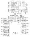
- a central processing unit (abbreviated as CPU hereinafter) 10 basically comprises a main control program 101, a microprocessor main control module 102, a display interface circuit 103 connected to a monitor 14, a printer interface circuit 105 connected to a printer 12. In practice, if necessary, it may further comprise a weighing scale interface circuit 104 connected to a weighing scale 11, an asynchronous interface circuit 106 connected to a payment system 13, a host interface circuit 107 connected to a modem 15A as well as a remote host 15, and a driver/sensor module interface circuit 108.
- the CPU 10 is electrically connected to a parallel bus interface circuit 20 through a parallel bus.
- the parallel bus interface circuit 20 comprises a sensor circuit 21 and a driver circuit 24.
- the sensor circuit 20 includes a keyboard interface circuit 22 connected to a keyboard 221 and a driver index interface circuit 23.
- the driver circuit 24 includes a first driver circuit 25, connected to a conveying driver 251 and an auxiliary driver 252, and a second driver circuit 25A.
- the second driver circuit 25A electrically connected to a main driver 256, a first wheel driver 253A, a second wheel driver 253B,... and an Nth wheel driver 253N.
- the driver index interface circuit 23 electrically connected to a first wheel driver indexer 231, a second wheel driver indexer 232, an Nth wheel driver indexer 233, etc., a main driver indexer 234, a conveying driver indexer 235 and an auxiliary driver indexer 236.
- the CPU 10 can accept instructions input from the keyboard 221 through the keyboard interface circuit 22.
- the CPU 10 calculates the proper postage based on the available data and displays it on the screen of the CRT 14.
- the customer can then pay for the postage by inserting a specially-designed card in the payment system 13 or by some other device for inserting coins, whereby the CPU 10 will actuate the first driver circuit 25 and the second driver circuit 25A through the driver circuit 24, and consequently activate the conveying driver 251 and auxiliary drier 252 to move and bring the postal material to a proper position for printing.
- the wheel drivers 253A, 253B,... 253N are also actuated and rotate their respective numerical wheels.
- the CPU 10 instructs each of the wheel drivers to rotate a certain angle in cooperation with the data from the respective wheel driver indexer 231, 232, 233, etc., until each desired number is respectively attained and then she CPU 10 activates the first driver circuit 25 and second driver circuit 25A thereby rotating the main driver 256 and postmarking and imprinting the date and postage on the postal material. Furthermore, the main driver 256 is restored to its home position for the next working cycle by sensing the main driver indexer 234.
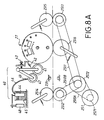
- the device includes a conveying system 250 and a postmark printing system 27 wherein the conveying system 250 is arranged above and below a conveying reference surface A1, including a main driving means of the conveying system, for example a stepper motor 251 driving a first roller 2512 and a second roller 2513 through timing belts 2510 and 2511 respectively.
- a main driving means of the conveying system for example a stepper motor 251 driving a first roller 2512 and a second roller 2513 through timing belts 2510 and 2511 respectively.
- a main driving means of the conveying system for example a stepper motor 251 driving a first roller 2512 and a second roller 2513 through timing belts 2510 and 2511 respectively.
- a main driving means of the conveying system for example a stepper motor 251 driving a first roller 2512 and a second roller 2513 through timing belts 2510 and 2511 respectively.
- a main driving means of the conveying system for example a stepper motor 251 driving a first roller 2512 and a second
- the postmark wheel means 271 further comprises a numeral wheel 2711, a gear 2712 attached therewith, a first rack 2713 engaged with the gear 2712, a guiding bar 2714 for the rack 2713 to move thereon, and a hooking arm 2715.
- the lower end of the hooking arm is secured to a recess 2506 of a second rack 2504.
- an encoder 234A and a main driver indexer 234 are disposed near the driving portion of the second stepper motor 256.
- an encoder 253A1 and a first wheel driver indexer 231 are disposed thereon.
- the printing head 27 Prior to the entering of postal material into the conveying system, the printing head 27 is zeroed to its home position (not shown) wherein a motor 251 is the prime driving source of the conveying system. As shown in Figs. 8A and 8B, disposed between the first roller 2512 and printing head 27 is a phototransistor conveying driver indexer 235 whereby after postal material 10 passes through the indexer 235, the CPU 10 will actuate the printing head 27. Below the printing head 27 is a third idle wheel 2516 with stretching spring in order that the postal material 10 be in close contact with the numeral wheel 271 of the printing head 27, as shown in Fig. 8B.
- the ink applied to the numeral wheel 271 it will be applied by a printing ink means 40, as shown in Figs. 8A and 8B.
- An ink wheel 41 is secured to a spring 42 and kept apart for a small gap from the printing head 27 by an adjusting screw 43 so that only when the protruding part of the numeral wheel passes by will the ink wheel 41 have proper contact therewith.
- the printing head 27 will, driven by a solenoid 48 and a pump 44, cause the ink wheel 41 to be provided with suitable amount of ink.
- the disclosure thus far is related only to a printing head with one numeral wheel.
- the device works with four numeral wheels, or more than four numeral wheels arranged as two or more parallel sets, wherein one set functions as date numeral wheel, and the other as postal charge numeral wheel, as shown in Figs. 2 and 3.
- Various arrangements between a plurality of stepper motors 253A - 253F and their related second racks 2504A - 2504F for each set of character wheels are shown in Figs. 5, 6 and 7, respectively.
- four stepper motors 253A - 253D are disposed within a square frame. Two sets in this arrangement will drive eight numeral wheels 271.
- ten character wheels and twelve character wheels may also be driven by a pair of five and six stepper motors arranged as illustrated in Figs. 6 and 7, respectively.
- more character wheels can be arranged as necessary.
- a relatively smaller diameter portion 2505B of the main shaft 2505 of the printing head is located near the driving gear 253A4, as shown in Fig. 4.
- the outer perimeter of the relatively smaller diameter portion 2505B comes flush with the dented base 2502 of the second rack 2504, so that after respective stepper motors 253A - 253N are located at their proper positions and the main shaft 2505 of the printing head rotates, the second racks 2504 and the relatively smaller diamter portions 2505B can dip through the driving gear 253A4.
- the second rack 2504 for driving the character wheels of the printing head 27 can slide axially along the main shaft 2505, and also can rotate together with the main shaft 2505 after reaching its proper position, thus easing the work of the printing head 27 and reducing the very complicated mechanism needed in the prior art. This is a further important advantage of the present invention.
- the numeral wheel driving means includes a stepper motor 252 and a coupler shaft 2521, the coupler shaft 2521 connecting the stepper motor 252 to a screw rod 2523 to make the screw rod 2523 rotate together with the stepper motor 252.
- a screw block 2522 is rotatably mounted on the screw rod 2523, and a solenoid seat 314 is further installed on the screw block 2522 (as shown in Fig. 10).
- Numeral wheel drivers 253A - 253N are disposed on both sides of the solenoid seat 314.
- the numeral wheel drivers are plural solenoids 253A, 253B,... 253N which can extend or retract their piston rod according to commands from CPU to engage with or disengage from the second racks 2504 for setting the corresponding numeral wheels 271A, 271B,... 271N (as shown in Figs. 9, 10 and 12).
- the numeral wheel can be driven in another manner.
- the solenoid 253A can extend its piston rod into the first dent 2502 of the second rack 2504 at the beginning, and then move together with the solenoid seat 314 to make the second rack 2504 move forward.
- the solenoid 253A moves to the original position of the second dent, it then retracts its piston rod and stays that way until the end position. Therefore, the numeral wheel 271 is driven from “1" to "2" by the second rack 2504.
- Other numerals can be achieved by a similar way.
- the solenoids 253 all retract their piston rods and the stepper motor 252 rotates counterclockwise to move the solenoid seat 314 back to the home position, whereby the solenoid 253 can urge against the projections 2503 at the end of the second racks 2504 to bring the second racks 2504 as well as all numeral wheels back to their home positions for next working cycle.
- a coaxial pulley 2573 is disposed between the pulleys 2572 and 2574, whereby through pulleys 2571, 2572, 2573 and belts 2510A, 2561, the motor 251 of the conveying means can drive the shaft 2563 of the brake clutch 2564 of the main shaft driving means 256.
- the solenoid 234 of the brake clutch 2564 (see Fig. 9) is activated to rotate the shaft 2565 of the brake clutch 2564 for one turn and stop the shaft 2565 in its original position. Accordingly, the driving gear 2566 to which the shaft 2565 connects rotates and urges another driving gear 2567 to rotate. As a result, through the shaft 2565, the printing head 27 is rotated for one turn and stopped where it was, whereby the postal material is imprinted between the printing head 27 and the idle roller 2516 disposed thereunder and carried away by conveying pulley 2513 and idle roller 2515. Then, the motor 251 of the conveying means is instructed to stop.
Landscapes
- Engineering & Computer Science (AREA)
- Physics & Mathematics (AREA)
- General Physics & Mathematics (AREA)
- Computer Security & Cryptography (AREA)
- Computer Hardware Design (AREA)
- General Engineering & Computer Science (AREA)
- Devices For Checking Fares Or Tickets At Control Points (AREA)
- Fax Reproducing Arrangements (AREA)
- Labeling Devices (AREA)
- Accessory Devices And Overall Control Thereof (AREA)
- Character Spaces And Line Spaces In Printers (AREA)
- Printers Or Recording Devices Using Electromagnetic And Radiation Means (AREA)
- Dot-Matrix Printers And Others (AREA)
- Crushing And Grinding (AREA)
- Handling Of Sheets (AREA)
- Optical Record Carriers And Manufacture Thereof (AREA)
- Digital Transmission Methods That Use Modulated Carrier Waves (AREA)
Applications Claiming Priority (2)
| Application Number | Priority Date | Filing Date | Title |
|---|---|---|---|
| US07/347,863 US5050495A (en) | 1989-05-05 | 1989-05-05 | Print wheel setting mechanism |
| US347863 | 1989-05-05 |
Publications (3)
| Publication Number | Publication Date |
|---|---|
| EP0396298A2 true EP0396298A2 (de) | 1990-11-07 |
| EP0396298A3 EP0396298A3 (de) | 1991-08-07 |
| EP0396298B1 EP0396298B1 (de) | 1995-10-04 |
Family
ID=23365608
Family Applications (1)
| Application Number | Title | Priority Date | Filing Date |
|---|---|---|---|
| EP90304354A Expired - Lifetime EP0396298B1 (de) | 1989-05-05 | 1990-04-24 | Digitaler Zeichendrucker |
Country Status (13)
| Country | Link |
|---|---|
| US (1) | US5050495A (de) |
| EP (1) | EP0396298B1 (de) |
| CN (1) | CN1055437C (de) |
| AT (1) | ATE128781T1 (de) |
| AU (1) | AU634442B2 (de) |
| CA (1) | CA2014898C (de) |
| CS (1) | CS195590A3 (de) |
| DE (1) | DE69022770T2 (de) |
| DK (1) | DK96790A (de) |
| ES (1) | ES2080112T3 (de) |
| FI (1) | FI901937A7 (de) |
| NO (1) | NO901730L (de) |
| PT (1) | PT93827A (de) |
Cited By (6)
| Publication number | Priority date | Publication date | Assignee | Title |
|---|---|---|---|---|
| EP0499725A1 (de) * | 1989-10-18 | 1992-08-26 | Pitney Bowes Inc. | Vorrichtung zur Positionssteuerung von Geräten, insbesondere einer durch Mikrocomputer kontrollierten elektronischen Frankiermaschine, der getrennte Gleichstrommotoren zur Druckrädersteuerung aufweist |
| EP0522260A3 (en) * | 1991-07-11 | 1993-11-18 | Francotyp Postalia Gmbh | Device for setting the printing wheels in franking or value stamping machines |
| ES2070733A2 (es) * | 1993-04-13 | 1995-06-01 | Investronica Sa | Sistema de numeracion automatico e informatizado para el registro de documentos. |
| EP0657853A3 (de) * | 1993-12-09 | 1995-08-30 | Pitney Bowes Inc | Adressendecoder mit Speicherwartezustandsschaltung. |
| EP0657854A3 (de) * | 1993-12-09 | 1995-08-30 | Pitney Bowes Inc | Programmierbarer Uhrenmodul für Frankiermaschinensteuerungssystem. |
| EP0737943A3 (de) * | 1995-04-14 | 1997-08-13 | Ascom Hasler Mailing Sys Ag | Frankiermaschine mit einem einzigen Motor zum Einstellen und zum Drucken |
Families Citing this family (8)
| Publication number | Priority date | Publication date | Assignee | Title |
|---|---|---|---|---|
| FR2665781B1 (fr) * | 1990-08-07 | 1993-06-11 | Alcatel Satmam | Dispositif de verrouillage de molettes d'une machine a affranchir. |
| FR2665782B1 (fr) * | 1990-08-07 | 1993-06-11 | Alcatel Satmam | Dispositif de reglage de molettes d'impression dans un machine a affranchir. |
| FR2699709B1 (fr) * | 1992-12-23 | 1995-02-10 | Neopost Ind | Machine à affranchir électronique à deux tambours d'impression de données fixes et variables. |
| US5493967A (en) * | 1994-09-16 | 1996-02-27 | Pitney Bowes Inc. | Value selection and printing apparatus including a security device |
| US5445074A (en) * | 1994-11-02 | 1995-08-29 | Pitney Bowes Inc. | Value selection and printing apparatus including a security device |
| DE102008037792A1 (de) * | 2008-08-14 | 2010-02-18 | Giesecke & Devrient Gmbh | Vorrichtung und ein Verfahren zum Einrichten und Justieren von Trägerscheiben und Nummerierwerken einer Nummeriermaschine |
| CN102180028B (zh) * | 2011-01-26 | 2013-04-03 | 合肥海闻机器人开发有限公司 | 一种专用于亚克力的打印机平移器 |
| CN102909943B (zh) * | 2012-10-17 | 2014-11-26 | 西安理工大学 | 全自动机械式条形码变码印刷装置及条形码变码印刷方法 |
Family Cites Families (18)
| Publication number | Priority date | Publication date | Assignee | Title |
|---|---|---|---|---|
| US1185667A (en) * | 1916-06-06 | Robert Hoe | Inking mechanism. | |
| US4034669A (en) * | 1974-06-05 | 1977-07-12 | Pitney-Bowes, Inc. | Postage meter setting mechanism |
| US3965815A (en) * | 1974-09-16 | 1976-06-29 | Pitney-Bowes, Inc. | Setting mechanism for a postage printing device |
| GB1509111A (en) * | 1975-01-23 | 1978-04-26 | Pitney Bowes Inc | Apparatus for supplying fluent material |
| US4629871A (en) * | 1979-12-28 | 1986-12-16 | Pitney Bowes, Inc. | Electronic postage meter system settable by means of a remotely generated input device |
| DE3111953C2 (de) * | 1981-03-23 | 1983-01-13 | Francotyp Gmbh, 1000 Berlin | Einstellvorrichtung für die Druckrollen einer elektronisch gesteuerten Frankiermaschine |
| DE3111949C2 (de) * | 1981-03-23 | 1985-06-20 | Francotyp - Postalia GmbH, 1000 Berlin | Einstellvorrichtung für Frankier- und Wertstempelmaschinen |
| EP0073132A3 (de) * | 1981-08-17 | 1985-08-28 | Mccorquodale Machine Systems Limited | Registerhaltiges Drucken von Bogen |
| CH663848A5 (de) * | 1982-10-04 | 1988-01-15 | Frama Ag | Einstelleinrichtung fuer typenraeder. |
| US4595984A (en) * | 1982-10-22 | 1986-06-17 | Pitney Bowes Inc. | Apparatus and method for determining special postage fees |
| US4603627A (en) * | 1984-03-23 | 1986-08-05 | Pitney Bowes Inc. | Rotary shutter device for a postal mailing system |
| US4608923A (en) * | 1984-10-04 | 1986-09-02 | Pitney Bowes Inc. | Postal meter value selector sequencing system |
| US4604950A (en) * | 1984-10-04 | 1986-08-12 | Pitney Bowes Inc. | Worm gear rack movement system |
| GB2166389B (en) * | 1984-10-04 | 1988-10-26 | Pitney Bowes Inc | Electronic postage meter print wheel setting optimization system |
| US4580493A (en) * | 1984-10-04 | 1986-04-08 | Pitney Bowes Inc. | Helical nut-pinion-rack gear system |
| US4636959A (en) * | 1984-10-04 | 1987-01-13 | Pitney Bowes Inc. | Microprocessor controlled d.c. motor for controlling a postage meter |
| GB2177656B (en) * | 1985-07-04 | 1989-04-05 | Roneo Alcatel Ltd | Value selection mechanism for postal franking machines |
| US4933616A (en) * | 1987-08-19 | 1990-06-12 | Pitney Bowes Inc. | Drive control system for imprinting apparatus |
-
1989
- 1989-05-05 US US07/347,863 patent/US5050495A/en not_active Expired - Lifetime
-
1990
- 1990-04-18 FI FI901937A patent/FI901937A7/fi not_active IP Right Cessation
- 1990-04-18 DK DK096790A patent/DK96790A/da not_active Application Discontinuation
- 1990-04-19 NO NO90901730A patent/NO901730L/no unknown
- 1990-04-19 CS CS901955A patent/CS195590A3/cs unknown
- 1990-04-19 CA CA002014898A patent/CA2014898C/en not_active Expired - Fee Related
- 1990-04-19 CN CN90102320A patent/CN1055437C/zh not_active Expired - Fee Related
- 1990-04-20 PT PT93827A patent/PT93827A/pt not_active Application Discontinuation
- 1990-04-24 DE DE69022770T patent/DE69022770T2/de not_active Expired - Fee Related
- 1990-04-24 AT AT90304354T patent/ATE128781T1/de active
- 1990-04-24 EP EP90304354A patent/EP0396298B1/de not_active Expired - Lifetime
- 1990-04-24 ES ES90304354T patent/ES2080112T3/es not_active Expired - Lifetime
- 1990-05-07 AU AU54765/90A patent/AU634442B2/en not_active Ceased
Cited By (6)
| Publication number | Priority date | Publication date | Assignee | Title |
|---|---|---|---|---|
| EP0499725A1 (de) * | 1989-10-18 | 1992-08-26 | Pitney Bowes Inc. | Vorrichtung zur Positionssteuerung von Geräten, insbesondere einer durch Mikrocomputer kontrollierten elektronischen Frankiermaschine, der getrennte Gleichstrommotoren zur Druckrädersteuerung aufweist |
| EP0522260A3 (en) * | 1991-07-11 | 1993-11-18 | Francotyp Postalia Gmbh | Device for setting the printing wheels in franking or value stamping machines |
| ES2070733A2 (es) * | 1993-04-13 | 1995-06-01 | Investronica Sa | Sistema de numeracion automatico e informatizado para el registro de documentos. |
| EP0657853A3 (de) * | 1993-12-09 | 1995-08-30 | Pitney Bowes Inc | Adressendecoder mit Speicherwartezustandsschaltung. |
| EP0657854A3 (de) * | 1993-12-09 | 1995-08-30 | Pitney Bowes Inc | Programmierbarer Uhrenmodul für Frankiermaschinensteuerungssystem. |
| EP0737943A3 (de) * | 1995-04-14 | 1997-08-13 | Ascom Hasler Mailing Sys Ag | Frankiermaschine mit einem einzigen Motor zum Einstellen und zum Drucken |
Also Published As
| Publication number | Publication date |
|---|---|
| FI901937A7 (fi) | 1990-11-06 |
| AU634442B2 (en) | 1993-02-18 |
| EP0396298A3 (de) | 1991-08-07 |
| PT93827A (pt) | 1992-01-31 |
| DE69022770D1 (de) | 1995-11-09 |
| CN1046871A (zh) | 1990-11-14 |
| DK96790D0 (da) | 1990-04-18 |
| AU5476590A (en) | 1990-11-08 |
| FI901937A0 (fi) | 1990-04-18 |
| CS195590A3 (en) | 1992-12-16 |
| DE69022770T2 (de) | 1996-03-14 |
| ATE128781T1 (de) | 1995-10-15 |
| CA2014898C (en) | 2001-02-13 |
| ES2080112T3 (es) | 1996-02-01 |
| DK96790A (da) | 1990-11-06 |
| EP0396298B1 (de) | 1995-10-04 |
| NO901730D0 (no) | 1990-04-19 |
| CA2014898A1 (en) | 1990-11-05 |
| NO901730L (no) | 1990-11-06 |
| CN1055437C (zh) | 2000-08-16 |
| US5050495A (en) | 1991-09-24 |
Similar Documents
| Publication | Publication Date | Title |
|---|---|---|
| US5050495A (en) | Print wheel setting mechanism | |
| US5313404A (en) | Automatic postal teller machine | |
| US4568950A (en) | Postage meter-thermal tape pressure and drive control printer | |
| CA2162508C (en) | Apparatus and method for detecting the position of envelopes in a mailing machine | |
| US4547780A (en) | Printer with manual paper feed and weigh scale incorporating the same | |
| DE3685590T2 (de) | Automatische postbehandlungsvorrichtung. | |
| EP0300245B1 (de) | Steuerpultanordnung für Druckvorrichtung | |
| DE69422549T2 (de) | Etikettendrucker | |
| JPH08511736A (ja) | グラフィックスプリンタのローラ搬送装置及び方法 | |
| US4519048A (en) | Postage meter system for communicating platen movement to a microprocessor to signal completion of printing | |
| US4581616A (en) | Postage meter thermal printer tape drive system | |
| EP0800926A1 (de) | Vorrichtung und Verfahren zur Durchführung einer Bearbeitungsfunktion mit einer verzehrbaren Materialbahn | |
| EP0111314A2 (de) | Postbearbeitende Maschine und Briefumschlagauswurfsmechanismus für eine solche Maschine | |
| US3718244A (en) | Apparatus for reading pre-programmed cards and printing thereon | |
| DE69507763T2 (de) | Farbdrucker | |
| IE901367A1 (en) | A digital mark-printer | |
| US4588996A (en) | Thermal ribbon cartridge transport in a postage meter thermal printer | |
| US4605937A (en) | Postal meter thermal printer control | |
| EP0647530A2 (de) | Drucker mit auswechselbaren Druckköpfen | |
| EP0165601A2 (de) | Wärmedrucker und Frankiermaschine mit einem solchen Wärmedrucker | |
| CH653159A5 (de) | Elektronisch gesteuerte frankiermaschine. | |
| CN217863429U (zh) | 一种应用于卡片制备的印字机构 | |
| US4796526A (en) | Value printing die protection device in an electronic postage meter machine | |
| EP0111320A2 (de) | Post bearbeitende Maschine mit Datumsüberwachungsvorrichtung und Verfahren zur Warnung des Bedienungspersonals | |
| GB2142876A (en) | Stamping set |
Legal Events
| Date | Code | Title | Description |
|---|---|---|---|
| PUAI | Public reference made under article 153(3) epc to a published international application that has entered the european phase |
Free format text: ORIGINAL CODE: 0009012 |
|
| AK | Designated contracting states |
Kind code of ref document: A2 Designated state(s): AT BE CH DE ES FR GB GR IT LI LU NL SE |
|
| PUAL | Search report despatched |
Free format text: ORIGINAL CODE: 0009013 |
|
| AK | Designated contracting states |
Kind code of ref document: A3 Designated state(s): AT BE CH DE ES FR GB GR IT LI LU NL SE |
|
| 17P | Request for examination filed |
Effective date: 19920205 |
|
| 17Q | First examination report despatched |
Effective date: 19930804 |
|
| GRAA | (expected) grant |
Free format text: ORIGINAL CODE: 0009210 |
|
| AK | Designated contracting states |
Kind code of ref document: B1 Designated state(s): AT BE CH DE ES FR GB GR IT LI LU NL SE |
|
| PG25 | Lapsed in a contracting state [announced via postgrant information from national office to epo] |
Ref country code: NL Free format text: LAPSE BECAUSE OF FAILURE TO SUBMIT A TRANSLATION OF THE DESCRIPTION OR TO PAY THE FEE WITHIN THE PRESCRIBED TIME-LIMIT Effective date: 19951004 Ref country code: GR Free format text: LAPSE BECAUSE OF FAILURE TO SUBMIT A TRANSLATION OF THE DESCRIPTION OR TO PAY THE FEE WITHIN THE PRESCRIBED TIME-LIMIT Effective date: 19951004 Ref country code: BE Effective date: 19951004 Ref country code: AT Effective date: 19951004 |
|
| REF | Corresponds to: |
Ref document number: 128781 Country of ref document: AT Date of ref document: 19951015 Kind code of ref document: T |
|
| REF | Corresponds to: |
Ref document number: 69022770 Country of ref document: DE Date of ref document: 19951109 |
|
| ITF | It: translation for a ep patent filed | ||
| PG25 | Lapsed in a contracting state [announced via postgrant information from national office to epo] |
Ref country code: SE Effective date: 19960104 |
|
| REG | Reference to a national code |
Ref country code: ES Ref legal event code: FG2A Ref document number: 2080112 Country of ref document: ES Kind code of ref document: T3 |
|
| ET | Fr: translation filed | ||
| NLV1 | Nl: lapsed or annulled due to failure to fulfill the requirements of art. 29p and 29m of the patents act | ||
| PG25 | Lapsed in a contracting state [announced via postgrant information from national office to epo] |
Ref country code: ES Free format text: LAPSE BECAUSE OF NON-PAYMENT OF DUE FEES Effective date: 19960425 |
|
| PG25 | Lapsed in a contracting state [announced via postgrant information from national office to epo] |
Ref country code: LU Free format text: LAPSE BECAUSE OF NON-PAYMENT OF DUE FEES Effective date: 19960430 Ref country code: LI Effective date: 19960430 Ref country code: CH Effective date: 19960430 |
|
| PLBE | No opposition filed within time limit |
Free format text: ORIGINAL CODE: 0009261 |
|
| STAA | Information on the status of an ep patent application or granted ep patent |
Free format text: STATUS: NO OPPOSITION FILED WITHIN TIME LIMIT |
|
| 26N | No opposition filed | ||
| REG | Reference to a national code |
Ref country code: CH Ref legal event code: PL |
|
| REG | Reference to a national code |
Ref country code: GB Ref legal event code: IF02 |
|
| REG | Reference to a national code |
Ref country code: ES Ref legal event code: FD2A Effective date: 20030303 |
|
| PGFP | Annual fee paid to national office [announced via postgrant information from national office to epo] |
Ref country code: FR Payment date: 20040430 Year of fee payment: 15 |
|
| PGFP | Annual fee paid to national office [announced via postgrant information from national office to epo] |
Ref country code: DE Payment date: 20040618 Year of fee payment: 15 |
|
| PG25 | Lapsed in a contracting state [announced via postgrant information from national office to epo] |
Ref country code: IT Free format text: LAPSE BECAUSE OF NON-PAYMENT OF DUE FEES Effective date: 20050424 |
|
| PGFP | Annual fee paid to national office [announced via postgrant information from national office to epo] |
Ref country code: GB Payment date: 20050426 Year of fee payment: 16 |
|
| PG25 | Lapsed in a contracting state [announced via postgrant information from national office to epo] |
Ref country code: DE Free format text: LAPSE BECAUSE OF NON-PAYMENT OF DUE FEES Effective date: 20051101 |
|
| PG25 | Lapsed in a contracting state [announced via postgrant information from national office to epo] |
Ref country code: FR Free format text: LAPSE BECAUSE OF NON-PAYMENT OF DUE FEES Effective date: 20051230 |
|
| REG | Reference to a national code |
Ref country code: FR Ref legal event code: ST Effective date: 20051230 |
|
| PG25 | Lapsed in a contracting state [announced via postgrant information from national office to epo] |
Ref country code: GB Free format text: LAPSE BECAUSE OF NON-PAYMENT OF DUE FEES Effective date: 20060424 |
|
| GBPC | Gb: european patent ceased through non-payment of renewal fee |
Effective date: 20060424 |