EP0396430A2 - Réseau radiofréquence - Google Patents
Réseau radiofréquence Download PDFInfo
- Publication number
- EP0396430A2 EP0396430A2 EP90304909A EP90304909A EP0396430A2 EP 0396430 A2 EP0396430 A2 EP 0396430A2 EP 90304909 A EP90304909 A EP 90304909A EP 90304909 A EP90304909 A EP 90304909A EP 0396430 A2 EP0396430 A2 EP 0396430A2
- Authority
- EP
- European Patent Office
- Prior art keywords
- branch
- node
- input
- common
- radio frequency
- Prior art date
- Legal status (The legal status is an assumption and is not a legal conclusion. Google has not performed a legal analysis and makes no representation as to the accuracy of the status listed.)
- Withdrawn
Links
Images


Classifications
-
- H—ELECTRICITY
- H01—ELECTRIC ELEMENTS
- H01P—WAVEGUIDES; RESONATORS, LINES, OR OTHER DEVICES OF THE WAVEGUIDE TYPE
- H01P5/00—Coupling devices of the waveguide type
- H01P5/12—Coupling devices having more than two ports
- H01P5/16—Conjugate devices, i.e. devices having at least one port decoupled from one other port
Definitions
- This invention relates to a radio frequency network usable for splitting an r.f. signal or for combining a plurality of r.f. signals.
- a particular application for a combiner is in transmitters, for example television transmitters.
- a television transmitter uses a klystron in the r.f output stage to amplify the signal to be passed to the antenna. While klystrons generally perform this function satisfactorily and reliably, they require complex cooling arrangements, usually employing circulating water, and these require regular maintenance. In addition, failure of the klystron renders the transmitter inoperative.
- the present invention provides a radio frequency network, comprising a first common node connected to a common input or output port, a second common node, and at least three identical branches therebetween, each branch comprising a first branch node, to which is connected a balance load, and a second branch node spaced therefrom and connected to a branch output or input port, the network being dimensioned and arranged such that an r.f. signal of a specific frequency input at the common input port is divided equally between all the branch output ports, and a plurality of identical r.f. signals of the specific frequency applied in phase to all the branch input ports appear combined at the common output port.
- All the inter-nodal distances are preferably equal to one quarter of the operating wavelength of the input signal or signals.
- a narrow network bandwidth is unsatisfactory. It has been found that the values of the impedances of the portions of the branches between the second common nodes and each first branch node have some influence on the bandwidth of the network. By selection of suitable impedances for these portions, the bandwidth may be increased.
- the impedance is preferably low relative to the other portions of the network.
- a greater increase in bandwidth may be achieved by providing a quarter wavelength transformer between the first common node and the common input/output port, the length of the line added being a quarter of the wavelength at the centre of the bandwidth. Still further improvement of the bandwidth may be obtained by connecting to the first common node a short circuited stub, preferably having a length equal to a quarter wavelength.
- a twenty way combiner with a bandwidth of 88 to 108 MHz for an input VSWR of less than 1.02:1 can be achieved.
- the network of the invention may be formed of coaxial cable, multi-wire cable, waveguide, or even LC circuits to give a 90° phase shift.
- the quarter wavelength lines may conveniently be any odd multiple of quarter wavelengths where this makes the network physically easier to realise.
- the use of greater lengths carries the disadvantage, however, that the operating bandwidth becomes narrower.
- the network comprises sixteen identical branches 1a to 1p extending between a first common node 2 and a second common node 3.
- Each branch 1 comprises three equal lengths of coaxial cable joined at a first branch node 4 and at a second branch node 5.
- a balance load 6 is connected to the first branch node 4, while a branch input port 7 is connected to the second branch node 5.
- the inter-nodal length is in each case one quarter of the wavelength at the centre of the operating bandwidth for the network, thus giving a 90° phase shift in each portion of the network for that wavelength.
- the first common node 2 is connected to an output port 8.
- sixteen identical r.f. signals are applied in phase to the branch input ports 7a to 7p.
- the signal appearing at the output port 8 is substantially the sum of the input signals.
- the bandwidth of the network may be increased by connecting a quarter wavelength transformer 9 between the first common node 2 of the network illustrated in Figure 1, and the output port 8.
- a further improvement may be achieved by connecting a short circuited quarter wavelength stub 10 to the first common node 2.
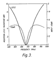
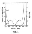
- Adjustment of the impedances of the lines extending between the second common node 3 and each of the first branch nodes 4a to 4p can also improve the bandwidth. The effects of these modifications are illustrated by Figures 3, 4 and 5.
- Figure 3 illustrates insertion loss and input VSWR against frequency for the network illustrated in Figure 1, where, in each branch, the impedance of the line from the second common node 3 to the first branch node 4 is 280 ohms, the impedance of the line between the two branch nodes 4 and 5 is 50 ohms, and the impedance of the third line is 12.5 ohms. It will be seen that, moving away from the central frequency of approximately 670 MHz, one encounters rapidly increasing loss and VSWR.
- Figure 4 shows the effect of a circuit in accordance with Figure 2, but without the short circuited stub.
- the impedances are set in each branch, from the second common node 3 to the first common node 2 as 5 ohms, 50 ohms and 100 ohms respectively.
- the quarter wavelength transformer has an impedance of 25 ohms. It will be seen that the bandwidth over which very low loss is experienced is very much greater, extending from about 470 MHz to about 860 MHz the VSWR over this range is also substantially reduced.
- Figure 5 shows the effect of adding a short-circuit stub, having an impedance of 49 ohms.
- the impedance of the line in each branch extending from the second common node to the first branch node is increased to 50 ohms, with all other impedances remaining the same. It will be seen that, while the loss is very slightly increased over the bandwidth of 470 to 860 MHz, the VSWR is significantly reduced further.
- the network of the application although particularly described with reference to television transmitters, will find application in many other types of transmitter, and generally where a plurality of r.f. signals are to be combined together or produced from a single such signal.
Landscapes
- Microwave Amplifiers (AREA)
- Amplifiers (AREA)
- Transmitters (AREA)
Applications Claiming Priority (2)
| Application Number | Priority Date | Filing Date | Title |
|---|---|---|---|
| GB8910410A GB2232028B (en) | 1989-05-05 | 1989-05-05 | Radio frequency network |
| GB8910410 | 1989-05-05 |
Publications (2)
| Publication Number | Publication Date |
|---|---|
| EP0396430A2 true EP0396430A2 (fr) | 1990-11-07 |
| EP0396430A3 EP0396430A3 (fr) | 1992-02-05 |
Family
ID=10656307
Family Applications (1)
| Application Number | Title | Priority Date | Filing Date |
|---|---|---|---|
| EP19900304909 Withdrawn EP0396430A3 (fr) | 1989-05-05 | 1990-05-04 | Réseau radiofréquence |
Country Status (5)
| Country | Link |
|---|---|
| EP (1) | EP0396430A3 (fr) |
| JP (1) | JPH0388402A (fr) |
| AU (1) | AU625827B2 (fr) |
| CA (1) | CA2015945A1 (fr) |
| GB (1) | GB2232028B (fr) |
Cited By (2)
| Publication number | Priority date | Publication date | Assignee | Title |
|---|---|---|---|---|
| EP0508662A3 (en) * | 1991-04-11 | 1993-04-14 | Harris Corporation | N-way power combiner/divider |
| WO2001061780A1 (fr) * | 2000-02-16 | 2001-08-23 | Signal Technology Corporation | Circuit combineur d'emission de puissance f.r. |
Families Citing this family (1)
| Publication number | Priority date | Publication date | Assignee | Title |
|---|---|---|---|---|
| US5223809A (en) | 1992-04-24 | 1993-06-29 | At&T Bell Laboratories | Signal isolating microwave splitters/combiners |
Family Cites Families (4)
| Publication number | Priority date | Publication date | Assignee | Title |
|---|---|---|---|---|
| US4156212A (en) * | 1977-12-19 | 1979-05-22 | Nautical Electronic Laboratories, Ltd. | Combiner system |
| US4163955A (en) * | 1978-01-16 | 1979-08-07 | International Telephone And Telegraph Corporation | Cylindrical mode power divider/combiner with isolation |
| GB2069244A (en) * | 1980-02-11 | 1981-08-19 | Decca Ltd | Radio frequency zero phase power combiner |
| DE8816832U1 (de) * | 1988-04-30 | 1990-09-20 | Grundig E.M.V. Elektro-Mechanische Versuchsanstalt Max Grundig holländ. Stiftung & Co KG, 8510 Fürth | Hybrid-Leistungsteiler, insbesondere dreitoriger Hybrid |
-
1989
- 1989-05-05 GB GB8910410A patent/GB2232028B/en not_active Expired - Lifetime
-
1990
- 1990-05-02 CA CA 2015945 patent/CA2015945A1/fr not_active Abandoned
- 1990-05-04 EP EP19900304909 patent/EP0396430A3/fr not_active Withdrawn
- 1990-05-04 AU AU54675/90A patent/AU625827B2/en not_active Ceased
- 1990-05-07 JP JP11733090A patent/JPH0388402A/ja active Pending
Cited By (2)
| Publication number | Priority date | Publication date | Assignee | Title |
|---|---|---|---|---|
| EP0508662A3 (en) * | 1991-04-11 | 1993-04-14 | Harris Corporation | N-way power combiner/divider |
| WO2001061780A1 (fr) * | 2000-02-16 | 2001-08-23 | Signal Technology Corporation | Circuit combineur d'emission de puissance f.r. |
Also Published As
| Publication number | Publication date |
|---|---|
| GB2232028B (en) | 1992-12-09 |
| AU5467590A (en) | 1990-11-08 |
| JPH0388402A (ja) | 1991-04-12 |
| GB8910410D0 (en) | 1989-06-21 |
| GB2232028A (en) | 1990-11-28 |
| CA2015945A1 (fr) | 1990-11-05 |
| AU625827B2 (en) | 1992-07-16 |
| EP0396430A3 (fr) | 1992-02-05 |
Similar Documents
| Publication | Publication Date | Title |
|---|---|---|
| US6518856B1 (en) | RF power divider/combiner circuit | |
| US5162756A (en) | High frequency transmission line circuit | |
| CA2065199C (fr) | Diviseur-combinateur polyphase | |
| FI124916B (fi) | Piiri Doherty-vahvistimien rinnankäyttöä varten | |
| US4701716A (en) | Parallel distributed signal amplifiers | |
| US4916410A (en) | Hybrid-balun for splitting/combining RF power | |
| US5789996A (en) | N-way RF power combiner/divider | |
| US7595688B2 (en) | High power commutating multiple output amplifier system | |
| US5025225A (en) | Amplifier having substantially constant D.C. to r.f. conversion efficiency | |
| US5017886A (en) | RF power combiner using baluns | |
| US3518695A (en) | Antenna array multifrequency and beam steering control multiplex feed | |
| US5313174A (en) | 2:1 bandwidth, 4-way, combiner/splitter | |
| US6078227A (en) | Dual quadrature branchline in-phase power combiner and power splitter | |
| JPH06224605A (ja) | Rf電力増幅器用の結合器 | |
| US4543545A (en) | Microwave radio frequency power divider/combiner | |
| US5966059A (en) | Phase shifting power coupler with three signals of equal amplitude | |
| US3480885A (en) | High power microwave switch | |
| US4451832A (en) | Radio frequency transmitter coupling circuit | |
| US5285175A (en) | Tri-phase combiner/splitter system | |
| EP1425851A1 (fr) | Systeme amplificateur large bande a linearite amelioree et perte minimale | |
| US5028880A (en) | Microwave power amplifier using phase inverters | |
| EP0396430A2 (fr) | Réseau radiofréquence | |
| US6118353A (en) | Microwave power divider/combiner having compact structure and flat coupling | |
| US5796317A (en) | Variable impedance transmission line and high-power broadband reduced-size power divider/combiner employing same | |
| US20140035652A1 (en) | Signal directing means for dividing an input signal into at least two output signals or combining at least two input signals into one output signal |
Legal Events
| Date | Code | Title | Description |
|---|---|---|---|
| PUAI | Public reference made under article 153(3) epc to a published international application that has entered the european phase |
Free format text: ORIGINAL CODE: 0009012 |
|
| AK | Designated contracting states |
Kind code of ref document: A2 Designated state(s): AT BE CH DE DK ES FR GR IT LI LU NL SE |
|
| PUAL | Search report despatched |
Free format text: ORIGINAL CODE: 0009013 |
|
| AK | Designated contracting states |
Kind code of ref document: A3 Designated state(s): AT BE CH DE DK ES FR GR IT LI LU NL SE |
|
| STAA | Information on the status of an ep patent application or granted ep patent |
Free format text: STATUS: THE APPLICATION IS DEEMED TO BE WITHDRAWN |
|
| 18D | Application deemed to be withdrawn |
Effective date: 19920806 |