EP0396441A1 - Drehrichtungsunabhängige kontaktlose Gleitringdichtung - Google Patents
Drehrichtungsunabhängige kontaktlose Gleitringdichtung Download PDFInfo
- Publication number
- EP0396441A1 EP0396441A1 EP90400986A EP90400986A EP0396441A1 EP 0396441 A1 EP0396441 A1 EP 0396441A1 EP 90400986 A EP90400986 A EP 90400986A EP 90400986 A EP90400986 A EP 90400986A EP 0396441 A1 EP0396441 A1 EP 0396441A1
- Authority
- EP
- European Patent Office
- Prior art keywords
- sealing
- stator
- seal
- rotor
- face
- Prior art date
- Legal status (The legal status is an assumption and is not a legal conclusion. Google has not performed a legal analysis and makes no representation as to the accuracy of the status listed.)
- Granted
Links
Images




Classifications
-
- F—MECHANICAL ENGINEERING; LIGHTING; HEATING; WEAPONS; BLASTING
- F16—ENGINEERING ELEMENTS AND UNITS; GENERAL MEASURES FOR PRODUCING AND MAINTAINING EFFECTIVE FUNCTIONING OF MACHINES OR INSTALLATIONS; THERMAL INSULATION IN GENERAL
- F16J—PISTONS; CYLINDERS; SEALINGS
- F16J15/00—Sealings
- F16J15/16—Sealings between relatively-moving surfaces
- F16J15/34—Sealings between relatively-moving surfaces with slip-ring pressed against a more or less radial face on one member
- F16J15/3404—Sealings between relatively-moving surfaces with slip-ring pressed against a more or less radial face on one member and characterised by parts or details relating to lubrication, cooling or venting of the seal
- F16J15/3408—Sealings between relatively-moving surfaces with slip-ring pressed against a more or less radial face on one member and characterised by parts or details relating to lubrication, cooling or venting of the seal at least one ring having an uneven slipping surface
- F16J15/3412—Sealings between relatively-moving surfaces with slip-ring pressed against a more or less radial face on one member and characterised by parts or details relating to lubrication, cooling or venting of the seal at least one ring having an uneven slipping surface with cavities
Definitions
- the present invention relates to a bi-directional, non-contact face seal for sealing, from the ambient, a pressurized fluid in the interior of a housing fitted with a rotatable shaft.
- non-contact seals having a gap formed between the rotor and the stator to thereby eliminate rubbing.
- Such non-contact seals represent a small percentage of conventional seals.
- the state-of-the-art conventional non-contact seals have limited application and value.
- Conventional non-contact seals generally utilize spiral type grooves in the face of the rotor.
- An example of such seal is described in U.S. Patent No. 4,212,475 to Sedy entitled Self Aligning Spiral Groove Face Seal.
- These non-contact seals are designed to function in a unidirectional manner. If the seals are driven in the opposite direction, they will not separate but will be pulled or sucked toward each other, thereby increasing wear and ultimately destroying the seal. For these reasons, the non-contact seals employing spiral grooves have significant limitations.
- Another object is to provide a seal which offers the necessary characteristics for high performance and general purpose containment of gases and liquids of poor lubrication characteristics, such as freon, air and hot water.
- Yet another object is to provide a bi-directional, non-contact face seal which allows for extremely good control over leakage while maintaining the frictional power consumption at negligible levels.
- Still another object is to provide a bi-directional, non-contact face seal which includes a rotor and stator which are split into two segments for easy around-the-shaft replacement.
- the invention comprises a bi-directional seal for sealing, from the ambient, a pressurized fluid in the interior of a housing fitted with a rotatable shaft, the seal comprising a rotor fixed and sealed against the shaft for rotation with the shaft, said rotor including a first annular sealing face substantially perpendicular to the shaft; a stator axially slidably held relative to the housing for movement toward and away from the rotor, the stator including a second annular sealing face substantially perpendicular to the shaft; the first and second annular sealing faces being aligned with and opposed to each other, a variable gap between said faces providing a channel for the pressurized fluid to flow toward the ambient; means for preventing the rotation of the stator relative to the housing; sealing means for substantially preventing the flow of pressurized fluid to the ambient in areas other than across the sealing faces; means for biasing the stator and its second annular sealing face
- the gap positioning means includes a plurality of radial grooves formed in one of the first and second sealing faces and positioned for fluid communication with the pressurized fluid.
- the radial grooves extend inwardly from the outer periphery of the sealing face in which they are formed a radial distance less than the radial span of the respective sealing face. The remaining portion of the sealing face provides a sealing dam radially downstream to the radial grooves.
- the plurality of radial grooves are spaced from one another so that a plurality of lands separate the plurality of radial grooves.
- the ratio of the distance between the ungrooved sealing faces over the distance between the bottom of the radial grooves and the opposite sealing face is within the range of 0.1 to 0.3.
- a bi-directional seal for sealing, from the ambient, a pressurized fluid in the interior of a housing fitted with a rotatable shaft.
- the bi-directional, non-contact seal 20 of the present invention serves to provide a seal between a high pressure environment located at one side of a rotating shaft 22 and a low pressure or ambient environment located at the other side of shaft 22.
- the high pressure environment shown in Fig. 1, is enclosed within a machine housing 24 and located to the exterior of shaft 22 and seal 20.
- An ambient pressure environment is located to the left of the machine housing 24 and along the outside diameter 23 of shaft 22 proximate seal 20.
- a rotor is fixed and sealed against the shaft for rotation with the shaft, and the rotor includes a first annular sealing face substantially perpendicular to the shaft.
- seal 20 includes a circumferential rotor 26 having a sealing face 38. The rotor 26 is fixed to machine shaft 22 by a rotor carrier 28.
- a stator is axially slidably held relative to the housing for movement toward and away from the rotor, and the stator includes a second annular sealing face substantially perpendicular to the shaft.
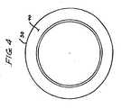
- stator 30 includes a rear portion 32 having top and bottom surfaces, 32a and 32b, respectively, and a sealing face 40 located opposite of the rear portion 32.
- Stator 30 is housed within a U-shaped cup 34 affixed and sealed against housing 24 by conventional means.
- Cup 34 forms an elongated cup recess 36 having top, bottom and rear walls 36a, 36b and 36c, respectively, into which the rear portion 32 of stator 30 is slidably received for axial movement in response to force imparted thereon.
- Top surface 32a can slide along top wall 36a and bottom surface 32b can ride along the bottom wall 36b of cup recess 36.
- a recess 46 may be formed along bottom surface 32b of rear portion 32. As a result, bottom surface 32b may be shorter in length than top surface 32a of stator 30.
- cup 34 is made from metal
- stator 30 is made of a carbon/graphite seal ring
- rotor 26 is made of a hard wear resistant material such as silicon carbide.
- the first and second sealing faces are aligned with and opposed to each other a predetermined operating distance defining a gap, the gap providing a channel for the pressurized fluid to flow toward the ambient.
- rotor 26 and stator 30 are aligned with and opposed to each other so that an operating distance referred to as gap A is located at their interface.
- rotor 26 includes a circumferential rotor sealing face 38 which is substantially perpendicular to the axis of shaft 22.
- stator 30 includes an annular stator sealing face 40.
- stator rotation prevention means includes an anti-rotational lug 42 that may be attached to or made integral with cup 34. Lug 42 cooperates with one or more slots formed in stator 30 to prevent stator 30 from rotating relative to cup 34 which is sealed against and rigidly mounted in housing 24.
- retainer 43 can be provided to secure the positioning of stator 30 and prevent dislodging of such under the influence of spring 50.
- sealing means is provided for substantially preventing the flow of pressurized fluid to ambient through any channel except any gap between the first and second sealing faces.
- static seal 44 is fit within an annular groove formed in the outer circumference of rotor 26 and fits snugly against the inner wall of rotor carrier 28.
- static seal 44 is in the form of an elastomeric O-ring acting as a seal to prevent or minimize leakage along the exterior surface of rotor 26.
- the rotation of shaft 22 causes the joint rotation of the following elements: shaft 22, rotor carrier 46, rotor 26, and static seal 44.
- the sealing means may include secondary seal 48 formed between the bottom surface 32b of stator 30 and cup 34.
- Secondary seal 48 forms a seal between stator 30 and cup 34.
- secondary seal 48 is formed of an elastomeric O-ring.
- secondary seal 48 can fit within recess 46 formed at the bottom surface 32b of stator 30. Secondary seal 48 is held in place by a securing means that is biased by spring 50 against the rear pressure face 52 of rear portion 32.
- the biasing means includes spring 50, rear pressure face 52 of the stator, and fluid channel 54.
- the spring presses the stator toward the rotor.
- a hydrostatic force is imparted upon the rear pressure face 52. That force biases the stator toward the rotor.
- the variables factored into the resultant hydrostatic force include among other things the size of the rear pressure face 52 and the fluid channel 54.
- the stator can be designed to be subjected to a given hydrostatic force for a given preselected operating pressure.
- the net of hydrostatic forces acting on the stator can be changed by adjusting the surface area of rear pressure face 52.
- the surface area of rear pressure face 52 can be altered by varying both the size of stator 30 and recess 46 formed in stator 30.
- Fluid channel 54 is located within the boundaries of the top and rear walls of cup 34 and surrounding the top and bottom surfaces, 32a and 32b of rear portion 32 of stator 30.
- Fluid channel 54 provides the pressurized fluid in the housing direct access to rear pressure face 52.
- the fluid channel allows high pressure fluid to surroung the top and sides of stator 30. In this way, high pressure fluid forces are blocked off between stator 30 and cup skirt 35 and biases stator 30 against rotor 26. Consequently, an increase in the pressure of the pressurized fluid causes an increase in the force acting on rear pressure face 52.
- the hydraulic fluid force imparted on the stator for a given pressure can be varied by changing the surface area of the rear pressure face 52 by changing the diameter of skirt 35 and neighboring parts.
- the seal also includes a spring 50 which fits within a recess formed in rear wall 36c of cup recess 36.
- the spring exerts a static force by indirectly acting against rear pressure face 52 to press stator and rotor sealing faces 38 and 40 into engagement.
- spring 50 presses against a protection washer 51 which is in contact with the rear pressure face 52.
- the static force exerted by spring 50 rapidly becomes negligible in magnitude (compared to the hydrostatic force) as the seal is subjected to operating conditions.
- gap positioning means for producing a gap dependent force to cause the gap between the rotor and stator to stay within a preselected range regardless of the directional rotation of the rotor, thereby providing a bi-directional non-contact seal.
- the gap positioning means produces a controlled interface lifting force acting on the sealing faces.
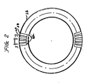
- the gap positioning means includes a plurality of radial grooves 58 formed in rotor sealing face 38 for fluid communication with the pressurized fluid.
- the present invention contemplates as an alternative embodiment forming a plurality of radial grooves in stator sealing face 40.
- the radial grooves are symmetrical about a radial line of rotor sealing face 38 and preferably have a curved cross-sectional configuration. However, grooves having different cross section, such as square cross sections, could be used.
- the plurality of radial grooves are spaced from one another so that a plurality of lands 60 are located therebetween.
- Radial grooves 58 and lands 60 are preferably of uniform width, respectively. Further, in the preferred embodiment the width of radial grooves 58 is approximately equal to the width of lands 60.
- Radial grooves 58 preferably have a width within the range of 0.1 to 0.5 inches and have a depth within the range of 200 to 1000 millionths of an inch.
- radial grooves 58 extend inwardly from the outer periphery of rotor sealing face 38 a distance less than the radial span of rotor sealing face 38.
- the remaining portion of rotor sealing face 38 provides a sealing dam 62 radially downstream to radial grooves 58.
- the radial dam tends to impede the flow of pressurized fluid to the ambient atmosphere and thereby minimize leakage.
- the radial length of radial grooves 58 is larger than the radial length of sealing dam 62.
- sealing dam 62 has a radial length of within the range of at least 40 to 50 thousandths of an inch.
- the seal of the present invention represents a seal capable of producing and maintaining a proper preselected gap or space between rotor and stator sealing faces as a result of the net force generated by the closing and opening forces operating on the seal.
- the seal is specifically configurated to generate self-restoring closing and opening forces capable of producing a predetermined proper gap between the sealing faces.
- the closing force acting on the seal is primarily a function the magnitude of pressure acting on the left side of stator 30, although the force provided by spring 50 also tends to push or slide the stator toward the rotor.
- This spring force is fairly constant, and the magnitude of the spring force becomes insignificant, when the seal is subjected to high pressure.
- the major variables factored into the net hydrostatic pressure acting on the stator include the operating pressure and the area of rear pressure face 52 against which the pressure acts.
- the magnitude of the closing pressure force can be varied by altering the inside diameter of the secondary seal 48 together with the diameter of cup skirt 35 thereby either enlarging or decreasing the surface area subjected to hydrostatic forces.
- Spring 50 serves to keep the rotor and stator sealing faces 38 and 40 together when the machine is not running.
- the force produced by spring 50 is very small in comparison to the hydrostatic pressure load. Once the machine is pressurized, the pressure force quickly exceeds the spring force.
- the opening force placed on the seal is a function of a variety of variables, including the width and length of radial grooves 58, the cross-sectional geometry of radial grooves 58, the pressure of the pressurized fluid, the speed of shaft 22, the size of the gap between the sealing faces, and fluid viscosity.
- pressurized fluid will fill the grooves and create an opening force at the interface of the grooves and the opposing sealing face.
- the radial grooves are sized so that, as the pressure increases to operating pressure, the opening or lifting force at the interface of the grooves and the sealing face will open the sealing faces and create a gap.
- pressurized fluid will create a gap dependent hydrostatic opening force over the entire area of the sealing interface.
- the gap-dependent hydrostatic forces tend to cause the sealing faces to float at operating pressures.
- hydrodynamic opening forces are developed because of fluid shear between the sealing faces in the vicinity of the radial grooves, as shown in Figs. 8 and 9.
- the magnitude of this hydrodynamic force is a function of, inter alia , the radial groove structure of the present invention, the properties of the pressurized fluid, and the size of the space between the rotor and stator.
- the closing and opening forces are interrelated since the magnitude of the hydrostatic and hydrodynamic forces varies relative to the size of the gap.
- the seal of the present invention creates the proper gap size by essentially equalizing the counteracting forces operating thereon.
- the seal is designed so that the gap size is typically approximately 100 millionths of an inch.
- the hydrodynamic force is highly sensitive or reactive to the particular gap size. Generally, a small gap size results in high hydrodynamic and hydrostatic opening forces while a large gap size results in lower opening forces. Extremely high hydrodynamic forces are developed when the rotor and stator almost touch.
- the seal of the present invention thus ensures a non-contact seal at operating pressure and speed.
- the seal of the present invention is designed so that as pressure becomes significant relative to the load applied by spring 50, a self-restoring hydrostatic balance is achieved whereby stator 30 effectively floats on a fluid film.
- the force pressing the stator towards the rotor is the sum of the spring force and the integral of the pressure acting over the rear pressure face 52 of the stator.
- the force tending to press the stator away from the rotor is the integral of the pressure acting on the contacting sealing faces, at the radial grooves 58. This condition is shown generally in Fig. 5.
- the seal is designed so that at operating pressure, the opening force at the interface of the sealing faces slightly overcomes the closing force, thereby creating a slight gap between the sealing faces.
- the pressure distribution profile changes when the gap opens.
- the hydrostatic opening force decreases if the gap between the sealing faces becomes too large.
- the hydrostatic opening and closing forces balance and as shown in Figs. 7 and 7A, the sealing faces float on a fluid film.
- the hydrostatic opening force can be determined by integrating the pressure distribution over the area.
- the pressure at any point is a function of among other things, the gap size, the pressure of the fluid, and the geometry of the radial grooves.
- Figs. 5 and 5A illustrate the hydrostatic effects on rotor and stator sealing faces 38 and 40, at the state where rotor 26 and stator 30 are for practical purposes in contact.
- the pressure on the sealing faces at the radial groove location is a constant P h , representing the maximum pressure of the fluid.
- P h representing the maximum pressure of the fluid.
- the pressure across the sealing dam beyond the radial groove area and between the sealing faces gradually decreases from P h to P l , the ambient pressure.
- Figs. 6 and 6A illustrate the hydrostatic effects on rotor and stator sealing faces 38 and 40 having a large gap, large being relative to radial groove depth, between the respective sealing faces.
- the gap size becomes large, in contrast to Fig. 5A, the fluid flow becomes insensitive to the presence of the radial grooves resulting in relatively continuous pressure drop over a large area.
- the pressure profile of Fig. 6A shows a pressure decrease more smooth or continuous from P h at the outer perimeter of the respective sealing faces to P l at the interior perimeter of rotor 26 and stator 30.
- Figs. 7 and 7A illustrate the hydrostatic effects on rotor and stator sealing faces 38 and 40 when the predetermined proper gap of the present invention is formed between the respective sealing faces. As shown, the pressure along the grooves decreases slightly from P h to P m , and the pressure below the groove changes more rapidly from P m to P l .
- hydrostatic closing force acts on the rear pressure face 52 of stator 30.
- this closing force is determined by specifying the appropriate diameter for cup skirt 35. This diameter defines the location and size of secondary seal 48 and, hence, the surface area subject to a constant hydrostatic closing force.
- the hydrostatic pressure force is much larger than the spring force.
- Figs. 8 and 8A show the hydrodynamic forces at the radial groove area of the present invention.
- stator sealing face 40 is stationary, while the rotor sealing face 28 rotates or slides relative to stator 30.
- the fluid located between the sealing faces is dragged in the direction of moving rotor 26.
- gaseous fluid goes from the edge to the deeper radially rounded area of the radial groove, the gas film experiences an expansion.
- the pressure of the gas drops.
- the pressure drop is limited by the laws of physics, namely, a pressure drop below absolute zero (negative one atmosphere) is impossible.
- the pressure rise is dependent upon the speed, the film thickness and the viscosity of the fluid and, in contrast to the pressure drop, is not limited in magnitude.
- the net opening pressure is larger in magnitude than the ambient or reference pressure because the pressure rise is larger than the pressure drop. This explains why, as shown in Fig. 9, the net opening force created by the grooves increases as the speed of the rotor increases. It has further been found that the net opening force increases as the gap between the faces decreases. This hydrodynamic opening force combines with the hydrostatic opening force when relative sliding motion takes place between the sealing surfaces. This effect further ensures that no face contact will occur between the stator and the rotor.
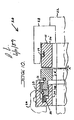
- Fig. 10 shows a second preferred embodiment of the present invention wherein the seal is split and is capable of high temperature service.
- the seal of the second embodiment is primarily based upon the previously described principles and elements except for the replacement of elastomers with high temperature resistant materials.
- the seal of the second embodiment includes segmented stator 30′ and rotor 26′ which are split for easy around-the-shaft replacement. Once stators 30′ and rotor 26′ are properly positioned, they are held in place by securing means.
- the securing means is a split radial spring 29 and a garter spring 31 for holding the split ceramic rotor and the split carbon stator in position, respectively.
- garter spring 31 does not have to apply high loads to hold the two split stator parts together.
- rotor 26′ is subject to high centrifugal forces which tend to separate the split rotor joints.
- radial spring 29 is heavily squeezed between rotor carrier 28 and rotor 26′. This applies high radial closing force on the split rotor and prevents its opening.
- radial spring 29 is split, it cannot serve as a seal in the same way static seal 44 is used in the first embodiment (Fig. 1). Rather, sealing between rotor carrier 28 takes place at the flat interface 45 where simple contact prevents the leakage.
- garter spring 33 can hold the non-elastomer segmented seal 48′ in position.
- the design principles and operation of this second embodiment are the same as those of the previously described seal except the rotor and stator are split for easy around-the shaft replacement.
Landscapes
- Engineering & Computer Science (AREA)
- General Engineering & Computer Science (AREA)
- Mechanical Engineering (AREA)
- Mechanical Sealing (AREA)
- Sealing Devices (AREA)
Applications Claiming Priority (2)
| Application Number | Priority Date | Filing Date | Title |
|---|---|---|---|
| US337828 | 1989-04-14 | ||
| US07/337,828 US5143384A (en) | 1989-04-14 | 1989-04-14 | Bi-directional, non-contact face seal |
Publications (2)
| Publication Number | Publication Date |
|---|---|
| EP0396441A1 true EP0396441A1 (de) | 1990-11-07 |
| EP0396441B1 EP0396441B1 (de) | 1995-01-25 |
Family
ID=23322196
Family Applications (1)
| Application Number | Title | Priority Date | Filing Date |
|---|---|---|---|
| EP90400986A Revoked EP0396441B1 (de) | 1989-04-14 | 1990-04-10 | Drehrichtungsunabhängige kontaktlose Gleitringdichtung |
Country Status (3)
| Country | Link |
|---|---|
| US (1) | US5143384A (de) |
| EP (1) | EP0396441B1 (de) |
| DE (1) | DE69016253T2 (de) |
Cited By (7)
| Publication number | Priority date | Publication date | Assignee | Title |
|---|---|---|---|---|
| FR2646223A1 (fr) * | 1989-04-24 | 1990-10-26 | Sealol Inc Eg G | Joint a anneaux glissants |
| US6257589B1 (en) * | 1996-06-20 | 2001-07-10 | Rexnord Corporation | Aerospace housing and shaft assembly |
| RU2176044C2 (ru) * | 1998-04-02 | 2001-11-20 | Самарский государственный технический университет | Способ регулирования зазора в торцевых уплотнениях и устройство для его реализации |
| RU2386873C1 (ru) * | 2008-09-12 | 2010-04-20 | Закрытое акционерное общество "Научно-исследовательский и конструкторский институт центробежных и роторных компрессоров им. В.Б. Шнеппа" | Уплотнение с активным электромагнитным регулированием зазора |
| RU2404389C2 (ru) * | 2008-12-30 | 2010-11-20 | Закрытое акционерное общество "Научно-исследовательский и конструкторский институт центробежных и роторных компрессоров им. В.Б. Шнеппа" | Тандемное уплотнение с активным электромагнитным регулированием зазоров |
| RU2503865C1 (ru) * | 2012-11-13 | 2014-01-10 | Закрытое акционерное общество "Научно-исследовательский и конструкторский институт центробежных и роторных компрессоров им. В.Б. Шнеппа" | Уплотнение с активным электромагнитным регулированием зазора |
| EP2401491A4 (de) * | 2009-02-27 | 2017-09-06 | Stein Seal Company | Verbessertes luftfilmsiegel |
Families Citing this family (55)
| Publication number | Priority date | Publication date | Assignee | Title |
|---|---|---|---|---|
| US5492341A (en) * | 1990-07-17 | 1996-02-20 | John Crane Inc. | Non-contacting, gap-type seal having a ring with a patterned seal face |
| US5722665A (en) * | 1992-02-26 | 1998-03-03 | Durametallic Corporation | Spiral groove face seal |
| US5441283A (en) * | 1993-08-03 | 1995-08-15 | John Crane Inc. | Non-contacting mechanical face seal |
| AU685502B2 (en) * | 1993-09-01 | 1998-01-22 | Durametallic Corporation | Face seal with angled and annular grooves |
| US5490679A (en) * | 1993-12-20 | 1996-02-13 | John Crane Inc. | Seal ring design |
| US5769604A (en) * | 1995-05-04 | 1998-06-23 | Eg&G Sealol, Inc. | Face seal device having high angular compliance |
| US5997004A (en) * | 1996-10-22 | 1999-12-07 | Flowserve Management Company | Hybrid floating brush seal |
| US5938206A (en) * | 1996-11-01 | 1999-08-17 | John Crane Inc. | Pressure responsive primary ring for a non-contacting mechanical end face seal |
| US6116609A (en) * | 1997-12-17 | 2000-09-12 | A. W. Chesterton Company | Fluidic feedback pressure regulation system for a mechanical seal |
| US6068263A (en) * | 1997-12-17 | 2000-05-30 | A.W. Chesterton Company | Split mechanical face seal with resilient pivoting member |
| US6131912A (en) * | 1997-12-17 | 2000-10-17 | A.W. Chesterton Company | Split mechanical face seal |
| US6068264A (en) * | 1997-12-17 | 2000-05-30 | A.W. Chesterton Company | Split mechanical face seal with negative pressure control system |
| US6059293A (en) * | 1997-12-17 | 2000-05-09 | A.W. Chesterton Company | Split mechanical face seal with seal face fluid introducing structure |
| US6076830A (en) * | 1997-12-17 | 2000-06-20 | A.W. Chesterton Company | Dual non-contacting mechanical face seal having concentric seal faces |
| AU1925999A (en) | 1997-12-17 | 1999-07-05 | A.W. Chesterton Company | Non-contacting mechanical face seal having concentric seal faces |
| US6142479A (en) * | 1998-10-14 | 2000-11-07 | Jm Clipper Corporation | Split labyrinth seal |
| US6299173B1 (en) | 1998-10-16 | 2001-10-09 | John Crane Inc. | Mechanical end face seal ring having a compliant seal face |
| US6416057B1 (en) | 1999-04-16 | 2002-07-09 | Flowserve Management Company | Brush seal |
| US6244599B1 (en) | 1999-04-28 | 2001-06-12 | Flowserve Management Company | Floating brush seal |
| US6655695B1 (en) * | 2001-02-13 | 2003-12-02 | Honeywell International Inc. | Face seal assembly with composite rotor |
| GB2375148A (en) * | 2001-04-30 | 2002-11-06 | Corac Group Plc | A dry gas seal |
| US6932567B2 (en) * | 2002-12-19 | 2005-08-23 | General Electric Company | Method and apparatus for controlling fluid leakage through gas turbine engines |
| US6969236B2 (en) * | 2003-08-29 | 2005-11-29 | Honeywell International, Inc. | Fluid-cooled mechanical face seal rotor |
| US7905493B2 (en) * | 2004-08-26 | 2011-03-15 | GM Global Technology Operations LLC | Sealing system assembly for high pressure fluid handling devices |
| US20060207834A1 (en) * | 2005-03-03 | 2006-09-21 | Honeywell International, Inc. | Aircraft engine accessory drive air film riding bulkhead seal |
| US20080003099A1 (en) * | 2006-06-30 | 2008-01-03 | Honeywell International, Inc. | Closed bias air film riding seal in event of housing breach for shared engine lubrication accessory gearboxes |
| US8162322B2 (en) * | 2006-10-25 | 2012-04-24 | Rexnord Industries, Llc | Hydrodynamic seal with circumferentially varying lift force |
| US9790863B2 (en) | 2013-04-05 | 2017-10-17 | Honeywell International Inc. | Fluid transfer seal assemblies, fluid transfer systems, and methods for transferring process fluid between stationary and rotating components using the same |
| US9534502B2 (en) | 2014-03-26 | 2017-01-03 | General Electric Company | Individually compliant segments for split ring hydrodynamic face seal |
| US9611749B2 (en) | 2014-03-26 | 2017-04-04 | General Electric Company | Face seal with locally compliant hydrodynamic pads |
| US10234036B2 (en) | 2015-01-12 | 2019-03-19 | Rolls-Royce Corporation | Wide differential pressure range air riding carbon seal |
| US9759079B2 (en) | 2015-05-28 | 2017-09-12 | Rolls-Royce Corporation | Split line flow path seals |
| US10458263B2 (en) | 2015-10-12 | 2019-10-29 | Rolls-Royce North American Technologies Inc. | Turbine shroud with sealing features |
| US10415707B2 (en) | 2016-06-30 | 2019-09-17 | General Electric Company | Face seal assembly and an associated method thereof |
| US10626743B2 (en) | 2016-06-30 | 2020-04-21 | General Electric Company | Segmented face seal assembly and an associated method thereof |
| US10697314B2 (en) | 2016-10-14 | 2020-06-30 | Rolls-Royce Corporation | Turbine shroud with I-beam construction |
| US10788398B2 (en) | 2016-12-23 | 2020-09-29 | Rolls-Royce Corporation | Gas turbine engine test stand |
| US10718226B2 (en) | 2017-11-21 | 2020-07-21 | Rolls-Royce Corporation | Ceramic matrix composite component assembly and seal |
| US10774876B1 (en) * | 2019-04-25 | 2020-09-15 | Freudenberg-Nok General Partnership | Hydrodynamic thrust washers with pumping features for sparse lubrication applications |
| US11454324B2 (en) * | 2020-08-26 | 2022-09-27 | Raytheon Technologies Corporation | Face seal carrier arrester |
| US11821320B2 (en) | 2021-06-04 | 2023-11-21 | General Electric Company | Turbine engine with a rotor seal assembly |
| US12270304B2 (en) | 2021-07-26 | 2025-04-08 | General Electric Company | Turbine engine with a floating seal assembly |
| US12000289B2 (en) | 2022-03-10 | 2024-06-04 | General Electric Company | Seal assemblies for turbine engines and related methods |
| US12006829B1 (en) | 2023-02-16 | 2024-06-11 | General Electric Company | Seal member support system for a gas turbine engine |
| US12486779B2 (en) | 2023-03-08 | 2025-12-02 | General Electric Company | Seal support assembly for a turbine engine |
| US12116896B1 (en) | 2023-03-24 | 2024-10-15 | General Electric Company | Seal support assembly for a turbine engine |
| US12241375B2 (en) | 2023-03-24 | 2025-03-04 | General Electric Company | Seal support assembly for a turbine engine |
| US12421861B2 (en) | 2023-03-24 | 2025-09-23 | General Electric Company | Seal support assembly for a turbine engine |
| US12215587B2 (en) | 2023-03-24 | 2025-02-04 | General Electric Company | Seal support assembly for a turbine engine |
| US12595745B2 (en) | 2023-03-24 | 2026-04-07 | General Electric Company | Seal support assembly for a turbine engine |
| US12372002B2 (en) | 2023-03-24 | 2025-07-29 | General Electric Company | Seal support assembly for a turbine engine |
| US12416243B2 (en) | 2023-03-24 | 2025-09-16 | General Electric Company | Seal support assembly for a turbine engine |
| US12215588B2 (en) | 2023-03-27 | 2025-02-04 | General Electric Company | Seal assembly for a gas turbine engine |
| US12326089B2 (en) | 2023-04-24 | 2025-06-10 | General Electric Company | Seal assembly for a gas turbine engine |
| US12584415B2 (en) | 2024-05-03 | 2026-03-24 | General Electric Company | Turbine engine seal for turbine engines |
Citations (2)
| Publication number | Priority date | Publication date | Assignee | Title |
|---|---|---|---|---|
| DE1964150A1 (de) * | 1968-12-30 | 1970-07-16 | Westinghouse Electric Corp | Dichtungsanordnung zur Begrenzung von Stroemungsmittelstroemungen laengs drehbarer Wellen |
| EP0298324A2 (de) * | 1987-07-06 | 1989-01-11 | Feodor Burgmann Dichtungswerke GmbH & Co. | Gleitringdichtung zur Abdichtung eines gasförmigen Mediums |
Family Cites Families (22)
| Publication number | Priority date | Publication date | Assignee | Title |
|---|---|---|---|---|
| US2921806A (en) * | 1955-11-08 | 1960-01-19 | William G Carter | Shaft seal |
| US3068801A (en) * | 1958-09-02 | 1962-12-18 | Murray William | Centrifugal impeller pumps |
| GB917693A (en) * | 1960-09-23 | 1963-02-06 | Us Metallic Packing Company Lt | Improvements in or relating to rotary shaft packings |
| GB920892A (en) * | 1961-01-17 | 1963-03-13 | Gen Electric Co Ltd | Improvements in or relating to seals for gas filled machines |
| US3244425A (en) * | 1961-09-23 | 1966-04-05 | Crane Packing Ltd | Axially biased rotary face seal |
| US3495841A (en) * | 1964-05-25 | 1970-02-17 | Sealol | High pressure fluid seal with controlled leakage |
| US3511510A (en) * | 1964-05-25 | 1970-05-12 | Sealol | High pressure fluid seal with biasing action |
| US3410565A (en) * | 1966-07-27 | 1968-11-12 | Worthington Corp | Centrifugal and face contact seal |
| FR1599308A (de) * | 1968-06-08 | 1970-07-15 | ||
| US3751045A (en) * | 1970-03-19 | 1973-08-07 | Ingersoll Rand Co | Fluid seal |
| US3640541A (en) * | 1970-06-12 | 1972-02-08 | Koppers Co Inc | Hydrodynamic lift-type face seal |
| US3675935A (en) * | 1970-07-13 | 1972-07-11 | Nasa | Spiral groove seal |
| US4407512A (en) * | 1976-01-02 | 1983-10-04 | John Crane-Houdaille, Inc. | High pressure rotary mechanical seal |
| US4082296A (en) * | 1976-05-26 | 1978-04-04 | Stein Philip C | Seal for sealing between a rotating member and a housing |
| US4212475A (en) * | 1979-01-15 | 1980-07-15 | Crane Packing Co. | Self aligning spiral groove face seal |
| JPS5613513U (de) * | 1979-07-10 | 1981-02-05 | ||
| AU536164B2 (en) * | 1979-11-21 | 1984-04-19 | Ifield Engineering Pty. Ltd. | Hydraulic pump or motor |
| IL65289A0 (en) * | 1982-03-19 | 1982-05-31 | Lipschitz Abraham | Hydrodynamic non-contacting seal for rotary machines |
| DE3223703C2 (de) * | 1982-06-25 | 1984-05-30 | M.A.N. Maschinenfabrik Augsburg-Nürnberg AG, 4200 Oberhausen | Gasgesperrte Wellendichtung mit radialem Dichtspalt |
| JPS599367A (ja) * | 1982-07-07 | 1984-01-18 | Hitachi Ltd | 軸封装置 |
| US4511149A (en) * | 1983-09-29 | 1985-04-16 | Borg-Warner Corporation | Mechanical seal with cylindrical balance sleeve |
| GB2179409A (en) * | 1985-08-20 | 1987-03-04 | Angus George Co Ltd | Face seal with pumping action |
-
1989
- 1989-04-14 US US07/337,828 patent/US5143384A/en not_active Expired - Fee Related
-
1990
- 1990-04-10 EP EP90400986A patent/EP0396441B1/de not_active Revoked
- 1990-04-10 DE DE69016253T patent/DE69016253T2/de not_active Revoked
Patent Citations (2)
| Publication number | Priority date | Publication date | Assignee | Title |
|---|---|---|---|---|
| DE1964150A1 (de) * | 1968-12-30 | 1970-07-16 | Westinghouse Electric Corp | Dichtungsanordnung zur Begrenzung von Stroemungsmittelstroemungen laengs drehbarer Wellen |
| EP0298324A2 (de) * | 1987-07-06 | 1989-01-11 | Feodor Burgmann Dichtungswerke GmbH & Co. | Gleitringdichtung zur Abdichtung eines gasförmigen Mediums |
Non-Patent Citations (1)
| Title |
|---|
| WORLD PUMPS, no. 10, October 1985, pages 297-300, Morden, Surrey, GB; "Dry running gas seals" * |
Cited By (7)
| Publication number | Priority date | Publication date | Assignee | Title |
|---|---|---|---|---|
| FR2646223A1 (fr) * | 1989-04-24 | 1990-10-26 | Sealol Inc Eg G | Joint a anneaux glissants |
| US6257589B1 (en) * | 1996-06-20 | 2001-07-10 | Rexnord Corporation | Aerospace housing and shaft assembly |
| RU2176044C2 (ru) * | 1998-04-02 | 2001-11-20 | Самарский государственный технический университет | Способ регулирования зазора в торцевых уплотнениях и устройство для его реализации |
| RU2386873C1 (ru) * | 2008-09-12 | 2010-04-20 | Закрытое акционерное общество "Научно-исследовательский и конструкторский институт центробежных и роторных компрессоров им. В.Б. Шнеппа" | Уплотнение с активным электромагнитным регулированием зазора |
| RU2404389C2 (ru) * | 2008-12-30 | 2010-11-20 | Закрытое акционерное общество "Научно-исследовательский и конструкторский институт центробежных и роторных компрессоров им. В.Б. Шнеппа" | Тандемное уплотнение с активным электромагнитным регулированием зазоров |
| EP2401491A4 (de) * | 2009-02-27 | 2017-09-06 | Stein Seal Company | Verbessertes luftfilmsiegel |
| RU2503865C1 (ru) * | 2012-11-13 | 2014-01-10 | Закрытое акционерное общество "Научно-исследовательский и конструкторский институт центробежных и роторных компрессоров им. В.Б. Шнеппа" | Уплотнение с активным электромагнитным регулированием зазора |
Also Published As
| Publication number | Publication date |
|---|---|
| DE69016253T2 (de) | 1995-05-24 |
| EP0396441B1 (de) | 1995-01-25 |
| DE69016253D1 (de) | 1995-03-09 |
| US5143384A (en) | 1992-09-01 |
Similar Documents
| Publication | Publication Date | Title |
|---|---|---|
| US5143384A (en) | Bi-directional, non-contact face seal | |
| US5133562A (en) | Drained face seal | |
| EP0578377B1 (de) | Abdichtung | |
| KR0164616B1 (ko) | 밀봉장치 | |
| US3499653A (en) | Rotary mechanical seal of the gap type | |
| EP1600673B1 (de) | Gleitringdichtung mit Rückfördervorrichtung | |
| EP0595437B1 (de) | Gleitringdichtung | |
| EP0623768B1 (de) | Labyrinth-Gasdichtung | |
| US5516118A (en) | Circumferential hydrodynamic seals for sealing a bidirectionally rotatable member | |
| US5169159A (en) | Effective sealing device for engine flowpath | |
| US5435574A (en) | Contactless pressurizing-gas shaft seal | |
| US6494462B2 (en) | Rotary seal with improved dynamic interface | |
| EP0564153B1 (de) | Gleitringdichtung mit doppelten Spiralrillen | |
| US4972986A (en) | Circumferential inter-seal for sealing between relatively rotatable concentric shafts | |
| US5370403A (en) | Non-contacting face seal | |
| US3586342A (en) | Hydrodynamic shaft seal | |
| US5217232A (en) | Thermally regulated segmented seal | |
| US4722534A (en) | Face seal with automatic face convergence means | |
| JPH09503276A (ja) | 角度をつけた円環状の溝を有する面封止装置 | |
| US5531458A (en) | Face seal with angled grooves | |
| EP0187059B1 (de) | Axiale Dichtung mit verstellbarer Friktion für Gleitringdichtungen | |
| EP0670976B1 (de) | Hydrodynamisch geschmierte wellendichtung mit torsionsfester geometrie | |
| US5192083A (en) | Single ring sector seal | |
| US5026076A (en) | Mechanical face seals | |
| Lipschitz | A zero-leakage film riding face seal |
Legal Events
| Date | Code | Title | Description |
|---|---|---|---|
| PUAI | Public reference made under article 153(3) epc to a published international application that has entered the european phase |
Free format text: ORIGINAL CODE: 0009012 |
|
| AK | Designated contracting states |
Kind code of ref document: A1 Designated state(s): DE FR GB IT |
|
| 17P | Request for examination filed |
Effective date: 19910507 |
|
| 17Q | First examination report despatched |
Effective date: 19921120 |
|
| GRAA | (expected) grant |
Free format text: ORIGINAL CODE: 0009210 |
|
| AK | Designated contracting states |
Kind code of ref document: B1 Designated state(s): DE FR GB IT |
|
| REF | Corresponds to: |
Ref document number: 69016253 Country of ref document: DE Date of ref document: 19950309 |
|
| ET | Fr: translation filed | ||
| ITF | It: translation for a ep patent filed | ||
| PLBI | Opposition filed |
Free format text: ORIGINAL CODE: 0009260 |
|
| 26 | Opposition filed |
Opponent name: PACIFIC WIETZ GMBH & CO. KG Effective date: 19951007 |
|
| PLBF | Reply of patent proprietor to notice(s) of opposition |
Free format text: ORIGINAL CODE: EPIDOS OBSO |
|
| PLBF | Reply of patent proprietor to notice(s) of opposition |
Free format text: ORIGINAL CODE: EPIDOS OBSO |
|
| PGFP | Annual fee paid to national office [announced via postgrant information from national office to epo] |
Ref country code: FR Payment date: 19970318 Year of fee payment: 8 |
|
| PGFP | Annual fee paid to national office [announced via postgrant information from national office to epo] |
Ref country code: DE Payment date: 19970324 Year of fee payment: 8 |
|
| PGFP | Annual fee paid to national office [announced via postgrant information from national office to epo] |
Ref country code: GB Payment date: 19970326 Year of fee payment: 8 |
|
| PG25 | Lapsed in a contracting state [announced via postgrant information from national office to epo] |
Ref country code: GB Free format text: LAPSE BECAUSE OF NON-PAYMENT OF DUE FEES Effective date: 19980410 |
|
| RDAH | Patent revoked |
Free format text: ORIGINAL CODE: EPIDOS REVO |
|
| RDAG | Patent revoked |
Free format text: ORIGINAL CODE: 0009271 |
|
| STAA | Information on the status of an ep patent application or granted ep patent |
Free format text: STATUS: PATENT REVOKED |
|
| GBPC | Gb: european patent ceased through non-payment of renewal fee |
Effective date: 19980410 |
|
| 27W | Patent revoked |
Effective date: 19980724 |