EP0396517A1 - Verfahren zur Faltung von numerischen Bildern - Google Patents
Verfahren zur Faltung von numerischen Bildern Download PDFInfo
- Publication number
- EP0396517A1 EP0396517A1 EP90850123A EP90850123A EP0396517A1 EP 0396517 A1 EP0396517 A1 EP 0396517A1 EP 90850123 A EP90850123 A EP 90850123A EP 90850123 A EP90850123 A EP 90850123A EP 0396517 A1 EP0396517 A1 EP 0396517A1
- Authority
- EP
- European Patent Office
- Prior art keywords
- image
- processing
- processing means
- picture element
- element values
- Prior art date
- Legal status (The legal status is an assumption and is not a legal conclusion. Google has not performed a legal analysis and makes no representation as to the accuracy of the status listed.)
- Granted
Links
Images




Classifications
-
- G—PHYSICS
- G06—COMPUTING OR CALCULATING; COUNTING
- G06T—IMAGE DATA PROCESSING OR GENERATION, IN GENERAL
- G06T3/00—Geometric image transformations in the plane of the image
- G06T3/40—Scaling of whole images or parts thereof, e.g. expanding or contracting
- G06T3/4007—Scaling of whole images or parts thereof, e.g. expanding or contracting based on interpolation, e.g. bilinear interpolation
-
- G—PHYSICS
- G06—COMPUTING OR CALCULATING; COUNTING
- G06F—ELECTRIC DIGITAL DATA PROCESSING
- G06F17/00—Digital computing or data processing equipment or methods, specially adapted for specific functions
- G06F17/10—Complex mathematical operations
- G06F17/17—Function evaluation by approximation methods, e.g. inter- or extrapolation, smoothing, least mean square method
- G06F17/175—Function evaluation by approximation methods, e.g. inter- or extrapolation, smoothing, least mean square method of multidimensional data
-
- H—ELECTRICITY
- H04—ELECTRIC COMMUNICATION TECHNIQUE
- H04N—PICTORIAL COMMUNICATION, e.g. TELEVISION
- H04N19/00—Methods or arrangements for coding, decoding, compressing or decompressing digital video signals
- H04N19/50—Methods or arrangements for coding, decoding, compressing or decompressing digital video signals using predictive coding
- H04N19/503—Methods or arrangements for coding, decoding, compressing or decompressing digital video signals using predictive coding involving temporal prediction
- H04N19/51—Motion estimation or motion compensation
- H04N19/537—Motion estimation other than block-based
Definitions
- the present invention relates to a graphics processing system and more particularly to a system for processing and displaying images.
- the present invention more specifically relates to apparatus and methods for processing an image defined as a set of picture elements in order to enhance the image, perform pattern detection, or analyze the scene.
- the system also provides for a method of enlarging selected portions of the image through a zoom process.
- Image analysis and enhancement can be accomplished through the use of filters applied to the image data.
- Image data collected from an image input-device is stored as a series of picture elements (or pixels).
- a procedure may be employed to analyze these pixels to create a new image that enhances certain image features.
- a procedure may be applied which results in an image showing an outline of objects contained in the original image.
- the application of this analysis procedure is called filtering and the procedure itself is a filter.
- the present invention implements a means and process for filtering.
- a second problem addressed by the present invention is that of enlarging an image while maintaining the quality of that image on the display.
- the original scanned image is comprised of a fixed number of picture elements that make up that image. Enlargement of a certain portion of that image can result in an extremely grainy image if the existing picture elements are simply enlarged.
- the technique of bi-linear interpolation provides a means for enlarging an image in such a manner that the resulting image retains the quality of the original image.
- bi-linear interpolation uses the information available at adjacent pixels to interpolate the appropriate color, and intensity values for the enlarged image.
- the resulting image will retain the characteristics of the original image.
- the present invention is implemented as part of a raster graphics display system.
- a typical raster graphics display system is shown in Fig. 1.
- the system communicates with a host processor through host communications interface 102.
- System functions are controlled by system control processor 104 which is responsible for servicing all attached graphics input/output devices such as a tablet and a keyboard.
- the system control processor coordinates the processing of display processor 108 and the host system interface.
- Graphics and image processing programs and image data are stored in system memory 106 after being downloaded from the host computer through communications interface 102.
- Display processor 108 is responsible for executing the graphics and image commands which reside in the system memory and produces the resulting image that will appear on display monitor 114.
- the display processor when operating in a graphics mode, decodes graphics orders to generate a graphics object for display. In processing the graphics order, display processor 108 performs transformation, clipping, and mapping of geometric primitives such as lines, characters and polygons. Data generated by the display processor 108 is passed to the vector generator 110 which generates the pixels of the resulting image to be placed in video pixel memory 112.
- Video pixel memory 112 stores the image data for display on video monitor 114.
- video pixel memory 112 consists of eight 1Kx1K bit planes supporting 256 colors simultaneously through the use of color lookup tables.
- the video pixel memory 112 can be extended to 24 bit planes with 8 bit planes for each of three colors, e.g. red, green, and blue.
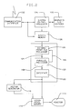
- a graphics and image processing system is shown functionally in Fig. 2.
- the logical data flow of the system is as follows.
- An application program is loaded from the host processor through the host communication interface 102 into system memory 106.
- Keyboard commands and graphics device input generated by the I/O devices 105 are processed by system control processor 104 and, if necessary, stored in system memory 106.
- the system control processor performs any required preprocessing and then interrupts the display processor 108 causing it to process the data.
- Data processed by display processor 108 is either written directly to the video pixel memory 112 or, if vector generation is required, is passed to vector generator 110 which creates the necessary image to be written to video pixel memory 112.
- the final image is generated from video pixel memory 112 onto display monitor 114.
- Parallel processor section 150 is shown in greater detail in Fig. 3.
- processor section 150 consists of seven processing units configured so that three of the processing units operate in parallel and four others sequentially. The entire parallel processor section operates in a pipeline fashion so that data is continually processed through the section without waiting for completion of all processing by any single processor.
- Processors 152, 154, and 156 operate in parallel with the output passed to sequentially linked processors 160, 162, 164 and 166.
- the output of processor 166 is passed to the interface section 122 along line 168.
- the processing by decoder 120 sets up the parallel processing section for processing and communicates to it via line 124. Feedback from the parallel processing section is provided by line 126 which in turn is connected to decoder 120.
- the floating point processors employed in the parallel processor section can be any general purpose floating point processor.
- a processor with 32-bit floating point capability is employed.
- the Transputer by INMOS Technologies can be employed in this application. (Transputer is a trademark of INMOS.)
- the selected floating point processor must have a floating point multiplier, floating point adder, simple sequencer, a first-in first-out queue for input and another for output, and internal registers for storing the kernel function.
- parallel processors 152, 154, and 156 perform image filter convolution.
- Processor 160 synchronizes the data from the parallel processors, and passes it to processor 162 for lower bound clipping and then to processor 164 for upper bound clipping.
- Processor 166 converts the floating point values to fixed point and passes the result to video pixel memory 112.
- image processing filtering and bi-linear interpolation using this parallel processing architecture requires a discussion of the algorithms employed in filtering and bi-linear interpolation.
- the method of the present invention was designed to perform convolution of discrete data for use as digital image filter. Convolutions can be used to perform high pass filtering, low pass filtering, band pass filtering (for noise removal), high boost filtering (providing edge enhancement), edge detection, and directional feature enhancement.
- Fig. 4 illustrates a source image pixel array having c columns numbered 1 through c, and r rows numbered 1 through r.
- the source image pixel array represents an image that is to be filtered.
- the source image can be any scanned image, such as that from satellite based image detectors, x-ray equipment, or other medical imaging devices.
- Each pixel of the image is represented in Fig. 4 by the letter (S rc ), where r indicates the row and c the column.
- the digital image is represented by a color intensity value stored at each location.
- the image can be stored as a monochrome image of varying intensity values or as a color image with intensity values for each represented color.
- the image data is stored in an eight bit per pixel per color format.
- each pixel requires the storage of 24 bits.
- the present method is designed to operate on each color separately and therefore process eight bits per pixel.
- Each pixel has an intensity value of 0 to 255 for each color. Because each color is independent of the other two colors, additional hardware may be added so that all three color components can be computed simultaneously.
- the digital filtering to be employed in a particular case is defined by the kernel function convolved with the original image.
- This kernel is specified in the preferred embodiment as a 3x3 matrix as shown in Fig. 5.
- the present invention employs a 3x3 kernel, however, the method described herein can be extended to kernels of larger or smaller sizes. Larger kernels result in more ideal (i.e. higher order) filtering at the expense of increased processing time.
- the output image pixel array is illustrated in Fig. 6 and comprises an image of the same dimensions (r x c) as the source image pixel array.
- the value of each output image pixel b ij is a function of the source image pixel S ij and the eight pixels surrounding the source pixel.
- the function applied to the source image is specified by the kernel function as shown in Fig. 5. For each 3x3 sub-matrix of the source image convolution with the kernel function results in a single output pixel.
- the calculation of a single output pixel b ij requires nine multiplications and eight additions or a total of seventeen operations.
- the present invention is directed to a method of speeding up the calculation of the filtered image. Processing of the entire source image requires successive applications of the kernel to successive sub-matrices of the source image S.
- Fig. 7 depicts a flow chart describing the method.
- the front end processor 120 begins by adding boundary lines on each side of the image 170. For processing with a 3x3 kernel, one line is added on each side resulting in an image as shown in Fig. 8.
- the additional boundary lines are necessary so that the processor can always deal with a 3x3 sub-matrix even at the extreme edges of the original image. This eliminates the need for additional logic to process the boundary conditions. If a kernel larger than 3x3 is employed, additional boundary lines will need to be added.
- the second step 172 reads three lines of source image data into a processing buffer.
- the initial lines read will be: h00 h01 h02 ... h 0c+1 h10 S11 S12 ... h 1c+1 h20 S21 S22 ... h 2c+1 .
- the next processor step 174 sends one column from the three buffers to the floating point processors. An additional column is sent after each series of three machine cycles, in the preferred embodiment.
- the floating point processors carry out step 176, accumulation of the output image pixel. If computation has been completed 178 the floating point processor sends the computed output pixel b ij 180 and clears the accumulator to begin computation of the next pixel. Otherwise, the processor calculates the inner product of the column sent by step 174 and the transpose of a column of the kernel function.
- a test for an end of a row condition is required 182. If not at the end of the row, control returns to the front end processor 120 which sends another column to the processor 174. If the end of the row has been reached, the next line of the source image is read into the buffers 184. If no lines remain 186, image processing is completed and control passes to the next operation. Otherwise, control returns to the front end processor 120 to continue sending a column at a time from the buffers to the parallel processors. It should be noted that the lines are processed three lines at a time buc, upon reaching the end of a row, only one line is replaced. This is consistent with the single row increment of the sub-matrix necessary to properly calculate each pixel in the output image pixel array.
- the parallel processors each perform the accumulation testing and output steps 176, 178, and 180. After reaching steady state, which requires nine cycles for a 3x3 convolution kernel, the processor array will compute a new pixel every additional three cycles.
- the three floating point processors are arranged so that the input and output functions are synchronized between the processors. That is, each processor reads at the same time and writes at the same time.
- the method of calculating the convolution is set up so that the processors are out of phase by three machine cycles so that valid data will be sent from only one processor at a time to the subsequent processor.
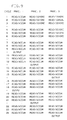
- Fig. 9 illustrates the processing cycles for each of the processors in the first 24 processing cycles.
- Processor 1 first begins the calculation of output image pixel b11. This calculation will be based on the sub-matrix of nine elements as follows: h00 h01 h02 h10 S11 S12 h20 S21 S22 The convolution kernel presented in Fig. 5 will be applied to this sub-matrix.
- Step 174 sends the first column of the source matrix (h00, h10, h20) to all three processors.
- step 1 of Fig. 9 all three processors read the first element h00 from the buffer column.
- Processor 1 accumulates the product of h00 and k11 while processors 2 and 3 ignore the value read.
- processor 1 adds the product of h10 and k21 to the previously accumulated value while processors 2 and 3 ignore the new value.
- processor 1 reads value h20 and accumulates h20*k31 while processors 2 and 3 again ignore the value.
- Front end processor 120 next passes the second column (h01, S11, S21) to the processors.
- processor 2 will begin accumulation of output pixel b12.
- step 4 all three processors read value h01 and processor 1 accumulates the value of h01*k12 while processor 2 accumulates the value of h01*k11.
- Processor 3 ignores the h01 value.
- processor 3 will begin to accumulate the value for output pixel b13.
- step 9 the value for output pixel b11 has been accumulated in processor 1 and is available as output.
- the output of processors 2 and 3 are set to null.
- processors 1 and 3 present null values.
- processor 3 has the value of pixel b13 as output.
- processor 1 is able to send the value for pixel b14. Thereafter, the pattern continues to repeat with each processor putting out a value every nine cycles, with one pixel being created every three cycles by one of the processors.
- the processing time for this convolution method is three times faster than using a single serial process.
- the processors must be re-initialized for nine cycles at the beginning of each new row of the sub-matrix.
- Floating point processor 160 synchronizes the data from the three parallel processors and passes it to processor 162.
- Processor 162 ensures that the floating point data has a positive data value.
- Processor 164 truncates the data to ensure that it is within the fixed point range of the frame buffer.
- processor 166 converts the data from floating point format back into fixed point format and sends it to the video pixel memory.
- Fig. 10(a) through 10(e) represent various kernels to accomplish differ lengthyent objectives.
- Fig. 10(a) is a low pass filter kernel which tends to blur an image.
- Fig. 10(b) is a high pass filter that results in an image in which only the outline of the initial image features remain.
- a high boost filter is shown in Fig. 10()c which provides edge enhancement like the high pass filter but also preserves most of the low frequency components.
- the directional high pass filter kernels shown in Fig. 10(d) are useful for land surveying and other tasks in which it is desirable to accentuate certain features based on their orientation and to suppress features orthogonal to the direction of interest.
- Fig. 10(e) presents additional edge detection kernels.
- the second function to be implemented by the hardware arrangement is bi-linear interpolation used for continuous zoom of a source image.
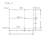
- Fig. 11 is used to illustrate the concept of bi-linear interpolation.
- the outer four pixels P(a,b), P(a+1,b), P(a,b+1) and P(a+1,b+1) represent four adjacent pixels of a source image.
- pixels in the original image will no longer be located on physically addressable points on the display. This requires the computation of new pixel values based on the transformed original pixels.
- Pixel Q(m,n) in Fig. 11 represents a pixel to be interpolated based on the four pixels in the source image. Bi-linear interpolation operates on four adjacent pixels to produce a pixel interior to those four pixels.
- the value of Q(m,n) can be calculated by interpolating between values Q(m) and Q(n). These may in turn be determined by two separate interpolations, Q(m) as an interpolation between P(a,b) and P(a+1,b) and Q(n) as an interpolation between P(a,b+1) and P(a+1,b+1).
- the method for transforming the source image using bi-linear interpolation uses two of the floating point processors in parallel 152 and 154 to generate bi-linear interpolation.
- Front end processor 120 selects and reads two lines of the source image for processing at a time.
- the two parallel processors 152 and 154 perform the horizontal interpolation for Q(m) and Q(n) and monitor the pixel boundary.
- Processor 160 accepts the output of processors 152 and 154 and performs the vertical interpolation to generate Q(m,n). This processor generates pixel values for a series of pixels in a column.
- Processor 162 insures that the calculated intensity value is greater than or equal to zero while processor 164 insures that it is less than or equal to the maximum number allowed, in the preferred embodiment, 255. Finally, processor 166 converts the data from floating point format to fixed point format and sends it to the video pixel memory.
- the zoom factor, T indicates the number of pixels to be generated within each set of four neighboring pixels of the source image. For example if the zoom factor is 15.3 then there will be 16x16 pixels insides the first four pixels of the source image. Thus, starting at pixel (a,b) processor 152 will interpolate an additional 15 points on the horizontal line between P(a,b) and P(a+1,b). Similarly processor 154 will begin at point P(a,b+1) and will interpolate an additional 15 points on the horizontal line between at point P(a+1,b+1). Finally, processor 160 will interpolate between each of the points generated by processors 152 and 154 with the result that a 16x16 output matrix is created.
Landscapes
- Engineering & Computer Science (AREA)
- Physics & Mathematics (AREA)
- General Physics & Mathematics (AREA)
- Theoretical Computer Science (AREA)
- Pure & Applied Mathematics (AREA)
- Computational Mathematics (AREA)
- Mathematical Analysis (AREA)
- Mathematical Optimization (AREA)
- Data Mining & Analysis (AREA)
- Mathematical Physics (AREA)
- Signal Processing (AREA)
- Algebra (AREA)
- Databases & Information Systems (AREA)
- Software Systems (AREA)
- General Engineering & Computer Science (AREA)
- Multimedia (AREA)
- Image Processing (AREA)
Applications Claiming Priority (2)
| Application Number | Priority Date | Filing Date | Title |
|---|---|---|---|
| US34472189A | 1989-04-28 | 1989-04-28 | |
| US344721 | 1989-04-28 |
Publications (2)
| Publication Number | Publication Date |
|---|---|
| EP0396517A1 true EP0396517A1 (de) | 1990-11-07 |
| EP0396517B1 EP0396517B1 (de) | 1996-01-17 |
Family
ID=23351728
Family Applications (1)
| Application Number | Title | Priority Date | Filing Date |
|---|---|---|---|
| EP19900850123 Expired - Lifetime EP0396517B1 (de) | 1989-04-28 | 1990-04-02 | Verfahren zur Faltung von numerischen Bildern |
Country Status (4)
| Country | Link |
|---|---|
| EP (1) | EP0396517B1 (de) |
| JP (1) | JP2565580B2 (de) |
| CA (1) | CA2011507A1 (de) |
| DE (1) | DE69024842T2 (de) |
Cited By (6)
| Publication number | Priority date | Publication date | Assignee | Title |
|---|---|---|---|---|
| EP0504272A4 (en) * | 1989-12-05 | 1993-11-18 | E.I. Du Pont De Nemours And Company | A parallel processing network that corrects for light scattering in image scanners |
| EP0576696A1 (de) * | 1992-06-29 | 1994-01-05 | International Business Machines Corporation | Einrichtung und Verfahren zur schnellen Transformation und zum Anzeigen von zwei- oder dreidimensionalen Bildern mit Anwendung einer Pipelinevorrichtung |
| EP0511606A3 (de) * | 1991-04-29 | 1994-08-03 | Du Pont | |
| GB2313992A (en) * | 1996-03-27 | 1997-12-10 | Mitsubishi Electric Corp | Geometrical operation apparatus |
| EP0908845A1 (de) * | 1997-10-09 | 1999-04-14 | Agfa-Gevaert N.V. | Verfahren zur Verbesserung der Schärfe und zur Wiederabtastung eines Bildes |
| US6222173B1 (en) | 1997-10-09 | 2001-04-24 | Agfa-Gevaert | Image sharpening and re-sampling method |
Citations (1)
| Publication number | Priority date | Publication date | Assignee | Title |
|---|---|---|---|---|
| EP0269993A2 (de) * | 1986-12-01 | 1988-06-08 | Sakata Inx Corporation | Bildverarbeitungsverfahren und -system zur Bildrekonstruktion |
Family Cites Families (2)
| Publication number | Priority date | Publication date | Assignee | Title |
|---|---|---|---|---|
| JP2502495B2 (ja) * | 1984-08-27 | 1996-05-29 | 松下電器産業株式会社 | 画像処理装置 |
| JPS6170655A (ja) * | 1984-09-13 | 1986-04-11 | Fujitsu Ltd | アレイ・プロセツサ装置制御方式 |
-
1990
- 1990-03-05 CA CA 2011507 patent/CA2011507A1/en not_active Abandoned
- 1990-04-02 EP EP19900850123 patent/EP0396517B1/de not_active Expired - Lifetime
- 1990-04-02 DE DE1990624842 patent/DE69024842T2/de not_active Expired - Fee Related
- 1990-04-27 JP JP2110658A patent/JP2565580B2/ja not_active Expired - Lifetime
Patent Citations (1)
| Publication number | Priority date | Publication date | Assignee | Title |
|---|---|---|---|---|
| EP0269993A2 (de) * | 1986-12-01 | 1988-06-08 | Sakata Inx Corporation | Bildverarbeitungsverfahren und -system zur Bildrekonstruktion |
Non-Patent Citations (3)
| Title |
|---|
| COMPUTER TECHNOLOGY REVIEW, vol. 4, no. 4, 1984, pages 153,156,158-159, Los Angeles, California, US; A. BRIDGES: "Multiple processors, optical disk recorders boost graphics systems" * |
| ELEVENTH COLLOQUIUM GRETSI, Nice, 1st - 5th June 1987, pages 649-652; P. DUCLOS et al.: "Mise en oeuvre d'algorithmes de transformations geometriques sur une architecture parallele de type SIMD/SPMD" * |
| PATENT ABSTRACTS OF JAPAN, vol. 6, no. 34 (P-104)[912], 2nd March 1982; & JP-A-56 152 070 (MITSUBISHI DENKI K.K.) 25-11-1981 * |
Cited By (9)
| Publication number | Priority date | Publication date | Assignee | Title |
|---|---|---|---|---|
| EP0504272A4 (en) * | 1989-12-05 | 1993-11-18 | E.I. Du Pont De Nemours And Company | A parallel processing network that corrects for light scattering in image scanners |
| EP0511606A3 (de) * | 1991-04-29 | 1994-08-03 | Du Pont | |
| EP0576696A1 (de) * | 1992-06-29 | 1994-01-05 | International Business Machines Corporation | Einrichtung und Verfahren zur schnellen Transformation und zum Anzeigen von zwei- oder dreidimensionalen Bildern mit Anwendung einer Pipelinevorrichtung |
| US6239812B1 (en) | 1992-06-29 | 2001-05-29 | International Business Machines Corporation | Apparatus and method for high speed 2D/3D image transformation and display using a pipelined hardware |
| GB2313992A (en) * | 1996-03-27 | 1997-12-10 | Mitsubishi Electric Corp | Geometrical operation apparatus |
| GB2313992B (en) * | 1996-03-27 | 1998-10-07 | Mitsubishi Electric Corp | Geometrical operation apparatus |
| US6005590A (en) * | 1996-03-27 | 1999-12-21 | Mitsubishi Denki Kabushiki Kaisha | Geometrical operation apparatus for performing high speed calculations in a three-dimensional computer graphic display system |
| EP0908845A1 (de) * | 1997-10-09 | 1999-04-14 | Agfa-Gevaert N.V. | Verfahren zur Verbesserung der Schärfe und zur Wiederabtastung eines Bildes |
| US6222173B1 (en) | 1997-10-09 | 2001-04-24 | Agfa-Gevaert | Image sharpening and re-sampling method |
Also Published As
| Publication number | Publication date |
|---|---|
| DE69024842D1 (de) | 1996-02-29 |
| CA2011507A1 (en) | 1990-10-28 |
| JPH02300977A (ja) | 1990-12-13 |
| JP2565580B2 (ja) | 1996-12-18 |
| DE69024842T2 (de) | 1996-08-08 |
| EP0396517B1 (de) | 1996-01-17 |
Similar Documents
| Publication | Publication Date | Title |
|---|---|---|
| US6236765B1 (en) | DWT-based up-sampling algorithm suitable for image display in an LCD panel | |
| USRE47337E1 (en) | Filtering control method for improving image quality of bi-linear interpolated image | |
| US5715385A (en) | Apparatus for 2-D affine transformation of images | |
| US5325449A (en) | Method for fusing images and apparatus therefor | |
| US7876378B1 (en) | Method and apparatus for filtering video data using a programmable graphics processor | |
| CN114298900A (zh) | 图像超分方法和电子设备 | |
| GB2307133A (en) | Video camera image stabilisation system | |
| He et al. | FPGA-based real-time super-resolution system for ultra high definition videos | |
| US20200219229A1 (en) | Edge-Aware Upscaling for Improved Screen Content Quality | |
| US20080055338A1 (en) | Multi-stage edge-directed image scaling | |
| US6539128B1 (en) | Method and apparatus for interpolation | |
| CN119939095B (zh) | 卷积运算填充值的生成方法、应用方法、装置、介质、设备及产品 | |
| EP0396517A1 (de) | Verfahren zur Faltung von numerischen Bildern | |
| JP4019201B2 (ja) | ディスクリートコサイン変換を用いた色調回復のためのシステムおよび方法 | |
| JP2975691B2 (ja) | 離散コサイン変換を用いる画像のサンプルレート変換のシステムおよび方法 | |
| US8873884B2 (en) | Method and system for resizing an image | |
| EP0826194B1 (de) | Bildschraegung und bilddrehung mit anwendung der diskreten cosinusformation | |
| JPH09288722A (ja) | 高性能バンド結合機能 | |
| Pelletier et al. | Preconditioning for edge-preserving image super resolution | |
| JP2000207391A (ja) | 補間装置、補間方法及び画像表示装置 | |
| WO2022106016A1 (en) | High-order texture filtering | |
| US7529432B2 (en) | Data processing apparatus, data processing method, program, and recording medium | |
| US5664082A (en) | Method and apparatus for arbitrary transformation of images | |
| Adams et al. | New concepts in display technology | |
| JPS59100972A (ja) | カラ−画像処理装置 |
Legal Events
| Date | Code | Title | Description |
|---|---|---|---|
| PUAI | Public reference made under article 153(3) epc to a published international application that has entered the european phase |
Free format text: ORIGINAL CODE: 0009012 |
|
| AK | Designated contracting states |
Kind code of ref document: A1 Designated state(s): DE FR GB IT |
|
| 17P | Request for examination filed |
Effective date: 19901213 |
|
| 17Q | First examination report despatched |
Effective date: 19931104 |
|
| GRAA | (expected) grant |
Free format text: ORIGINAL CODE: 0009210 |
|
| AK | Designated contracting states |
Kind code of ref document: B1 Designated state(s): DE FR GB IT |
|
| PG25 | Lapsed in a contracting state [announced via postgrant information from national office to epo] |
Ref country code: IT Free format text: LAPSE BECAUSE OF FAILURE TO SUBMIT A TRANSLATION OF THE DESCRIPTION OR TO PAY THE FEE WITHIN THE PRE;WARNING: LAPSES OF ITALIAN PATENTS WITH EFFECTIVE DATE BEFORE 2007 MAY HAVE OCCURRED AT ANY TIME BEFORE 2007. THE CORRECT EFFECTIVE DATE MAY BE DIFFERENT FROM THE ONE RECORDED.SCRIBED TIME-LIMIT Effective date: 19960117 |
|
| REF | Corresponds to: |
Ref document number: 69024842 Country of ref document: DE Date of ref document: 19960229 |
|
| ET | Fr: translation filed | ||
| PLBE | No opposition filed within time limit |
Free format text: ORIGINAL CODE: 0009261 |
|
| STAA | Information on the status of an ep patent application or granted ep patent |
Free format text: STATUS: NO OPPOSITION FILED WITHIN TIME LIMIT |
|
| 26N | No opposition filed | ||
| PGFP | Annual fee paid to national office [announced via postgrant information from national office to epo] |
Ref country code: GB Payment date: 19990330 Year of fee payment: 10 |
|
| PGFP | Annual fee paid to national office [announced via postgrant information from national office to epo] |
Ref country code: FR Payment date: 19990415 Year of fee payment: 10 |
|
| PG25 | Lapsed in a contracting state [announced via postgrant information from national office to epo] |
Ref country code: GB Free format text: LAPSE BECAUSE OF NON-PAYMENT OF DUE FEES Effective date: 20000402 |
|
| GBPC | Gb: european patent ceased through non-payment of renewal fee |
Effective date: 20000402 |
|
| PG25 | Lapsed in a contracting state [announced via postgrant information from national office to epo] |
Ref country code: FR Free format text: LAPSE BECAUSE OF NON-PAYMENT OF DUE FEES Effective date: 20001229 |
|
| REG | Reference to a national code |
Ref country code: FR Ref legal event code: ST |
|
| PGFP | Annual fee paid to national office [announced via postgrant information from national office to epo] |
Ref country code: DE Payment date: 20010426 Year of fee payment: 12 |
|
| PG25 | Lapsed in a contracting state [announced via postgrant information from national office to epo] |
Ref country code: DE Free format text: LAPSE BECAUSE OF NON-PAYMENT OF DUE FEES Effective date: 20021101 |