EP0396647B1 - Packung für eine stoff- und wärmeaustauschkolonne - Google Patents
Packung für eine stoff- und wärmeaustauschkolonne Download PDFInfo
- Publication number
- EP0396647B1 EP0396647B1 EP89908971A EP89908971A EP0396647B1 EP 0396647 B1 EP0396647 B1 EP 0396647B1 EP 89908971 A EP89908971 A EP 89908971A EP 89908971 A EP89908971 A EP 89908971A EP 0396647 B1 EP0396647 B1 EP 0396647B1
- Authority
- EP
- European Patent Office
- Prior art keywords
- packing
- members
- uppermost layer
- column
- packing according
- Prior art date
- Legal status (The legal status is an assumption and is not a legal conclusion. Google has not performed a legal analysis and makes no representation as to the accuracy of the status listed.)
- Expired - Lifetime
Links
- 238000012856 packing Methods 0.000 title claims abstract description 103
- 238000012546 transfer Methods 0.000 title abstract description 7
- 239000007791 liquid phase Substances 0.000 claims abstract description 19
- 239000007788 liquid Substances 0.000 claims description 16
- 230000002093 peripheral effect Effects 0.000 claims description 5
- 229910052751 metal Inorganic materials 0.000 claims description 4
- 239000002184 metal Substances 0.000 claims description 4
- 230000015572 biosynthetic process Effects 0.000 claims description 3
- 238000009826 distribution Methods 0.000 claims description 3
- 230000002829 reductive effect Effects 0.000 description 7
- 239000007792 gaseous phase Substances 0.000 description 6
- 239000007789 gas Substances 0.000 description 3
- 239000012071 phase Substances 0.000 description 3
- 210000002105 tongue Anatomy 0.000 description 3
- 238000011161 development Methods 0.000 description 2
- 238000004519 manufacturing process Methods 0.000 description 2
- 239000000463 material Substances 0.000 description 2
- 239000000203 mixture Substances 0.000 description 2
- 230000036961 partial effect Effects 0.000 description 2
- -1 polypropylene Polymers 0.000 description 2
- 230000003068 static effect Effects 0.000 description 2
- 239000000126 substance Substances 0.000 description 2
- 238000012549 training Methods 0.000 description 2
- 230000007704 transition Effects 0.000 description 2
- 229910001369 Brass Inorganic materials 0.000 description 1
- 229910000975 Carbon steel Inorganic materials 0.000 description 1
- RYGMFSIKBFXOCR-UHFFFAOYSA-N Copper Chemical compound [Cu] RYGMFSIKBFXOCR-UHFFFAOYSA-N 0.000 description 1
- 239000004698 Polyethylene Substances 0.000 description 1
- 239000004743 Polypropylene Substances 0.000 description 1
- RTAQQCXQSZGOHL-UHFFFAOYSA-N Titanium Chemical compound [Ti] RTAQQCXQSZGOHL-UHFFFAOYSA-N 0.000 description 1
- 238000010521 absorption reaction Methods 0.000 description 1
- 230000035508 accumulation Effects 0.000 description 1
- 238000009825 accumulation Methods 0.000 description 1
- 238000004026 adhesive bonding Methods 0.000 description 1
- 229910052782 aluminium Inorganic materials 0.000 description 1
- XAGFODPZIPBFFR-UHFFFAOYSA-N aluminium Chemical compound [Al] XAGFODPZIPBFFR-UHFFFAOYSA-N 0.000 description 1
- 239000010951 brass Substances 0.000 description 1
- 239000010962 carbon steel Substances 0.000 description 1
- 239000000919 ceramic Substances 0.000 description 1
- 238000001816 cooling Methods 0.000 description 1
- 239000010949 copper Substances 0.000 description 1
- 229910052802 copper Inorganic materials 0.000 description 1
- 230000001419 dependent effect Effects 0.000 description 1
- 238000003795 desorption Methods 0.000 description 1
- 239000012530 fluid Substances 0.000 description 1
- 239000011521 glass Substances 0.000 description 1
- 230000005484 gravity Effects 0.000 description 1
- 230000001771 impaired effect Effects 0.000 description 1
- 238000007373 indentation Methods 0.000 description 1
- 238000009434 installation Methods 0.000 description 1
- 229920000573 polyethylene Polymers 0.000 description 1
- 238000006116 polymerization reaction Methods 0.000 description 1
- 229920001155 polypropylene Polymers 0.000 description 1
- 229920000915 polyvinyl chloride Polymers 0.000 description 1
- 239000004800 polyvinyl chloride Substances 0.000 description 1
- 230000000717 retained effect Effects 0.000 description 1
- 230000002441 reversible effect Effects 0.000 description 1
- 239000005060 rubber Substances 0.000 description 1
- 238000007493 shaping process Methods 0.000 description 1
- 238000005476 soldering Methods 0.000 description 1
- 239000007787 solid Substances 0.000 description 1
- 239000010935 stainless steel Substances 0.000 description 1
- 229910001220 stainless steel Inorganic materials 0.000 description 1
- 239000007858 starting material Substances 0.000 description 1
- 238000005482 strain hardening Methods 0.000 description 1
- 239000000725 suspension Substances 0.000 description 1
- 239000012815 thermoplastic material Substances 0.000 description 1
- 239000010936 titanium Substances 0.000 description 1
- 229910052719 titanium Inorganic materials 0.000 description 1
Images
Classifications
-
- B—PERFORMING OPERATIONS; TRANSPORTING
- B01—PHYSICAL OR CHEMICAL PROCESSES OR APPARATUS IN GENERAL
- B01J—CHEMICAL OR PHYSICAL PROCESSES, e.g. CATALYSIS OR COLLOID CHEMISTRY; THEIR RELEVANT APPARATUS
- B01J19/00—Chemical, physical or physico-chemical processes in general; Their relevant apparatus
- B01J19/30—Loose or shaped packing elements, e.g. Raschig rings or Berl saddles, for pouring into the apparatus for mass or heat transfer
-
- B—PERFORMING OPERATIONS; TRANSPORTING
- B01—PHYSICAL OR CHEMICAL PROCESSES OR APPARATUS IN GENERAL
- B01J—CHEMICAL OR PHYSICAL PROCESSES, e.g. CATALYSIS OR COLLOID CHEMISTRY; THEIR RELEVANT APPARATUS
- B01J2219/00—Chemical, physical or physico-chemical processes in general; Their relevant apparatus
- B01J2219/30—Details relating to random packing elements
- B01J2219/302—Basic shape of the elements
- B01J2219/30215—Toroid or ring
-
- B—PERFORMING OPERATIONS; TRANSPORTING
- B01—PHYSICAL OR CHEMICAL PROCESSES OR APPARATUS IN GENERAL
- B01J—CHEMICAL OR PHYSICAL PROCESSES, e.g. CATALYSIS OR COLLOID CHEMISTRY; THEIR RELEVANT APPARATUS
- B01J2219/00—Chemical, physical or physico-chemical processes in general; Their relevant apparatus
- B01J2219/30—Details relating to random packing elements
- B01J2219/304—Composition or microstructure of the elements
- B01J2219/30408—Metal
-
- B—PERFORMING OPERATIONS; TRANSPORTING
- B01—PHYSICAL OR CHEMICAL PROCESSES OR APPARATUS IN GENERAL
- B01J—CHEMICAL OR PHYSICAL PROCESSES, e.g. CATALYSIS OR COLLOID CHEMISTRY; THEIR RELEVANT APPARATUS
- B01J2219/00—Chemical, physical or physico-chemical processes in general; Their relevant apparatus
- B01J2219/30—Details relating to random packing elements
- B01J2219/304—Composition or microstructure of the elements
- B01J2219/30416—Ceramic
-
- B—PERFORMING OPERATIONS; TRANSPORTING
- B01—PHYSICAL OR CHEMICAL PROCESSES OR APPARATUS IN GENERAL
- B01J—CHEMICAL OR PHYSICAL PROCESSES, e.g. CATALYSIS OR COLLOID CHEMISTRY; THEIR RELEVANT APPARATUS
- B01J2219/00—Chemical, physical or physico-chemical processes in general; Their relevant apparatus
- B01J2219/30—Details relating to random packing elements
- B01J2219/304—Composition or microstructure of the elements
- B01J2219/30433—Glass
-
- B—PERFORMING OPERATIONS; TRANSPORTING
- B01—PHYSICAL OR CHEMICAL PROCESSES OR APPARATUS IN GENERAL
- B01J—CHEMICAL OR PHYSICAL PROCESSES, e.g. CATALYSIS OR COLLOID CHEMISTRY; THEIR RELEVANT APPARATUS
- B01J2219/00—Chemical, physical or physico-chemical processes in general; Their relevant apparatus
- B01J2219/30—Details relating to random packing elements
- B01J2219/304—Composition or microstructure of the elements
- B01J2219/30466—Plastics
Definitions
- the invention relates to a packing for a mass and heat exchange column, in which a gaseous and a liquid phase with each other Be brought into contact, comprising a multiplicity of identical packing bodies, which is essentially in the form of an annular hollow cylinder are, the wall of which is concave all the way to the outside and convex to the inside under formation of two outer peripheral edges and in which the Ratio of outer diameter to height is large.
- Orderly Packs preferably consist of coarsely folded lamellae their crests intersecting at an angle to each other and to the column axis as well as with a fine structure in the form of grooves and holes or the like are provided. Their manufacture and their arrangement in the column are relatively complex.
- Disordered packs consist of individual packing bodies that are simple be poured into the column. Compared to ordered packs is therefore the arrangement in the column is considerably simplified.
- packing bodies belong to the long-known Raschig rings that have a relationship between about 1: 1 in diameter and height.
- Pall rings which extend inwards and have corresponding small tongues leaving holes, which have the capacity have improved significantly.
- Disordered packs show a relatively high structure Pressure loss in the axial direction of the column, the capacity of the packing and the effectiveness of the mass transfer is impaired.
- This packing body can be circular cylindrical with a possibly concave outer surface and with inward ribs, which are also in the axial direction with respect to the cylindrical part can protrude.
- the ribs are supposed to wedge the Prevent packing bodies from nesting when pouring in, causing the pressure drop due to the partial alignment of the packing body caused thereby is reduced to each other.
- At least for packing bodies made of metal are produced by cold working, the attachment of the ribs is expensive and when the packing bodies are poured into a column not a well-ordered structure, but a random, disordered package, in the flat, as well as inclined and vertically placed packing body there, which still causes a relatively high pressure loss.
- the object of the invention is to provide a pack of the type mentioned create a reduced pressure drop and increased capacity and effectiveness of mass transfer.
- the packing bodies used consist of a ring similar to one Bicycle rim with a relatively high ratio of diameter to height, so that in free fall falling on a flat surface package Take a flat position, in which they rest on a peripheral edge.
- the likelihood that they will be in a vertical position is extremely small, since this position is the unstable equilibrium represents that already by the slightest vibrations or the like, such as that Impact of further falling packages, would be eliminated.
- the pressure loss significantly reduced compared to a completely disordered package, whereby the capacity and the effectiveness of the mass exchange significantly improved can be. With the same capacity and effectiveness thereby reducing the pack volume and thus the weight of the pack.
- the pack is also made by means of a pack body which is very easy to produce and implemented with relatively little effort during the filling phase of the column.
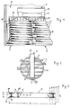
- FIG. 1 shows a section of a packing in a mass and heat exchange column, in which rings offset in the drawing plane are shown, while cut rings are omitted for reasons of clarity.
- FIG. 2 shows a partial plan view of the package from FIG. 1.
- FIG. 3 shows an embodiment of a packing body for the packing of Fig. 1st
- the packing bodies 4 are in the form of an annular hollow cylinder formed, the wall 6 of the hollow cylinder, which is a substantially has uniform wall thickness, all around with a concave outer side 7 and a convex inner side 8 is provided. Furthermore, the ratio of Outside diameter D to the height H of the hollow cylinder so large that the packing body 4 when pouring into a column 1 on the column bottom or one Layer of similar packing bodies 4 a flat position, such as it is shown in Fig. 1 takes.
- the ratio of outer diameter D the height H of the hollow cylinder is preferably between about 6: 1 and 10: 1.
- Such a packing 2 shows a random arrangement of the packing body 4 in each layer 3, wherein 4 more or less large distances between the individual packing bodies are present, individual packing bodies 4 but also point by point are lying, however, the packing 2 is arranged in the direction of the column axis.
- the inwardly curved wall 6 of the packing body 4 gives it sufficient strength and also serves to make a packing body 4 practically not at an angle or vertically in a horizontal package 4 clamp and thus at least in sections the training can prevent from layers 3, but in such a position in the unstable There would be equilibrium, and therefore further spread or fall Packing body 4 in the horizontal position according to the stable balance knock over.
- the wall 6 is expediently in the form of a circular cutout and in particular semicircular, but are also partially oval, for example Concavities possible.
- the inwardly curved wall 6 also brings about a corresponding increase in surface area, which is reduced to the pressure loss and to the Effectiveness and capacity increases.
- the inwardly curved wall 6 also leads to the liquid Phase drains away without the formation of fluid accumulations, so that the residence time the liquid phase in the pack 2 is correspondingly low.
- polymerizations can be carried out in column 1 can be avoided.
- the liquid phase in Suspension or other registered solids are not retained.
- the gaseous phase always flows in the axial direction of the column 1 from bottom to top and thus essentially in the axial direction of the individual packing bodies 4, which pressure difference between the area adjacent to the outside 7 and the area adjacent to the inside 8 cause, wherein the static pressure p 1 on the outside 7 is greater than the static pressure p 2 on the inside 8 (similar to the wing of an aircraft).
- a negative pressure This leads to increased gas turbulence and thus to a corresponding cross-mixing of the gaseous phase, especially since each individual packing body 4 is slightly offset from the adjacent one above and below it.
- the wall thickness of the wall 6 can for example be between 0.2 and 5.0 mm, while outer diameter D is usually in the range between 10 and 300 mm can be selected.
- the minimum of the ratio between Column and packing body diameter without loss of effectiveness about 4.6: 1 compared to a minimum of 8 to 12: 1 for standard, unordered packs, so that, in particular in the case of laboratory devices, packing bodies 4 with a relatively large size Diameter D can be used without disadvantages.
- packing bodies 4 with a smaller diameter D In the case of packing bodies 4 with a smaller diameter D, it is observed that these are partly on the column walls in a vertical or inclined position support. In the case of columns 1 with a smaller column diameter, where normally a lot of liquid flows down the column wall, advantageous be used by this in the liquid from the column wall direct the inside of the column. Packing bodies 4 can also be used for this purpose set up accordingly along the column wall, as shown in Fig. 1 is.
- the packing body 4 can be made of different materials be made of metal such as carbon steel, stainless steel, titanium, copper, Brass, aluminum or the like, which is expediently cold worked, or from thermoplastic material such as polypropylene, polyvinyl chloride, polyethylene or the like or made of ceramic, rubber or glass.
- the starting material used for the production can have a rough structure before, during or after shaping, for example with training normally not from the liquid Phase flooded gas passage openings 9 (FIG. 3) or the like, and / or with a fine structure in the form of grooves, elevations, depressions, small holes or the like be provided, the attachment of these structures of Art the shape used for the packing body 4 depends. He can also Packing body 4 made of a woven material, such as a wire mesh will.
- the ends of the profile section bent into a circular ring can, however also connected to each other for example by riveting, soldering, gluing, etc. be.
- the packing body 4 Due to the outwardly concave wall 6, the packing body 4 has two circumferential edges 11, one of which is set back somewhat from the other can be, i.e. that the diameter of the two edges 11 is slightly different are, so that the packing body 4 falls into the flat lying Position is additionally favored.
- the difference in diameter be so large that the projection of the center of gravity of the packing body 4 in its essentially vertical position on a base outside of it Stand area is.
- the liquid distributor 5 comprises in the illustrated embodiment a feed trough 12 for the liquid phase, which results in distribution troughs 13 overflows.
- the distribution channels 13 have a number of bottom arranged Outlet lines 14 with outlet openings 15.
- the outlet lines 14 are arranged in groups so that their outlet openings 15 on a circle corresponding to a packing body located below 4 of the top layer 3 of the pack 2 are arranged. This will make the Liquid emerging from the outlet openings 15 is directed onto the packing body 4 the top layer 3 abandoned and cannot be an indefinite one Free path through the pack 2 as a beam.
- the packing body 4 of the top layer 3 can be connected so that the top layer 3 of the pack 2 together with the liquid distributor 5 is used in the column 1.
- the top layer 3 of the pack 2 can also be made from one another connected packing bodies 4 exist, expediently under each Outlet opening 15 a packing body 4 of the first layer 3 is arranged.
- the top layer 3 forming a unit can simultaneously hold down for pack 2 against lifting pack 2 if excessive Form gas pollution.
- the liquid distributor 5 as such or together with the top layer 3 can form the hold-down, or both can Be part of the hold-down device.
- Packing bodies 4 with a correspondingly small diameter can the outlet openings 15 or the outlet lines 14 usually do not grouped together, but it is useful if at least each packing body 4 is assigned an outlet opening 15, which of the liquid phase it dispenses onto this packing body 4 of the top layer 3 gives up.
Landscapes
- Chemical & Material Sciences (AREA)
- Physics & Mathematics (AREA)
- Thermal Sciences (AREA)
- Organic Chemistry (AREA)
- Chemical Kinetics & Catalysis (AREA)
- Physical Or Chemical Processes And Apparatus (AREA)
- Vaporization, Distillation, Condensation, Sublimation, And Cold Traps (AREA)
- Devices For Use In Laboratory Experiments (AREA)
Description
Claims (15)
- Packung (2) für eine Stoff- und Wärmeaustauschkolonne (1), in welcher eine gasförmige und eine flüssige Phase miteinander in Kontakt gebracht werden, umfassend eine Vielzahl von gleichen Packungskörpern (4), die im wesentlichen von der Form eines kreisförmigen Hohlzylinders sind, dessen Wandung (6) umlaufend nach außen hin konkav und nach innen hin konvex unter Ausbildung von zwei äußeren umlaufenden Rändern (11) ist und bei dem das Verhältnis von Außendurchmesser (D) zur Höhe (H) groß ist, dadurch gekennzeichnet, daß die Packung (2) aus einer Vielzahl von übereinander angeordneten Lagen (3) von flachliegenden, in jeder Lage (3) zufällig verteilten, innen einen von hineinragenden Bauteilen freien Durchtrittsquerschnitt aufweisenden Packungskörpern (4) besteht, die ein Verhältnis von Außendurchmesser (D) zur Höhe (H) von etwa 6:1 bis etwa 10:1 besitzen.
- Packung nach Anspruch 1, dadurch gekennzeichnet, daß bei den Packungskörpern (4) der Durchmesser eines umlaufenden Randes (11) etwas kleiner als der des anderen umlaufenden Randes (11) ist.
- Packung nach Anspruch 1 oder 2, dadurch gekennzeichnet, daß sich an der Kolonneninnenwand abstützende, vertikal oder schräg gestellte Packungskörper (4) zum Umlenken von an der Kolonneninnenwand herabströmender flüssiger Phase in das Kolonneninnere befinden.
- Packung nach einem der Ansprüche 1 bis 3, dadurch gekennzeichnet, daß die Packungskörper (4) eine Oberflächenstrukturierung zur Verbesserung der Flüssigkeitsverteilung hierauf aufweisen.
- Packung nach einem der Ansprüche 1 bis 4, dadurch gekennzeichnet, daß die Wandung (6) der Packungskörper (4) mit Gasdurchtrittsöffnungen (9) versehen ist.
- Packung nach einem der Ansprüche 1 bis 5, dadurch gekennzeichnet, daß die Packungskörper (4) aus einem Metall durch Kaltverformung hergestellt sind.
- Packung nach Anspruch 6, dadurch gekennzeichnet, daß die Packungskörper (4) aus einem bandförmigen Abschnitt unter Belassung eines schmalen Zwischenraums (10) zwischen den Bandenden geformt sind.
- Packung nach einem der Ansprüche 1 bis 7, dadurch gekennzeichnet, daß die oberste Lage (3) in einer vorbestimmten Anordnung zu einem darüber befindlichen Flüssigkeitsverteiler (5) angeordnet ist.
- Packung nach Anspruch 8, dadurch gekennzeichnet, daß der Flüssigkeitsverteiler (5) Auslauföffnungen (15) aufweist, von denen wenigstens jeweils eine einem Packungskörper (4) der obersten Lage (3) der Packung (2) zugeordnet ist.
- Packung nach Anspruch 9, dadurch gekennzeichnet, daß der Flüssigkeitsverteiler (5) mit einer Vielzahl von Gruppen von kreisförmig angeordneten Auslauföffnungen (15) versehen ist, welche Gruppen sich jeweils oberhalb von einem zugeordneten Packungkörper (4) der obersten Lage (3) derart befinden, daß die aus den Auslauföffnungen (15) austretende Flüssigkeit auf die Packungskörper (4) der obersten Lage (3) trifft.
- Packung nach einem der Ansprüche 8 bis 10, dadurch gekennzeichnet, daß die Packungskörper (4) der obersten Lage (3) mit dem Flüssigkeitsverteiler (5) verbunden sind.
- Packung nach einem der Ansprüche 8 bis 11, dadurch gekennzeichnet, daß die Packungskörper (4) der obersten Lage (3) untereinander verbunden sind.
- Packung nach Anspruch 11 oder 12, dadurch gekennzeichnet, daß der Flüssigkeitsverteiler (5) und/oder die eine Einheit bildende oberste Lage (3) Teil eines Niederhalters sind oder diesen bilden.
- Packung nach einem der Ansprüche 1 bis 13, dadurch gekennzeichnet, daß über der obersten Lage (3) von Packungskörpern (4) ein Flüssigkeitsverteiler (5) mit einer Zuführrinne (12), davon ausgehenden Verteilerrinnen (13) sowie von den Verteilerrinnen (13) ausgehenden, Auslauföffnungen (15) aufweisenden Austrittsleitungen (14), die jeweils gruppenweise in einem Kreis korrespondierend zu einem darunter befindlichen Packungskörper (4) der obersten Lage (3) angeordnet sind, vorgesehen ist.
- Packung nach Anspruch 14, dadurch gekennzeichnet, daß eine Lage (3) von nebeneinander flach liegend angeordneten Packungskörpern (4) mit dem Flüssigkeitsverteiler (5) verbunden ist.
Applications Claiming Priority (3)
| Application Number | Priority Date | Filing Date | Title |
|---|---|---|---|
| BR8804209 | 1988-08-11 | ||
| BR8804209A BR8804209A (pt) | 1988-08-11 | 1988-08-11 | Recheio desordenado |
| PCT/EP1989/000928 WO1990001368A1 (de) | 1988-08-11 | 1989-08-05 | Packung für eine stoff- und wärmeaustauschkolonne |
Publications (2)
| Publication Number | Publication Date |
|---|---|
| EP0396647A1 EP0396647A1 (de) | 1990-11-14 |
| EP0396647B1 true EP0396647B1 (de) | 1998-10-21 |
Family
ID=4045403
Family Applications (1)
| Application Number | Title | Priority Date | Filing Date |
|---|---|---|---|
| EP89908971A Expired - Lifetime EP0396647B1 (de) | 1988-08-11 | 1989-08-05 | Packung für eine stoff- und wärmeaustauschkolonne |
Country Status (8)
| Country | Link |
|---|---|
| EP (1) | EP0396647B1 (de) |
| JP (1) | JPH03500384A (de) |
| AU (1) | AU617516B2 (de) |
| BR (1) | BR8804209A (de) |
| CA (1) | CA1333470C (de) |
| DE (1) | DE58909845D1 (de) |
| MX (1) | MX172894B (de) |
| WO (1) | WO1990001368A1 (de) |
Families Citing this family (1)
| Publication number | Priority date | Publication date | Assignee | Title |
|---|---|---|---|---|
| DE102004027996A1 (de) * | 2004-06-09 | 2005-12-29 | Julius Montz Gmbh | Packungen und Füllkörper für Wärme- und Stoffaustausch |
Family Cites Families (4)
| Publication number | Priority date | Publication date | Assignee | Title |
|---|---|---|---|---|
| DE2310434C2 (de) * | 1970-12-18 | 1985-02-28 | Mass Transfer Ltd., Kendal, Westmorland | Füllkörper für Austausch- und Kontaktkolonnen |
| GB1427712A (en) * | 1972-02-28 | 1976-03-10 | Mass Transfer Ltd | Fluid-fluid contact apparatus |
| GB1385672A (en) * | 1970-12-18 | 1975-02-26 | Mass Transfer Ltd | Fluid-fluid contact apparatus |
| GB8412927D0 (en) * | 1984-05-21 | 1984-06-27 | Mass Transfer Ltd | Packing elements |
-
1988
- 1988-08-11 BR BR8804209A patent/BR8804209A/pt not_active Application Discontinuation
-
1989
- 1989-08-05 AU AU40418/89A patent/AU617516B2/en not_active Ceased
- 1989-08-05 JP JP1508284A patent/JPH03500384A/ja active Pending
- 1989-08-05 WO PCT/EP1989/000928 patent/WO1990001368A1/de not_active Ceased
- 1989-08-05 EP EP89908971A patent/EP0396647B1/de not_active Expired - Lifetime
- 1989-08-05 DE DE58909845T patent/DE58909845D1/de not_active Expired - Fee Related
- 1989-08-10 CA CA000607954A patent/CA1333470C/en not_active Expired - Fee Related
-
1994
- 1994-01-19 MX MX9417158A patent/MX172894B/es unknown
Also Published As
| Publication number | Publication date |
|---|---|
| WO1990001368A1 (de) | 1990-02-22 |
| BR8804209A (pt) | 1988-11-29 |
| CA1333470C (en) | 1994-12-13 |
| AU617516B2 (en) | 1991-11-28 |
| AU4041889A (en) | 1990-03-05 |
| MX172894B (es) | 1994-01-19 |
| DE58909845D1 (de) | 1998-11-26 |
| JPH03500384A (ja) | 1991-01-31 |
| EP0396647A1 (de) | 1990-11-14 |
Similar Documents
| Publication | Publication Date | Title |
|---|---|---|
| DE69409802T2 (de) | Kolonnenboden vergrösserter Kapazität mit mehreren Ablaufvorrichtungen | |
| DE69032706T2 (de) | Prozesskolonne | |
| DE3783880T2 (de) | Strukturierte kolonnenpackung. | |
| DE2943687C2 (de) | Trogartige Vorrichtung zum Sammeln und Verteilen der Flüssigkeit für eine Gegenstromkolonne | |
| EP1038562B1 (de) | Vorrichtung zum Sammeln und Verteilen von Flüssigkeit in einer Kolonne | |
| DE3118836A1 (de) | Fluessigkeitsverteiler fuer fuellkoerper-kolonnen | |
| EP1261404B1 (de) | Verfahren zum Betreiben eines Flüssigkeitsverteilers | |
| DE69412578T2 (de) | Hochleistungswanne für gas-flüssigkeitskontaktvorrichtung | |
| DE1944420B2 (de) | Geschlossener reaktor zur verteilung von abwaertsstroemenden fluessigkeiten | |
| DE112004002124B4 (de) | Rieselfilm-Entgasungsvorrichtung mit Gitterrosten | |
| EP0221095B1 (de) | Wirbelpackung und verfahren zu deren herstellung | |
| DE69203344T2 (de) | Füllkörper und verfahren zu seiner herstellung. | |
| DE2642683A1 (de) | Fluessigkeitsverteiler fuer rohrbuendeltauscher | |
| EP1417015B1 (de) | Kolonnenboden | |
| EP1182416A2 (de) | Innenberipptes Wärmeaustauschrohr mit versetzt angeordneten Rippen unterschiedlicher Höhe | |
| EP3572760A1 (de) | Packung für eine wärme- und/oder stoffübertragung | |
| DE2845804A1 (de) | Fuellkoerper fuer vorrichtungen zum inberuehrungbringen von gasen und fluessigkeiten | |
| DE1519612C3 (de) | Siebboden für Destillier- bzw. Rektifiziersäulen | |
| DE69101968T2 (de) | Kolonnenpackung mit Leitvorrichtungen. | |
| EP0925109A1 (de) | Einbauten für stoffaustauschkolonnen | |
| WO2017194203A1 (de) | Flüssigkeitssammeleinrichtung, stoffaustauschkolonne und verfahren zum herstellen einer derartigen flüssigkeitssammeleinrichtung | |
| EP0396647B1 (de) | Packung für eine stoff- und wärmeaustauschkolonne | |
| EP0718240B1 (de) | Füllkörper und Verfahren zur Herstellung desselben | |
| EP3426369B1 (de) | Packungsanordnung, stoffaustauschkolonne und verfahren | |
| EP0111941B1 (de) | Boden für Destillier- und/oder Absorptionskolonnen |
Legal Events
| Date | Code | Title | Description |
|---|---|---|---|
| PUAI | Public reference made under article 153(3) epc to a published international application that has entered the european phase |
Free format text: ORIGINAL CODE: 0009012 |
|
| 17P | Request for examination filed |
Effective date: 19900428 |
|
| AK | Designated contracting states |
Kind code of ref document: A1 Designated state(s): AT BE CH DE FR GB IT LI LU NL SE |
|
| RBV | Designated contracting states (corrected) |
Designated state(s): CH DE FR GB IT LI NL |
|
| 17Q | First examination report despatched |
Effective date: 19910805 |
|
| GRAG | Despatch of communication of intention to grant |
Free format text: ORIGINAL CODE: EPIDOS AGRA |
|
| GRAG | Despatch of communication of intention to grant |
Free format text: ORIGINAL CODE: EPIDOS AGRA |
|
| GRAH | Despatch of communication of intention to grant a patent |
Free format text: ORIGINAL CODE: EPIDOS IGRA |
|
| GRAH | Despatch of communication of intention to grant a patent |
Free format text: ORIGINAL CODE: EPIDOS IGRA |
|
| GRAA | (expected) grant |
Free format text: ORIGINAL CODE: 0009210 |
|
| AK | Designated contracting states |
Kind code of ref document: B1 Designated state(s): CH DE FR GB IT LI NL |
|
| REG | Reference to a national code |
Ref country code: CH Ref legal event code: EP |
|
| REF | Corresponds to: |
Ref document number: 58909845 Country of ref document: DE Date of ref document: 19981126 |
|
| ET | Fr: translation filed | ||
| ITF | It: translation for a ep patent filed | ||
| ITF | It: translation for a ep patent filed | ||
| REG | Reference to a national code |
Ref country code: CH Ref legal event code: NV Representative=s name: SULZER MANAGEMENT AG |
|
| GBT | Gb: translation of ep patent filed (gb section 77(6)(a)/1977) |
Effective date: 19990122 |
|
| PGFP | Annual fee paid to national office [announced via postgrant information from national office to epo] |
Ref country code: NL Payment date: 19990719 Year of fee payment: 11 Ref country code: CH Payment date: 19990719 Year of fee payment: 11 |
|
| PLBE | No opposition filed within time limit |
Free format text: ORIGINAL CODE: 0009261 |
|
| STAA | Information on the status of an ep patent application or granted ep patent |
Free format text: STATUS: NO OPPOSITION FILED WITHIN TIME LIMIT |
|
| 26N | No opposition filed | ||
| PGFP | Annual fee paid to national office [announced via postgrant information from national office to epo] |
Ref country code: GB Payment date: 20000717 Year of fee payment: 12 |
|
| PGFP | Annual fee paid to national office [announced via postgrant information from national office to epo] |
Ref country code: FR Payment date: 20000801 Year of fee payment: 12 |
|
| PGFP | Annual fee paid to national office [announced via postgrant information from national office to epo] |
Ref country code: DE Payment date: 20000802 Year of fee payment: 12 |
|
| PG25 | Lapsed in a contracting state [announced via postgrant information from national office to epo] |
Ref country code: LI Free format text: LAPSE BECAUSE OF NON-PAYMENT OF DUE FEES Effective date: 20000831 Ref country code: CH Free format text: LAPSE BECAUSE OF NON-PAYMENT OF DUE FEES Effective date: 20000831 |
|
| PG25 | Lapsed in a contracting state [announced via postgrant information from national office to epo] |
Ref country code: NL Free format text: LAPSE BECAUSE OF NON-PAYMENT OF DUE FEES Effective date: 20010301 |
|
| REG | Reference to a national code |
Ref country code: CH Ref legal event code: PL |
|
| NLV4 | Nl: lapsed or anulled due to non-payment of the annual fee |
Effective date: 20010301 |
|
| PG25 | Lapsed in a contracting state [announced via postgrant information from national office to epo] |
Ref country code: GB Free format text: LAPSE BECAUSE OF NON-PAYMENT OF DUE FEES Effective date: 20010805 |
|
| GBPC | Gb: european patent ceased through non-payment of renewal fee |
Effective date: 20010805 |
|
| PG25 | Lapsed in a contracting state [announced via postgrant information from national office to epo] |
Ref country code: FR Free format text: LAPSE BECAUSE OF NON-PAYMENT OF DUE FEES Effective date: 20020430 |
|
| PG25 | Lapsed in a contracting state [announced via postgrant information from national office to epo] |
Ref country code: DE Free format text: LAPSE BECAUSE OF NON-PAYMENT OF DUE FEES Effective date: 20020501 |
|
| REG | Reference to a national code |
Ref country code: FR Ref legal event code: ST |
|
| PG25 | Lapsed in a contracting state [announced via postgrant information from national office to epo] |
Ref country code: IT Free format text: LAPSE BECAUSE OF NON-PAYMENT OF DUE FEES;WARNING: LAPSES OF ITALIAN PATENTS WITH EFFECTIVE DATE BEFORE 2007 MAY HAVE OCCURRED AT ANY TIME BEFORE 2007. THE CORRECT EFFECTIVE DATE MAY BE DIFFERENT FROM THE ONE RECORDED. Effective date: 20050805 |