EP0396992A2 - Freilaufkupplung vom Rollenlagertyp - Google Patents
Freilaufkupplung vom Rollenlagertyp Download PDFInfo
- Publication number
- EP0396992A2 EP0396992A2 EP90108161A EP90108161A EP0396992A2 EP 0396992 A2 EP0396992 A2 EP 0396992A2 EP 90108161 A EP90108161 A EP 90108161A EP 90108161 A EP90108161 A EP 90108161A EP 0396992 A2 EP0396992 A2 EP 0396992A2
- Authority
- EP
- European Patent Office
- Prior art keywords
- rotation body
- rotation
- rolling
- bodies
- raceways
- Prior art date
- Legal status (The legal status is an assumption and is not a legal conclusion. Google has not performed a legal analysis and makes no representation as to the accuracy of the status listed.)
- Granted
Links
Images





Classifications
-
- F—MECHANICAL ENGINEERING; LIGHTING; HEATING; WEAPONS; BLASTING
- F16—ENGINEERING ELEMENTS AND UNITS; GENERAL MEASURES FOR PRODUCING AND MAINTAINING EFFECTIVE FUNCTIONING OF MACHINES OR INSTALLATIONS; THERMAL INSULATION IN GENERAL
- F16D—COUPLINGS FOR TRANSMITTING ROTATION; CLUTCHES; BRAKES
- F16D41/00—Freewheels or freewheel clutches
- F16D41/06—Freewheels or freewheel clutches with intermediate wedging coupling members between an inner and an outer surface
- F16D41/061—Freewheels or freewheel clutches with intermediate wedging coupling members between an inner and an outer surface the intermediate members wedging by movement having an axial component
-
- F—MECHANICAL ENGINEERING; LIGHTING; HEATING; WEAPONS; BLASTING
- F16—ENGINEERING ELEMENTS AND UNITS; GENERAL MEASURES FOR PRODUCING AND MAINTAINING EFFECTIVE FUNCTIONING OF MACHINES OR INSTALLATIONS; THERMAL INSULATION IN GENERAL
- F16D—COUPLINGS FOR TRANSMITTING ROTATION; CLUTCHES; BRAKES
- F16D15/00—Clutches with wedging balls or rollers or with other wedgeable separate clutching members
Definitions
- the present invention relates to a rolling-contact bearing type clutch which functions as a one-way clutch rotatable only in one direction side.
- the one-way clutch wherein cylindrical rollers 3 are arranged in the raceway track between the outer and inner rings 1 and 2, and the inner raceway surface of the outer ring 2 is formed into saw-like cams to bring the inner and outer rings 1 and 2 into clutch condition in reverse rotation by the cylindrical rollers 3 engaged with the cam surface 2c on the outer ring 2, or the other one-way clutch wherein both raceway surfaces of the inner and outer rings are cylindrical, and cam-like sprags are arranged between the inner and outer rings 1 and 2 in place of the cylindrical rollers of the above example, to have each sprag engaged with the raceway surfaces in reverse rotation by spring force.
- cams provided in the one-way clutches according to the prior art pose manufacturing difficulties for material, heat treatment and machining accuracy. Such conditions, when calculating Herts' stress in the design of the allowable surface pressure, forces selection of undesirable values of parameters.
- the rollers since the inner and outer rings of the one-way clutch are respectively formed into a conical surface, the rollers may be brought into a line contact with either the inner raceway or the outer raceway, but not with both at the same time, thus causing unstable rotation of the rollers, resulting in an extremely high surface pressure of the contact portions which fail to be in line contact.
- the first to fourth inventions intend to provide rolling-contact bearing type clutches which can have smooth free rotation taking advantage of rolling-contact bearing, a large rated loading, an increased service life, and a stable operation as clutch, as well as eliminate the need for supporting bearings.
- the fifth and sixth inventions intend to provide rolling-contact bearing type clutches which can further have a simple configuration easy for application to input/output systems.
- the seventh invention intends to provide a rolling-contact bearing type clutch which can have a further enhanced performance in the free rotation.
- the eighth and ninth inventions intend to provide rolling-contact bearing type clutches which can be used in an input/output system whose axial displacement cannot be allowed.
- a rolling-contact bearing type clutch is characterized by an inner rotation body, an outer rotation body, a plurality of intermediate rotation bodies and energizing means; the inner rotation body being provided with an inner raceway surface of mono-hyperboloid 10 of revolution about one axis line, and the outer rotation body being provided with an outer raceway surface of mono-hyperboloid of revolution about the above axis line; the inner raceway surface and the outer raceway surface facing each other to form a combination of raceways; the intermediate rotation bodies of cylindrical rolling surface being disposed in the circumferential direction of the raceways with their center axes slanting at a predetermined angle to a section including the same axis for the inner and outer rotation bodies, the surface of each intermediate rotation body being in line contact with the inner and outer raceway surfaces, the energizing means energizing either the inner rotation body or the outer rotation body in the axis line direction to narrow the distance of the raceways, and
- a rolling-contact bearing type clutch is characterized by an inner rotation body, an outer rotation body, a plurality of intermediate rotation bodies and energizing means; the inner rotation body being provided with an inner raceway surface of mono-hyperboloid of revolution about one axis line, and the outer rotation body being provided with an outer raceway surface of mono-hyperboloid of revolution about the above axis line; the inner raceway surface and the outer raceway surface facing each other to form a combination of raceways; the intermediate rotation bodies of conical rolling surface being disposed in the circumferential direction of the raceways with their center axes slanting at a predetermined angle to a selection including the same axis for the inner and outer rotation bodies, the surface of each intermediate rotation body being in line contact with the inner and outer raceway surfaces, the energizing means pushing the intermediate rotation bodies from the large diameter side to the small diameter side of the intermediate rotation bodies, and the inner or outer rotation body being provided with an annular member which brings the movement of the intermediate rotation bodies in the
- a rolling-contact bearing type clutch is characterized by an inner rotation body, an outer rotation body, a plurality of intermediate rotation bodies and energizing means; the inner rotation body being provided with an inner raceway surface of cylinder about one axis line, and the outer rotation body being provided with an outer raceway surface of a combined curved surface of a mono-hyperboloid of revolution and an ellipsoid of revolution about the above axis line; the inner raceway surface and the outer raceway surface facing each other to form a combination of raceways; the intermediate rotation bodies of hourglass-shaped rolling surface formed with a partial curve of ellipse rotated about the center axis thereof and with the radial section gradually increased from one end to the other end being disposed in the circumferential direction of the raceways with their center axes slanting at a predetermined angle to a section including the same axis for the inner and outer rotation bodies, the surface of each intermediate rotation body being in line contact with the inner and outer raceway surfaces, the
- a rolling-contact bearing type clutch is characterized by an inner rotation body, an outer rotation body, a plurality of intermediate rotation bodies and energizing means; the outer rotation body being provided with an outer raceway surface of cylinder about one axis line, and the inner rotation body being provided with an inner raceway surface of a combined curved surface of a mono-hyperboloid of revolution and an ellipsoid of revolution about the above axis line; the inner raceway surface and the outer raceway surface facing each other to form a combination of raceways; the intermediate rotation bodies of convex drum-shaped rolling surface formed with a partial curve of ellipse rotated about the center axis thereof and with the radial section gradually increased from one end to the other end being disposed in the circumferential direction of the raceways with their center axes slanting at a predetermined angle to a section including the same axis for the inner and outer rotation bodies, the surface of each intermediate rotation body being in line contact with the inner and outer raceway surfaces,
- the line contact of the intermediate rotation bodies with the inner and outer race way surfaces will provide a uniform load distribution, and an excellent rolling in the free rotation while a sufficient clutch force due to the wedge effect of the rotation bodies in the reverse rotation.
- An automatic alignment force applied to the intermediate rotation bodies can ensure a uniform load distribution for a change in various conditions of the clutch such as deformation, wear and variations of dimensional accuracy.
- the rolling-contact bearing type clutches according to the invention can have a large rated load, a long service life, and a stable operation with smooth free rotation. Further, the clutches function as bearings, thus eliminating the need for additional bearings on the shaft.
- a rolling-contact bearing type clutch according to the fifth invention is the same as the third invention excepting that a rotation shaft is used in place of the inner rotation body in the third invention.
- a rolling-contact bearing type clutch according to the sixth invention is the same as the fourth invention excepting that a mechanical element is used in place of the outer rotation body in the fourth invention.
- the rotation shaft or the mechanical element can be used as the inner or outer rotation body, the configuration of a system including the rolling-contact bearing clutch can be simplified, thus achieving a low cost and a wide application.
- a rolling-contact bearing type clutch according to the seventh invention is the same as the first to sixth inventions excepting that each of the intermediate rotation bodies is divided into two or more in the center axis direction.
- the seventh invention can provide an excellent skewness in the fixed raceway, and a reduced rolling resistance, thus enhancing the performance in the free rotation.
- a rolling-contact bearing type clutch is the same as the first to seventh inventions excepting that:
- An input/output rotation body is provided to transmit a torque.
- the input/output rotation body is located at one side of the outer rotation body, and mounted at a predetermined axial position away from the inner rotation body on the same side of the inner rotation body so as to freely rotate relatively to the inner rotation body via a bearing, and is connected to the outer rotation body through torque transmission means for transmitting the torque to the outer rotation body, and the energizing means is provided between the input/output rotation body and the outer rotation body to energize the outer rotation body in the axial direction and to narrow the distance between the raceway surfaces.
- a rolling-contact bearing type clutch is the same as the first to seventh inventions excepting that:
- An input/output rotation body is provided to transmit a torque.
- the input/output rotation body is located at one side of the inner rotation body, and mounted at a predetermined axial position away from the outer rotation body on the same side of the outer rotation body so as to freely rotate relatively to the outer rotation body via a bearing, and is connected to the inner rotation body through torque transmission means for transmitting the torque to the inner rotation body, and the energizing means is provided between the input/output rotation body and the inner rotation body to energize the inner rotation body in the axial direction and to narrow the distance between the raceway surfaces.
- Fig. 1 is a view showing a rolling-contact bearing type clutch according to the present invention
- Fig. 2 is a perspective view showing the rollers and internal parts of the embodiment in Fig. 1:
- An inner ring 1 corresponding to the inner rotation body in the previous description is mounted on a shaft 4 movably by a key engagement 5.
- An outer ring 2 corresponding to the other rotation body is disposed facing the inner ring 1 to form a combination of raceways 9.
- a plurality of rollers 3 corresponding to the intermediate rotation body are, as shown in Fig. 2, disposed between the raceways 9 slanting to a plane including a center shaft 6 (axis line) of the inner ring 1 at angle of ⁇ (e.g., 15 degree).
- the inner ring 1 is pushed by the outer ring 2 via a combination of a plate spring 7 and a spring retainer ring 8 corresponding to the energizing means, to a direction to narrow the space of the raceways 9 (from right to left in the drawing).
- a flange 10 corresponding to the ring member which brings the movement of the rollers 3 in the axial direction to widen the distance of the raceways 9 to a stop is formed on the inner ring 1 at the end thereof.
- the rollers 3 will rotate to the left to advance the inner ring 1 to the right direction against an energizing force of the plate spring 7 while guided by the outer ring raceway surface 2a to enlarge the space of the raceways 9.
- an action of tapered screw will be produced between the inner and outer rings 1 and 2 via the rollers 3.
- the action will cause a right direction advancement of the inner ring 1 relative to the outer ring 2 based on the principle of the screw advancement to enlarge the space of the raceways 9.
- the inner ring 1 can be freely rotated without causing a wedge action of the rollers 3 between the raceways 9.
- the flange 10 is disposed at the end of the inner ring 1 to prevent the rollers 3 from advancing the inner ring 1 too far in the right direction and from disengaging from the inner ring 1 in the left direction.
- the rollers 3 will rotate to the right not to advance but to retreat the inner ring 1 to the left direction.
- the compression force of the plate spring 7 will move the inner ring 1 to the left relative to the outer ring 2 to narrow the space of the raceways 9.
- the action will cause the rollers 3 to be locked between the raceways 9 to produce a wedge effect.
- the inner ring 1 and the outer ring 2 can be clutched as soon as the shaft 1 starts the reversal rotation.
- the pushing portion 2b at the right end side of the outer ring 2 may be connected to the outer ring 2 itself, and further two pieces of the rolling-contact bearing type clutches may be arranged facing each other to make two or more rows.
- the inner ring 1 is movable in the axial direction, but not the inner ring 1 but the outer ring 2 may be movable.
- a thrust bearing mounted in place of the spring retainer ring 8 portion can have a further enhanced free rotation.
- rollers 3 are arranged on the inner ring 1 slanting to a section including the axis 6 thereof by an angle of ⁇ , and the rollers 3 is retained in place by a retainer 11 to keep off each another.
- This configuration can prevent adjacent rollers 3 rotating in a same direction from running against each other with a relative tangential speed in an opposite direction, resulting in a smooth rotation of the rollers 3 and a smooth revolution thereof around the inner ring 1.
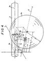
- Figs. 3 to 5 are explanatory drawings to determine the raceway surface shapes in a case of cylindrical rollers 3;
- Fig. 3 is a perspective view of X-Y-Z coordinates, in which a roller 3 is so placed that the axis 3a passes through the Y axis a distance F away from the origin 0, parallel to the X-Z plane, slanting to the X-Y plane at an angle ⁇ .
- the X axis represents the common axis 6 of the inner and outer rings 1 and 2.
- the section 3b of the roller 3 shows a section of the roller 3 cut by a parallel plane to the X-Z plane passing the X axis at an arbitrary position x.
- Points Uc and U′c are respectively intersections with the X axis and the X-Z plane of the perpendiculars from the center Pc of the cross section to the X axis and the X-Z plane.
- the line 3a′ passing the origin 0 and the point U′c is a projected line of the roller axis 3a to the X-Z plane, forming an angle ⁇ with the X axis.
- Fig. 4 is a drawing explaining how the rings 1 and 2 come into contact with the roller 3 arranged as above.
- PiUi and PoUo are respectively distances from the points Pi and Po to the X axis
- distances OUi and OUo from the origin point 0 are respectively the X axis coordinates of the points Pi and Po. Therefore, designating OUi , OUo , PiUi and PoUo as xi, so, yi and yo, functions F (xi, yi) and F (xo, yo) represent the curved surface shape of the raceways 1a and 2a of the inner and outer rings.
- Fig. 5 is an enlarged view showing related portions to determine these relation.
- Fig. 6 shows an embodiment wherein the cylindrical shape of the roller 3 in Fig. 1 is replaced with a conical shape. Since the generating line of a conical roller is a straight line, the inner and outer raceway surfaces become mono-hyperboloids of revolution similar to those of cylindrical roller. Conical roller-contact bearing type clutches may have similar constructions and functions to those of the cylindrical ones, but the conical one can have a further enhanced rolling.
- the conical type embodiment shown in Fig. 6 has a flange 10 at the end of the inner ring 1 to prevent the inner ring 1 from moving out of the inner ring 1 in the axial direction. But, since the conical shape of the roller 3 can generate a wedge action only by a slight movement of the roller 3, the flange 10 may be eliminated when the inner ring 1 is fixed on the shaft in the axial direction.
- Such conical rolling-contact bearing type clutches may be used in two or more rows.
- Figs. 7 to 8 are perspective views showing other embodiments having a cylindrical inner or outer ring raceway surface: The basic construction and functions of these embodiment are similar to those of the embodiment shown in Fig. 1, thus omitting description of the common features.
- rollers 3 of hourglass or convex drum shape with sectional areas extended from one end to the other end, even if the inner ring 1 (in Fig. 7, the shaft 4 also serves as the inner ring) and the outer ring 2 do not move in the axial direction, the rollers 3 will advance to right (when the rollers 3 rotate clockwise viewing from the right in the drawing) or retreat to the lfet due to the rotation of the inner and outer rings 1 and 2, thus providing a free rotation, or clutch action due to the wedge action generated by the rollers 3.
- this embodiment can eliminate the need for a member (flange 10 in Fig.1) which brings the axial movement of the roller 3 in this direction to a halt.
- the rollers 3 can freely advance without causing wedge action, thus providing a free rotation of the inner and outer rings.
- a guide ring 12 is provided to guide the rolling.
- Such a rolling-contact bearing type clutch as having a cylindrical inner or outer ring raceway surface can directly use the inner ring for the shaft, or the outer ring for a mechanical element such as gear, pulley and flywheel which needs clutch function and whose inner surface can be used, or a hollow shaft, thus achieving a simplified construction and a low cost as well as an easy installation and a wider application as a clutch.
- the inner and outer rings of the type of clutch does not move in their axial direction, thus making the design of a driving system easier.
- the type of clutch may also be designed to have a similar configuration to the one of the embodiment shown in Fig. 1 in which the inner and outer rings can be moved. In this case, in the free rotation or the clutch condition, the function of the inner and outer rings as tapered screw via the rollers can be also used.
- roller-contact bearing type clutches as described above may be used in two or more rows.
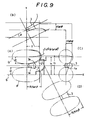
- Fig. 9 is an explanatory drawing to determine the outer ring raceway surface shape, and (A) is a front view, (B) a plan view, (C) a side view and (D) is a side view viewing from oblique direction ;
- the line of contact must be an intersecting line on the outer surface of the inner ring 1 when the inner ring 1 is cut by a plane slanted at the angle of ⁇ from the plane including the axis 6 of the inner ring 1, and the shape of the line is a part of an ellipse.
- the surface shape of the roller 3 becomes like a hourglass which is formed by a rotation of a partial ellipse directing the outside. Designating the radius of the inner ring as R, the minor axis length of the ellipse is R and the major is R / sin ⁇ .
- the equation (6) expresses an equation for an ellipse Q, same as the ellipse P on the axis line 6. Therefore, from the equation (8), the shape of the outer ring raceway surface 2a becomes a rotation surface about the center axis 6 of a combined curve of hyperbolic y coordinate u′ and ellipsoidal y coordinate v, that is, a combined surface of a mono-hyperboloid of revolution and an ellipsoid of revolution.
- Fig. 10 is an explanatory drawing to determine the inner ring raceway surface shape
- the inner ring raceway (1a) shape can be determined also in the similar manner to the above described.
- the surface shape of the roller 3 becomes a convex drum formed by a revolution of a partial ellipse.
- the inner ring raceway surface 1a is a revolution of a combined curve of hyperboloid and ellipse.
- Fig. 1 and Figs. 6 to 8 all has a one-piece roller (3) assembly, which may be divided into two or more subassemblies in the axial direction.
- This arrangement can enhance the performance in the free rotation. More specifically, this type of clutch can reduce rolling resistance, has an enhanced skewness, and increase the adaptability for alignment and machining accuracy.
- Figs. 11 and 12 are sectional views showing other embodiments: Rolling-contact bearing type clutches which use cylindrical rollers, and can be used with an input/output side fixed in the axial direction.
- a space between the inner and outer rings 1 and 2 forms a raceway 9 for the cylindrical rollers 3 retained therein by a retainer 11.
- an input/output rotation body such as a housing 14 which transmits input torque is disposed via a thrust bearing 13 which functions as the bearing of the clutch.
- the housing 14 is mounted fixedly to the inner ring 1 in the axial direction and rotatably by the thrust bearing 13 built therein. Further, the housing 14 is so connected to the outer ring 2 as to rotate integrally therewith through a torque transmission pin 15 (Fig. 11), or an involute spline 16 (Fig. 12) or a ball spline (not shown).
- a pre-compressed spring such as a coil spring 7′ or a plate spring 7 is provided between the housing 14 and the outer ring 2 as energizing means, to apply a pre-force to the outer ring 2.
- these embodiments can be generally used as a rolling-contact bearing type clutch when no axial displacement of an input side and output side is allowed.
- Figs. 11 and 12 shows examples in which the housing is disposed to the outer ring side, but the housing may be connected to the inner ring (1) side through involution spline 16 so that the torque is transmitted to the inner ring 1 as shown in Fig. 13.
- the rollers are intentionally slanted to the plane including the same axis line 6 of the inner and outer rings, so that, in the relative free rotation between the inner and outer rings, the rollers 3 can rotate maintaining a stable line contact with the inner and outer ring raceway surfaces while maintaining a stable revolution about the same axis of the inner and outer rings, thereby obtaining an excellent load distribution.
- the rollers 3 can change their attitude, so that all the rollers 3 would participate in the carriage of the load, thus achieving an automatically unified load distribution. Therefore, the clutch with a general machining accuracy can realize a calculated load distribution, thus obtaining an even clutch operation.
- rollers 3 functions as a rolling member of a bearing by their rotation and revolution in the free rotation, while as a sprag member of the clutch operation by the action of the energizing means and their automatic aligning action in the reverse rotation (clutch).
- the inner ring 1 or outer ring 2 or roller 3 may have an axial displacement, but pose no challenge to the clutch operation, thus eliminating the need for addition of the wall thickness of the inner and outer rings to ensure the rigidity for the inner and outer forces or for paying a special preventive consideration for wear, thereby realizing a light weight compact clutch assembly.
- the rolling-contact bearing type clutch according to the invention has a circular radial section of the rollers as seen in the general roller bearings, facilitating the calculation of the allowable surface pressure by using the same equation and factors as in the general bearings.
Landscapes
- Engineering & Computer Science (AREA)
- General Engineering & Computer Science (AREA)
- Mechanical Engineering (AREA)
- Rolling Contact Bearings (AREA)
Applications Claiming Priority (4)
| Application Number | Priority Date | Filing Date | Title |
|---|---|---|---|
| JP113621/89 | 1989-05-08 | ||
| JP11362189 | 1989-05-08 | ||
| JP328418/89 | 1989-12-20 | ||
| JP1328418A JPH0374641A (ja) | 1989-05-08 | 1989-12-20 | ころがり軸受クラッチ |
Publications (3)
| Publication Number | Publication Date |
|---|---|
| EP0396992A2 true EP0396992A2 (de) | 1990-11-14 |
| EP0396992A3 EP0396992A3 (de) | 1991-01-09 |
| EP0396992B1 EP0396992B1 (de) | 1995-08-23 |
Family
ID=26452568
Family Applications (1)
| Application Number | Title | Priority Date | Filing Date |
|---|---|---|---|
| EP90108161A Expired - Lifetime EP0396992B1 (de) | 1989-05-08 | 1990-04-28 | Freilaufkupplung vom Rollenlagertyp |
Country Status (6)
| Country | Link |
|---|---|
| US (1) | US5035309A (de) |
| EP (1) | EP0396992B1 (de) |
| CN (1) | CN1047372A (de) |
| AU (1) | AU643207B2 (de) |
| CA (1) | CA2015041A1 (de) |
| DE (1) | DE69021769T2 (de) |
Cited By (5)
| Publication number | Priority date | Publication date | Assignee | Title |
|---|---|---|---|---|
| GB2265192A (en) * | 1992-03-21 | 1993-09-22 | Schaeffler Waelzlager Kg | Locking element freewheel |
| EP0551515A4 (de) * | 1991-08-13 | 1994-01-19 | Nobuo Takata | |
| EP0544916A4 (en) * | 1991-06-03 | 1994-08-24 | Nobuo Takata | Variable transmission |
| EP0529079A4 (en) * | 1991-03-18 | 1995-06-14 | Nobuo Takata | Torque absorbing device |
| KR20190106357A (ko) * | 2018-03-09 | 2019-09-18 | 박용식 | 회전전달장치 |
Families Citing this family (30)
| Publication number | Priority date | Publication date | Assignee | Title |
|---|---|---|---|---|
| US5211273A (en) * | 1986-01-22 | 1993-05-18 | Hybo Science, Inc. | Axial thrust clutch/bearing/freewheel |
| JP2938966B2 (ja) * | 1990-11-21 | 1999-08-25 | テイエチケー株式会社 | ころがり軸受クラッチ |
| US5238461A (en) * | 1991-02-11 | 1993-08-24 | Gotman Alexander S | Reactionlless differential rotary driver having optimized output torques |
| WO1993000521A1 (en) * | 1991-06-20 | 1993-01-07 | Hybo Science, Inc. | Self containing clutch |
| WO1993000519A1 (en) * | 1991-06-20 | 1993-01-07 | Hybo Science, Inc. | Safety coupling for in-line rotatable shafts |
| WO1993011373A1 (en) * | 1991-11-25 | 1993-06-10 | Hybo Science, Inc. | Improvements in helical, bevel and worm gear arrangements |
| US5411218A (en) * | 1992-07-02 | 1995-05-02 | Daiwa Seiko, Inc. | Bearing type drag mechanism for fishing reel |
| US5392887A (en) * | 1993-12-27 | 1995-02-28 | Introl Company, L.P. | Bi-directional tapered roller clutch |
| WO1995018315A1 (en) * | 1993-12-27 | 1995-07-06 | Introl Company, L.P. | Bi-directional tapered roller clutch |
| JP3443483B2 (ja) * | 1995-06-12 | 2003-09-02 | 株式会社荏原製作所 | 転がり軸受クラッチ |
| JPH08338503A (ja) * | 1995-06-12 | 1996-12-24 | Ebara Corp | 動力伝達装置 |
| US6121705A (en) * | 1996-12-31 | 2000-09-19 | Hoong; Fong Chean | Alternating pole AC motor/generator with two inner rotating rotors and an external static stator |
| JPH11141577A (ja) * | 1997-11-05 | 1999-05-25 | Nsk Warner Kk | 一方向クラッチ |
| JP2000186752A (ja) | 1998-12-22 | 2000-07-04 | Kenji Mimura | 回転摩擦装置 |
| CA2293075A1 (en) * | 1998-12-28 | 2000-06-28 | Kenji Mimura | Friction resistance generator |
| JP2000297860A (ja) | 1999-02-12 | 2000-10-24 | Nsk Ltd | オルタネータ用ローラクラッチ内蔵型プーリ装置 |
| JP2000240461A (ja) | 1999-02-23 | 2000-09-05 | Nsk Ltd | オルタネータ用一方向クラッチ内蔵型プーリ装置とオルタネータ駆動用無端ベルトの鳴き防止方法 |
| JP3364603B2 (ja) * | 1999-06-25 | 2003-01-08 | 建治 三村 | 摩擦クラッチ及びこれを用いた自動車の自動変速機及び自動車の無段変速機並びに自動車の動力分配装置及び自動二輪車の動力伝達装置 |
| WO2001027485A1 (en) * | 1999-10-13 | 2001-04-19 | Preload International Limited | Roller clutch |
| DE10123082C1 (de) * | 2001-05-11 | 2003-01-16 | Friedrich-W Von Hackewitz | Wälzkörperfreilauf |
| US6886678B2 (en) * | 2003-05-02 | 2005-05-03 | Siemens Vdo Automotive Corporation | Clutch assembly for electric motors to prevent back drive |
| DE102004057126A1 (de) * | 2004-11-26 | 2006-06-08 | Zf Friedrichshafen Ag | Einrichtung zur Reduzierung der Axialbewegung der Hauptwellenräder bei einem Getriebe mit zumindest zwei Vorgelegewellen |
| DE102006018695B4 (de) | 2005-05-19 | 2018-03-01 | Schaeffler Technologies AG & Co. KG | Freilauf |
| EP1724487B1 (de) * | 2005-05-19 | 2009-08-12 | LuK Lamellen und Kupplungsbau Beteiligungs KG | Freilauf |
| EP1801460B1 (de) * | 2005-12-21 | 2010-04-14 | LuK Lamellen und Kupplungsbau Beteiligungs KG | Antriebseinheit mit einem inneren Antriebselement und einem äusseren Antriebselement |
| JP5897951B2 (ja) * | 2012-03-28 | 2016-04-06 | 株式会社ユニバンス | クラッチ装置 |
| US9994432B2 (en) * | 2016-03-16 | 2018-06-12 | Goodrich Corporation | Hoist cable drum with an integral ball spline and internal gear ring |
| CN107521622B (zh) * | 2017-08-22 | 2019-03-15 | 池仁淼 | 一种新型可离合、平移和刹闸的工业转动机构 |
| CN108035971A (zh) * | 2018-01-15 | 2018-05-15 | 海南冠星电机有限公司 | 单向轴承 |
| JP6912666B2 (ja) * | 2018-06-20 | 2021-08-04 | ジーケーエヌ オートモーティブ リミテッド | テーパローラを備えた低ヒステリシスのカム機構 |
Family Cites Families (13)
| Publication number | Priority date | Publication date | Assignee | Title |
|---|---|---|---|---|
| US1469991A (en) * | 1923-10-09 | Means for preventing displacement of rollers-in | ||
| US1670197A (en) * | 1924-03-24 | 1928-05-15 | Humfrey Sandberg Co Ltd | Free-wheel ratchet device |
| GB248183A (en) * | 1925-03-12 | 1926-03-04 | John Charles Willis Humfrey | Improvements relating to clutch devices |
| US1834843A (en) * | 1929-01-17 | 1931-12-01 | Humfreysandberg Company Ltd | Free-wheel clutch with skew rollers |
| US1955880A (en) * | 1930-12-02 | 1934-04-24 | Packard Motor Car Co | Clutch mechanism |
| US1929782A (en) * | 1931-12-09 | 1933-10-10 | New Departure Mfg Co | Clutch |
| DE1145446B (de) * | 1958-06-10 | 1963-03-14 | Daimler Benz Ag | Als Freilaufkupplung ausgebildetes Radialkugellager |
| JPS5121093B1 (de) * | 1968-03-29 | 1976-06-30 | ||
| JPS513853B2 (de) * | 1972-06-14 | 1976-02-06 | ||
| JPS5852092A (ja) * | 1981-09-11 | 1983-03-28 | 株式会社東京タツノ | 給油装置 |
| SE449908B (sv) * | 1984-09-26 | 1987-05-25 | Skf Ab | Rullager der rullarna och lopbanorna har krokta lengdsnittsprofiler |
| GB8501822D0 (en) * | 1985-01-24 | 1985-02-27 | Castens R R | Clutches |
| EP0312656A1 (de) * | 1987-10-22 | 1989-04-26 | Hybo Science, Inc. | Kupplungen |
-
1990
- 1990-04-16 US US07/509,668 patent/US5035309A/en not_active Expired - Lifetime
- 1990-04-20 CA CA002015041A patent/CA2015041A1/en not_active Abandoned
- 1990-04-28 EP EP90108161A patent/EP0396992B1/de not_active Expired - Lifetime
- 1990-04-28 DE DE69021769T patent/DE69021769T2/de not_active Expired - Fee Related
- 1990-04-30 AU AU54576/90A patent/AU643207B2/en not_active Ceased
- 1990-05-08 CN CN90102750A patent/CN1047372A/zh active Pending
Cited By (6)
| Publication number | Priority date | Publication date | Assignee | Title |
|---|---|---|---|---|
| EP0529079A4 (en) * | 1991-03-18 | 1995-06-14 | Nobuo Takata | Torque absorbing device |
| EP0544916A4 (en) * | 1991-06-03 | 1994-08-24 | Nobuo Takata | Variable transmission |
| EP0551515A4 (de) * | 1991-08-13 | 1994-01-19 | Nobuo Takata | |
| GB2265192A (en) * | 1992-03-21 | 1993-09-22 | Schaeffler Waelzlager Kg | Locking element freewheel |
| GB2265192B (en) * | 1992-03-21 | 1995-12-13 | Schaeffler Waelzlager Kg | Locking element freewheel |
| KR20190106357A (ko) * | 2018-03-09 | 2019-09-18 | 박용식 | 회전전달장치 |
Also Published As
| Publication number | Publication date |
|---|---|
| EP0396992A3 (de) | 1991-01-09 |
| CN1047372A (zh) | 1990-11-28 |
| AU643207B2 (en) | 1993-11-11 |
| EP0396992B1 (de) | 1995-08-23 |
| CA2015041A1 (en) | 1990-11-08 |
| DE69021769D1 (de) | 1995-09-28 |
| AU5457690A (en) | 1990-11-08 |
| US5035309A (en) | 1991-07-30 |
| DE69021769T2 (de) | 1996-04-11 |
Similar Documents
| Publication | Publication Date | Title |
|---|---|---|
| US5035309A (en) | Rolling-contact bearing type clutch | |
| US5328012A (en) | Rolling-contact bearing type clutch | |
| US3800927A (en) | One way clutch | |
| US3599767A (en) | Reversible sprag clutch | |
| EP1138969B1 (de) | Einrichtung zur übertragung einer Drehbewegung mit einer Einweckupplung | |
| US5381879A (en) | Torque absorber | |
| US3732957A (en) | Free wheel device | |
| EP0551516B1 (de) | Rollenlager | |
| US3743066A (en) | Free wheel drive | |
| US4354585A (en) | Overrunning clutch shiftable to free wheeling | |
| US5309781A (en) | Stepless speed change gear | |
| US6513633B2 (en) | Rotation transmitting device incorporating one-way clutch therein | |
| EP0190017A1 (de) | Kupplungen | |
| US3187863A (en) | One-way clutch | |
| JP2002276749A (ja) | 電動式駆動装置 | |
| JP2001116065A (ja) | ローラクラッチ | |
| RU2043549C1 (ru) | Обгонная муфта | |
| EP3859189A1 (de) | Stromübertragungsvorrichtung | |
| JP2857220B2 (ja) | ころがりころ軸受 | |
| JPH09264342A (ja) | 1方向クラッチ | |
| JP3570794B2 (ja) | 1方向クラッチ | |
| JPS62215160A (ja) | 牽引ロ−ラ変速機 | |
| CA2093648A1 (en) | Antifriction roller bearing | |
| JP3031942B2 (ja) | トルクリミッタ | |
| EP0551515A1 (de) | Kupplung zum absorbieren von drehmoment-schwankungen |
Legal Events
| Date | Code | Title | Description |
|---|---|---|---|
| PUAI | Public reference made under article 153(3) epc to a published international application that has entered the european phase |
Free format text: ORIGINAL CODE: 0009012 |
|
| AK | Designated contracting states |
Kind code of ref document: A2 Designated state(s): CH DE FR GB LI SE |
|
| PUAL | Search report despatched |
Free format text: ORIGINAL CODE: 0009013 |
|
| AK | Designated contracting states |
Kind code of ref document: A3 Designated state(s): CH DE FR GB LI SE |
|
| 17P | Request for examination filed |
Effective date: 19901222 |
|
| 17Q | First examination report despatched |
Effective date: 19920121 |
|
| RIN1 | Information on inventor provided before grant (corrected) |
Inventor name: TAKATA, NOBUO |
|
| RAP1 | Party data changed (applicant data changed or rights of an application transferred) |
Owner name: THK MENT RESEARCH CO., LTD. |
|
| RIN1 | Information on inventor provided before grant (corrected) |
Inventor name: TAKATA, NOBUO |
|
| GRAA | (expected) grant |
Free format text: ORIGINAL CODE: 0009210 |
|
| AK | Designated contracting states |
Kind code of ref document: B1 Designated state(s): CH DE FR GB LI SE |
|
| PG25 | Lapsed in a contracting state [announced via postgrant information from national office to epo] |
Ref country code: CH Effective date: 19950823 Ref country code: LI Effective date: 19950823 |
|
| REF | Corresponds to: |
Ref document number: 69021769 Country of ref document: DE Date of ref document: 19950928 |
|
| ET | Fr: translation filed | ||
| REG | Reference to a national code |
Ref country code: CH Ref legal event code: PL |
|
| PG25 | Lapsed in a contracting state [announced via postgrant information from national office to epo] |
Ref country code: SE Effective date: 19951123 |
|
| PLBE | No opposition filed within time limit |
Free format text: ORIGINAL CODE: 0009261 |
|
| STAA | Information on the status of an ep patent application or granted ep patent |
Free format text: STATUS: NO OPPOSITION FILED WITHIN TIME LIMIT |
|
| 26N | No opposition filed | ||
| REG | Reference to a national code |
Ref country code: FR Ref legal event code: TP |
|
| REG | Reference to a national code |
Ref country code: GB Ref legal event code: 732E |
|
| PGFP | Annual fee paid to national office [announced via postgrant information from national office to epo] |
Ref country code: FR Payment date: 20000411 Year of fee payment: 11 |
|
| PG25 | Lapsed in a contracting state [announced via postgrant information from national office to epo] |
Ref country code: FR Free format text: THE PATENT HAS BEEN ANNULLED BY A DECISION OF A NATIONAL AUTHORITY Effective date: 20010430 |
|
| REG | Reference to a national code |
Ref country code: GB Ref legal event code: IF02 |
|
| REG | Reference to a national code |
Ref country code: FR Ref legal event code: ST |
|
| PGFP | Annual fee paid to national office [announced via postgrant information from national office to epo] |
Ref country code: DE Payment date: 20020502 Year of fee payment: 13 |
|
| PG25 | Lapsed in a contracting state [announced via postgrant information from national office to epo] |
Ref country code: DE Free format text: LAPSE BECAUSE OF NON-PAYMENT OF DUE FEES Effective date: 20031101 |
|
| PGFP | Annual fee paid to national office [announced via postgrant information from national office to epo] |
Ref country code: GB Payment date: 20090422 Year of fee payment: 20 |
|
| REG | Reference to a national code |
Ref country code: GB Ref legal event code: PE20 Expiry date: 20100427 |
|
| PG25 | Lapsed in a contracting state [announced via postgrant information from national office to epo] |
Ref country code: GB Free format text: LAPSE BECAUSE OF EXPIRATION OF PROTECTION Effective date: 20100427 |