EP0397318B1 - Source d'énergie pour l'exploration sismique - Google Patents
Source d'énergie pour l'exploration sismique Download PDFInfo
- Publication number
- EP0397318B1 EP0397318B1 EP19900303552 EP90303552A EP0397318B1 EP 0397318 B1 EP0397318 B1 EP 0397318B1 EP 19900303552 EP19900303552 EP 19900303552 EP 90303552 A EP90303552 A EP 90303552A EP 0397318 B1 EP0397318 B1 EP 0397318B1
- Authority
- EP
- European Patent Office
- Prior art keywords
- sonde
- wellbore
- piezoelectric element
- fluid
- seismic energy
- Prior art date
- Legal status (The legal status is an assumption and is not a legal conclusion. Google has not performed a legal analysis and makes no representation as to the accuracy of the status listed.)
- Expired - Lifetime
Links
- 239000012530 fluid Substances 0.000 claims description 50
- 238000006243 chemical reaction Methods 0.000 claims description 42
- 230000033001 locomotion Effects 0.000 claims description 19
- 230000015572 biosynthetic process Effects 0.000 claims description 15
- 238000005755 formation reaction Methods 0.000 claims description 15
- 230000004044 response Effects 0.000 claims description 9
- 239000000463 material Substances 0.000 claims description 6
- 239000012528 membrane Substances 0.000 claims description 5
- QSHDDOUJBYECFT-UHFFFAOYSA-N mercury Chemical compound [Hg] QSHDDOUJBYECFT-UHFFFAOYSA-N 0.000 claims description 4
- 229910052753 mercury Inorganic materials 0.000 claims description 4
- 238000000034 method Methods 0.000 claims description 3
- 238000006073 displacement reaction Methods 0.000 description 7
- 230000008602 contraction Effects 0.000 description 6
- 238000004891 communication Methods 0.000 description 4
- 230000008901 benefit Effects 0.000 description 3
- 230000007246 mechanism Effects 0.000 description 3
- 230000036316 preload Effects 0.000 description 3
- 230000001133 acceleration Effects 0.000 description 2
- 230000000712 assembly Effects 0.000 description 2
- 238000000429 assembly Methods 0.000 description 2
- 239000000919 ceramic Substances 0.000 description 2
- 239000004020 conductor Substances 0.000 description 2
- 230000000694 effects Effects 0.000 description 2
- 229910052451 lead zirconate titanate Inorganic materials 0.000 description 2
- 230000000737 periodic effect Effects 0.000 description 2
- 230000003252 repetitive effect Effects 0.000 description 2
- 238000007789 sealing Methods 0.000 description 2
- 230000006978 adaptation Effects 0.000 description 1
- 230000004075 alteration Effects 0.000 description 1
- 230000005540 biological transmission Effects 0.000 description 1
- 229910010293 ceramic material Inorganic materials 0.000 description 1
- 230000006835 compression Effects 0.000 description 1
- 238000007906 compression Methods 0.000 description 1
- 238000011109 contamination Methods 0.000 description 1
- 238000013461 design Methods 0.000 description 1
- 238000005553 drilling Methods 0.000 description 1
- 230000005684 electric field Effects 0.000 description 1
- 230000004907 flux Effects 0.000 description 1
- 239000010720 hydraulic oil Substances 0.000 description 1
- 230000010365 information processing Effects 0.000 description 1
- 238000003780 insertion Methods 0.000 description 1
- 230000037431 insertion Effects 0.000 description 1
- HFGPZNIAWCZYJU-UHFFFAOYSA-N lead zirconate titanate Chemical compound [O-2].[O-2].[O-2].[O-2].[O-2].[Ti+4].[Zr+4].[Pb+2] HFGPZNIAWCZYJU-UHFFFAOYSA-N 0.000 description 1
- 239000007788 liquid Substances 0.000 description 1
- 239000003921 oil Substances 0.000 description 1
- 230000010349 pulsation Effects 0.000 description 1
- 238000005086 pumping Methods 0.000 description 1
- 230000009467 reduction Effects 0.000 description 1
- 229920002994 synthetic fiber Polymers 0.000 description 1
- 238000003325 tomography Methods 0.000 description 1
- 238000012546 transfer Methods 0.000 description 1
- 235000012431 wafers Nutrition 0.000 description 1
- 238000004804 winding Methods 0.000 description 1
Images



Classifications
-
- G—PHYSICS
- G01—MEASURING; TESTING
- G01V—GEOPHYSICS; GRAVITATIONAL MEASUREMENTS; DETECTING MASSES OR OBJECTS; TAGS
- G01V1/00—Seismology; Seismic or acoustic prospecting or detecting
- G01V1/02—Generating seismic energy
- G01V1/143—Generating seismic energy using mechanical driving means, e.g. motor driven shaft
- G01V1/145—Generating seismic energy using mechanical driving means, e.g. motor driven shaft by deforming or displacing surfaces, e.g. by mechanically driven vibroseis™
-
- B—PERFORMING OPERATIONS; TRANSPORTING
- B06—GENERATING OR TRANSMITTING MECHANICAL VIBRATIONS IN GENERAL
- B06B—METHODS OR APPARATUS FOR GENERATING OR TRANSMITTING MECHANICAL VIBRATIONS OF INFRASONIC, SONIC, OR ULTRASONIC FREQUENCY, e.g. FOR PERFORMING MECHANICAL WORK IN GENERAL
- B06B1/00—Methods or apparatus for generating mechanical vibrations of infrasonic, sonic, or ultrasonic frequency
- B06B1/02—Methods or apparatus for generating mechanical vibrations of infrasonic, sonic, or ultrasonic frequency making use of electrical energy
- B06B1/06—Methods or apparatus for generating mechanical vibrations of infrasonic, sonic, or ultrasonic frequency making use of electrical energy operating with piezoelectric effect or with electrostriction
- B06B1/0607—Methods or apparatus for generating mechanical vibrations of infrasonic, sonic, or ultrasonic frequency making use of electrical energy operating with piezoelectric effect or with electrostriction using multiple elements
- B06B1/0611—Methods or apparatus for generating mechanical vibrations of infrasonic, sonic, or ultrasonic frequency making use of electrical energy operating with piezoelectric effect or with electrostriction using multiple elements in a pile
Definitions
- the present invention relates to a seismic energy source apparatus especially, but not exclusively, for downhole use.
- VSP Very Seismic Profiling
- RVSP Reverse Vertical Seismic Profiling
- a seismic energy source apparatus for imparting seismic energy into earth formations, said seismic energy source comprising: a hydraulic system containing a substantially incompressible fluid and having at least one power piston and at least one drive piston wherein small movements in relation to a power piston generate substantially larger movements in relation to a drive piston; at least one piezoelectric element adapted to elongate and contract in response to the application of an appropriate electrical signal, the or each said piezoelectric element being coupled to a power piston to transmit movement thereto; and means for imparting seismic energy into earth formations in response to movement of the or each drive piston.
- the apparatus comprises a sonde adapted to be lowered into a wellbore; clamping means for selectively clamping said sonde within said wellbore at a selected depth; said hydraulic system and piezoelectric element(s) being housed in said sonde; and wherein said means for imparting seismic energy comprises a reaction mass coupled to a drive piston, wherein application of an appropriate electrical signal to said piezoelectric element will result in a substantial movement of said reaction mass to impart seismic energy into said earth formations surrounding said wellbore.
- the apparatus comprises a sonde adapted to be lowered into a wellbore; packer means for selectively isolating said sonde within a closed volume of fluid within said wellbore; the hydraulic system and the piezoelectric element being housed within said sonde; and wherein the apparatus also includes a second volume of substantially incompressible fluid coupled to said drive piston and disposed within said sonde, separated from said fluid within said closed volume of said wellbore by a flexible membrane, wherein application of an appropriate electrical signal to said piezoelectric element will result in the application of fluid pressure energy to said fluid within said wellbore through said flexible membrane.
- a hydraulic system is employed to amplify the longitudinal displacement resulting from application of voltage to a stack of piezoelectric elements.
- the amplified displacement is utilized to accelerate a reaction mass, for example, to create a reaction force for the generation of seismic energy.
- reciprocating, torsional or radial displacements, motions and forces may be generated with the reaction waves.
- the piezoelectric seismic vibrator of the present invention is highly efficient and requires little electrical current, as piezoelectric materials respond to an applied voltage, not current, in contrast to magnetostrictive devices which require large currents to generate the required flux densities via transformer windings.
- One preferred embodiment of the present invention also possesses significant advantages over servo valve controlled hydraulic systems of the prior art, in that the prior art devices produce a non-linear response to the control or pilot signal. Also, of course, a servo valve cannot open, close or shift position instantaneously, nor can large amounts of hydraulic fluid travel into and out of a power chamber of a vibrator rapidly to move a reaction mass. In addition, there are significant energy losses associated with the use of servo valves and the long, convoluted and restricted hydraulic fluid passages associated therewith.
- the piezoelectric vibrator of the present invention requires no servo valves or fluid lines, and the response of the piezoelectric element stacks is essentially instantaneous.
- Source 20 may be lowered into the wellbore 10 via wireline 22.
- Source 20 comprises a housing 24 which contains a clamping assembly 26 and a seismic energy assembly 28.
- the illustrated clamping assembly 26 is one example of such devices as known in the art, and its design does not in itself comprise a portion of the present invention except insofar as it is necessary to employ such an apparatus to effectively couple source 20 to the wellbore wall for transmission of seismic energy pulses from seismic energy assembly 28 to the surrounding formation 30.
- Clamping assembly 26 preferably includes moveable pad 32 and stationary pad 34 for contacting the wall of wellbore 10.
- Pad 32 is disposed at the end of a pair of actuator rods 36, having hydraulic pistons 38 disposed at their inner ends.
- Pistons 38 are located within cylinders 40 in housing 24, and are preferably biased inwardly to a retracted position by spring means 42, which may comprise coil, Belleville or other springs known in the art.
- Cylinders 40 are filled at their inner ends with a noncompressible hydraulic fluid and are in communication with three-way solenoid valve 44 via actuation passage 46. Solenoid valve 44 is in turn also in communication with bleed passage 48 and reservoir passage 50. Bleed passage 48 leads to the exterior of housing 24, and reservoir passage 50 leads from hydraulic fluid reservoir 52 to solenoid valve 44. Fluid in reservoir 52 is pressurized by reservoir piston 54, the lower side of which is acted upon by high-pressure N2 in reservoir 56 , which is charged to an appropriate pressure level at the surface before source 20 is placed in the borehole.
- Solenoid valve 44 is initially set in its first position, which isolates both actuation passage 46 and bleed passage 48 from reservoir passage 50 , before source 20 is run into the wellbore 10 . Movable pad 32 is retracted and maintained in retraction by spring means 42 . After source 20 reaches the desired wellbore location for generation of seismic energy, solenoid valve 46 is commanded to its second position by control module 58 , which is powered by wireline 22 via internal conductors 60 , shown in broken lines.
- clamping assembly 26 is set forth generally as one exemplary system of this type, and that other systems known in the art could serve an equivalent function.
- a magnetically operated system could be employed, or a screw-jack type system driven by an electric motor; alternatively, a simple mechanically, hydraulically or explosively set packer- slip assembly such as is well known in the downhole tool art might be employed.
- seismic assembly 28 comprises a reciprocal inner reaction mass 70 which reciprocates in chamber 72 of housing 22 . Travel of the reaction mass 70 is limited by inwardly-extending annular flange 74 which contacts impact bearings 76 and 78 which are disposed at the upper and lower ends of vertically extending annular recess 80 in the outer wall of reaction mass 70 . Rotation of reaction mass 70 is prohibited by means of key 81 which extends inwardly from the wall of chamber 72 into vertical slot 82 in the outer wall of reaction mass 70 .
- drive pistons 84 and 84' of cross-sectional areas A Disposed at the upper and lower ends of chamber 72 are drive pistons 84 and 84' of cross-sectional areas A, which extend downwardly and upwardly, respectively into apertures 86 and 86' in the wall of reaction mass 70 .
- annular seals may be utilized to effect a fluid tight seal therebetween.
- Drive chambers 88 and 88' containing a high bulk modulus fluid with high temperature stability, preferably mercury, are located at the upper and lower ends of reaction mass 70 , in communication with drive pistons 84 and 84' , via apertures 86 and 86' .
- drive chambers 88 and 88' are defined by movable power pistons 90 and 90' , which are of greater diameter and significantly greater cross-sectional areas than the ends of drive pistons 84 and 84' .
- movable power pistons 90 and 90' Located below and above power pistons 90 and 90' respectively,lie two stacks of piezoelectric elements, 92 and 92' , the innermost ends of which abut bulkhead 94 at the middle of reaction mass 70 .
- Piezoelectric element stacks 92 and 92' comprise a plurality of thin circular, square, rectangular or other polyhedral shaped elements or discs of a poled piezoelectric material such as lead meta-niobate, ceramic lead zirconate titanate (PZT) ceramic or other suitable material, stacked vertically.
- Conductor set 96 leads from control module 58 to each piezoelectric element stack 92 and 92' , in parallel, to supply a voltage thereto. The polarity of the voltage across each stack is opposite to that applied to the other stack. As a result, when a voltage is applied, one stack will expand in proportion to the electrical field, while the other stack will contract at the same time and in a linear fashion.
- each stack undergoes time varying extension and contraction.
- stack 92 extends in length, it applies an upwardly directional force to power piston 90 , and so upon the fluid in drive chamber 88 .
- the attempted reduction by power piston 90 of the volume of chamber 88 results in reaction mass 70 being pushed away (downward) from drive piston 84 so that the volume of chamber 88 can remain constant, given the incompressible nature of the fluid in the chamber.
- Preloading may be accomplished in several ways however, the simplest way may be to provide a threaded plug (not shown) in the wall of reaction mass 70 adjacent chambers 88 and 88' , so that such plugs may be driven inwardly to an appropriate point to induce compression of stacks 92 and 92' via movement of power pistons 90 and 90' .
- drive pistons 84 and 84' may have source adjustable travel with respect to housing 22 , and preload applied in that manner.
- a screw mechanism or hydraulic system may be incorporated within bulkhead 94 to preload from the inner ends of stacks 92 and 92' , the manner of preloading not being critical to the practice of the invention.
- the embodiment of Figure 1 generates seismic energy through longitudinal reciprocation of reaction mass 70 within chamber 72 in response to the extension and contraction of piezoelectric element stacks 92 and 92' .
- the displacement of reaction mass 70 is the total extension of a piezoelectric stack as multiplied by the ratio of the cross-sectional area of power pistons 90 and 90' to the cross-sectional area of drive pistons 84 and 84' .
- piezoelectric stack 92 is capable of a total of 1/4'' (6.4mm) extension when subjected to a selected voltage of the correct polarity, and the area of power piston 90 is eight times the area of drive piston 84 , the displacement of reaction mass 70 will be 8 x 1/4'' (6.4mm), or 2'' (51mm) total.
- a pressure transducer (not shown) may be located in chamber 88 or 88' to sense the force developed by the actuator and used as a feedback signal to control module 52 for phase and amplitude control.
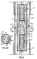
- Figure 2 depicts a second preferred embodiment of the present invention adapted to generate horizontal shear, or S H , waves of seismic energy. Since a suitable deployment means, i.e. wireline, and clamp means have already been disclosed and described with respect to the embodiment of Figure 1 , they have been omitted in Figure 2 ; however, it should be understood that such means would also be employed with the embodiment of Figure 2 .
- a suitable deployment means i.e. wireline, and clamp means
- Seismic energy source 100 includes a housing 102 having associated therewith a plurality of clamps 104 which are extended outwardly therefrom into contact with the wall of wellbore 10 in which source 100 is disposed.
- the means for extending and retracting clamps 104 of which there are preferably three or more equally circumferentially disposed about housing 102 , may be of any of the means discussed previously with respect to Figure 1.
- reaction mass 106 Disposed within housing 102 is reaction mass 106 , which is supported therein by roller, ball or needle bearing assemblies 108 and 108' so as to permit rotation of reaction mass 106 within housing 102 .
- Reaction mass 106 includes upper and lower piezoelectric disc stacks 110 and 110' , which are preferably precompressionally loaded as in the embodiment of Figure 1 , and which bear against power pistons 112 and 112' , the latter defining outer, movable walls of power chambers 114 and 114' , which are filled with a high bulk modulus relatively incompressible fluid, such as mercury.
- Power chambers 114 and 114' are, in turn linked with drive cylinders 116A , 116B , 116C , and 116D by passages 118A , 118B , 118C , and 118D , respectively ( 116B and 118B not being shown as they are located behind 116A and 118A in a plane perpendicular to the drawing Figure 2 ).
- Drive cylinders 116 contain drive pistons 120A , 120B , 120C and 120D which are of cylindrical configuration and in fluid-tight sliding sealing engagement with the walls of cylinders 116.
- Pistons 120 each have a leading face with a cup-shaped notch or recess 121 in the center thereof, into which a torsion rod 122 having a like configured end which extends from housing 102 .
- torsion rods 122 are all in radial plane, and offset from the diameter of reaction mass 106 and housing 102 , and that each rod 122 and its associated drive piston 120 are disposed in linkage recesses 124A , B , C , and D , respectively in reaction mass 106 to permit uninhibited relative movement at the points of contact therebetween.
- the ends of rods 122 or the recesses 121 may comprise a low friction, high wear resistance bearing material to cut friction losses and promote an acceptable cycle life.
- the space 126 between housing 102 and reaction mass 106 may be filled with a suitable liquid, such as hydraulic oil, to promote heat transfer to the surrounding wellbore and to lubricate bearing assemblies 108 and 108' and the points of contact between drive pistons 120 and their associated torsion rods 122 .
- a suitable liquid such as hydraulic oil
- source 100 is activated by application of a suitable periodic voltage of alternating polarities to piezoelectric disc stacks 110 and 110' .
- the polarity of the voltage applied to each stack 110 and 110' may be the same, so that both stacks elongate at the same time and contract at the same time, so as to double the force applied in one rotational direction to the wellbore wall.
- the applied polarities may be opposite, so as to obtain a positive rotational force in each direction.
- Source 100 operates as follows. When a suitable voltage is applied to disc stacks 110 and 110' , assuming the applied polarities are the same, both stacks elongate and drive power pistons 112 and 112' longitudinally inwardly in power chambers 114 and 114' , displacing the fluid therein into passages 116 and then into drive cylinders 118 , where the fluid acts upon drive pistons 120 , moving them outward into linkage recesses and acting upon torsion rods 122 , the contact points therebetween permitting a pivotal motion as pistons 120 extend and reaction mass 106 rotates, due to such extension, in the opposite direction.
- drive pistons 120 , and their associated tension rods 122 may be oriented so that two pistons in one plane drive in one rotational direction, and two in another plane drive in the opposite rotational direction. In such event, opposite polarity voltages would be applied to disc stacks 110 and 110' at the same time, so that one would extend at the same instant the other would contract, thereby providing a positive rotational drive for reaction mass 106 in each direction.
- the acceleration of the reaction mass provides the reaction force which is transmitted through clamps 104 to the wellbore wall and surrounding formation as seismic energy in the form of horizontal shear waves, or S H waves.
- FIG. 3 there is depicted a downhole, fluid pressure energy source which may be implemented with the seismic energy source of the present invention.
- suitable deployment means including a wireline, have already been disclosed and will not be shown herein.
- Fluid pressure energy source 200 is shown disposed within wellbore 10 and isolated within a particular section thereof by means of packers 202 and 202' .
- Packers 202 and 202' each comprise an inflatable or otherwise actuatable packer which may be operated to isolate energy source 200 within a closed volume 204 of borehole fluid in order to maximize the pulse effect.
- energy source 200 includes piezoelectric disc stacks 206 and 206' which are disposed within fluid filled chambers 208 and 208' .
- Fluid filled chambers 208 and 208' are utilized to equalize the pressure on piezoelectric stacks 206 and 206' in the following manner.
- Each fluid filled chamber 208 and 208' is preferably connected to an equalization chamber 210 and 210' respectively, by means of passages 212 and 212' , each of which preferably includes a filter element 214 and 214' which is utilized to prohibit the contamination of fluids therein by borehole fluids.
- Within each equalization chamber 210 and 210' is a piston 216 and 216' which is acted upon by borehole pressure, via passages 218 and 218' . In this manner, the pressure within closed volume 204 acts upon pistons 216 and 216' and thereby pressurizes the fluid within fluid filled chambers 208 and 208' to a pressure equal to that within closed volume 204 .
- piezoelectric stacks 206 and 206' bear against power pistons 220 and 220' , each defining an outer movable wall of power chambers 222 and 222' , which are filled with a high bulk modulus relatively incompressible fluid, such as mercury.
- Power chambers 222 and 222' are in turn linked to drive pistons 224 and 224' , which are of cylindrical configuration and in fluid-tight sliding sealing engagement within the walls of chambers 222 and 222' .
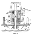
- FIG. 4 there is depicted a surface reciprocating seismic energy source adaptation of the apparatus of the present invention.
- the embodiment depicted in Figure 4 is designed to be operated upon the surface of the earth 300 and to transmit vibrational seismic signals into the earth via base plate 302 .
- the seismic source depicted within Figure 4 in schematic form is preferably a transportable via a vehicle (not shown) which is supported upon vehicle supports 308 and serves to press baseplate 302 against the surface of the earth 300 by means of hold down plate 304 .
- hold down plate 304 is preferably isolated from base plate 302 by means of air bags 306 or other suitable devices.
- the seismic source depicted within Figure 4 includes a plurality of piezoelectric stacks 312A-312D , each of which is electrically coupled to control means 318 .
- Control means 318 is preferably utilized to generate a suitable time varying electrical signal which is coupled to each piezoelectric element stack 312A-312D in order to generate the desired elongation and contraction thereof.
- each piezoelectric element stack bears upon a respective power piston 316A-316D which in accordance with the hydraulic amplifier aspect of the present invention, amplifies the pressure which is brought to bear upon reaction mass 314 .
- Reaction mass 314 is preferably coupled to central shaft 310 having enlarged portion 320 constituting a drive piston.
- the apparatus means in accordance with the teachings of the present application may be utilized to generate a vibrational seismic signal which may be imparted to the surface of the earth via base plate 302.
- the radial compressional energy source 400 depicted within Figure 5 includes a pair of piezoelectric element stacks 406 and 406' which are disposed within fluid filled chambers 408 and 408' .
- fluid filled chambers 408 and 408' are utilized to equalize the pressure on piezoelectric stacks 406 and 406' by means of equalization chambers 410 and 410' respectively.
- multiple additional equalization chambers such as chamber 432 may be provided, each including a piston 434 which is acted upon by the pressure of borehole fluids via aperture 436 .
- the movement of piston 434 acts upon the fluid therein which is then coupled via passage 438 to provide pressure equalization on both sides of power piston 420 .
- radial compressional energy source 400 with reaction mass 402 is identical in concept to the previous embodiments disclosed. That is, the application of a suitable time varying voltage to piezoelectric stabs 406 and 406' will cause a corresponding elongation and contraction thereof, bearing upon power pistons 420 and 420' . The movement of power pistons 420 and 420' within power chambers 422 and 422' will cause a force to be applied to drive pistons 428A and 428B . As is illustrated, drive pistons 428A and 428B are coupled via rods 426A and 426B to cause impact pistons 424A and 424B to compress the inner walls of borehole 10 .
- spring elements 430A and 430B are utilized to bias drive pistons 428A and 428B into a refracted position, thereby facilitating the insertion of rapid compressional source 400 into the borehole.
- spring elements 430A and 430B are utilized to bias drive pistons 428A and 428B into a refracted position, thereby facilitating the insertion of rapid compressional source 400 into the borehole.
- multiple impact pistons may be utilized to generate a radial compressional energy wave outward from the axis of borehole 10 in the manner depicted herein.
Landscapes
- Engineering & Computer Science (AREA)
- Life Sciences & Earth Sciences (AREA)
- Remote Sensing (AREA)
- Physics & Mathematics (AREA)
- Environmental & Geological Engineering (AREA)
- Acoustics & Sound (AREA)
- Mechanical Engineering (AREA)
- Geology (AREA)
- General Life Sciences & Earth Sciences (AREA)
- General Physics & Mathematics (AREA)
- Geophysics (AREA)
- Geophysics And Detection Of Objects (AREA)
- Apparatuses For Generation Of Mechanical Vibrations (AREA)
Claims (11)
- Dispositif (20, 100, 200, 400) formant source d'énergie sismique, destiné à communiquer une énergie sismique dans des formations terrestres, ladite source d'énergie sismique comportant : un dispositif hydraulique contenant un fluide pratiquement incompressible et ayant au moins un piston de puissance (90, 90'; 112, 112'; 220, 220'; 316A à 316D; 420, 420') et au moins un piston d'entraînement (84, 84'; 120A à 120D; 224, 224'; 428A, 428B, 320) dans lequel de petits déplacements du piston de puissance engendrent des déplacements relativement importants du piston d'entraînement; au moins un élément piézoélectrique (92, 92'; 110, 110'; 206, 206'; 312A à 312D; 406, 406') conçu pour s'allonger et se contracter en réponse à l'application d'un signal électrique approprié, le ou chaque élément piézoélectrique étant relié à un piston de puissance pour transmettre un déplacement à celui-ci; et des moyens (26; 228; 302; 424A, 424B) destinés à appliquer une énergie sismique dans des formations terrestres en réponse au déplacement du piston ou de chaque piston d'entraînement.
- Dispositif selon la revendication 1, dans lequel l'élément piézoélectrique ou chaque élément piézoélectrique est constitué d'un empilage de plusieurs disques minces de matériau piézoélectrique.
- Dispositif selon la revendication 1 ou 2, dans lequel l'élément piézoélectrique ou chaque élément piézoélectrique est monté directement sur un piston de puissance.
- Dispositif selon la revendication 1, 2 ou 3, dans lequel l'élément piézoélectrique ou chaque élément piézoélectrique est monté à l'intérieur d'une chambre remplie de fluide (208, 208'; 408, 408') adaptée pour appliquer une pression sur ledit élément piézoélectrique.
- Dispositif selon l'une quelconque des revendications 1 à 4, qui comporte une sonde (24; 102; 402) adaptée pour être abaissée dans un alésage de puits; des moyens de blocage (26; 104) destinés à bloquer de manière sélective ladite sonde à l'intérieur dudit alésage de puits à une profondeur choisie; ledit dispositif hydraulique et le ou lesdits éléments piézoélectriques étant reçus dans ladite sonde; et dans lequel lesdits moyens destinés à appliquer une énergie sismique comportent une masse de réaction (70; 106; 314; 402) accouplée à un piston d'entraînement, dans lequel l'application d'un signal électrique approprié audit élément piézoélectrique entraîne un déplacement important de ladite masse de réaction pour appliquer une énergie sismique dans lesdites formations terrestres entourant ledit alésage de puits.
- Dispositif selon la revendication 5, dans lequel ladite masse de réaction est montée à l'intérieur de ladite sonde de manière soit à se déplacer longitudinalement à l'intérieur de ladite sonde en réponse au déplacement dudit piston d'entraînement, soit à se déplacer en rotation à l'intérieur de ladite sonde en réponse au déplacement dudit piston d'entraînement.
- Dispositif selon la revendication 5 ou 6, dans lequel lesdits moyens de serrage comportent au moins un patin mobile (32, 34) et des moyens (38) pour solliciter ledit patin radialement vers l'extérieur en contact avec ledit alésage de puits, lesdits moyens de sollicitation (38) étant de préférence reliés à un dispositif pneumatique.
- Dispositif selon l'une quelconque des revendications 1 à 4, qui comporte une sonde (24; 102; 402) adaptée pour être abaissée jusque dans un alésage de puits; des moyens (202, 202') formant garniture d'étanchéité pour isoler de manière sélective ladite sonde à l'intérieur d'un volume fermé (204) de fluide situé à l'intérieur dudit alésage de puits; le dispositif hydraulique et l'élément piézoélectrique étant reçus à l'intérieur de ladite sonde; et dans lequel le dispositif comporte également un second volume de fluide pratiquement incompressible associé audit piston d'entraînement et disposé à l'intérieur de ladite sonde en étant séparé dudit fluide situé à l'intérieur dudit volume fermé dudit alésage de puits par une membrane souple (228), dans lequel l'application d'un signal électrique approprié audit élément piézoélectrique entraîne l'application, à travers ladite membrane souple, d'une énergie de pression de fluide vers ledit fluide situé à l'intérieur dudit alésage de puits.
- Dispositif selon la revendication 8, dans lequel il existe deux éléments piézoélectriques (206, 206') agencés longitudinalement à l'intérieur de ladite sonde sur des côtés opposés dudit second volume de fluide pratiquement incompressible.
- Dispositif selon l'une quelconque des revendications 1 à 9, dans lequel ledit fluide pratiquement incompressible et/ou ledit second volume de fluide pratiquement incompressible sont constitués de mercure.
- Procédé de surveillance sismique dans lequel il est utilisé un appareil tel que revendiqué dans l'une quelconque des revendications 1 à 10.
Applications Claiming Priority (2)
| Application Number | Priority Date | Filing Date | Title |
|---|---|---|---|
| US34905889A | 1989-05-08 | 1989-05-08 | |
| US349058 | 1989-05-08 |
Publications (3)
| Publication Number | Publication Date |
|---|---|
| EP0397318A2 EP0397318A2 (fr) | 1990-11-14 |
| EP0397318A3 EP0397318A3 (fr) | 1991-07-31 |
| EP0397318B1 true EP0397318B1 (fr) | 1994-01-05 |
Family
ID=23370742
Family Applications (1)
| Application Number | Title | Priority Date | Filing Date |
|---|---|---|---|
| EP19900303552 Expired - Lifetime EP0397318B1 (fr) | 1989-05-08 | 1990-04-03 | Source d'énergie pour l'exploration sismique |
Country Status (2)
| Country | Link |
|---|---|
| EP (1) | EP0397318B1 (fr) |
| DE (1) | DE69005692T2 (fr) |
Cited By (3)
| Publication number | Priority date | Publication date | Assignee | Title |
|---|---|---|---|---|
| DE102004014722B3 (de) * | 2004-03-25 | 2005-12-29 | Geoforschungszentrum Potsdam | Seismische Quelle und Verfahren zur Erzeugung seismischer Schwingungen |
| DE102005024367A1 (de) * | 2005-05-27 | 2006-11-30 | Geoforschungszentrum Potsdam | Seismische Quelle und Verfahren zur Erzeugung seismischer Scherwellen |
| US7467685B2 (en) | 2004-05-25 | 2008-12-23 | Schlumberger Technology Corporation | Array seismic fluid transducer source |
Families Citing this family (6)
| Publication number | Priority date | Publication date | Assignee | Title |
|---|---|---|---|---|
| FR2658304B1 (fr) * | 1990-02-14 | 1992-08-28 | Schlumberger Prospection | Source sismique de fond et procede de creation d'ondes acoustiques dans un puits de forage. |
| FR2667518B1 (fr) * | 1990-10-08 | 1994-10-14 | Inst Francais Du Petrole | Source vibrante electro-hydraulique utilisable notamment dans des puits. |
| FR2671297A1 (fr) * | 1991-01-09 | 1992-07-10 | Inst Francais Du Petrole | Source vibrante electro-hydraulique de puits. |
| FR2678390B1 (fr) * | 1991-06-27 | 1996-05-15 | Inst Francais Du Petrole | Source vibrante electro-hydraulique de puits avec circuits hydrauliques resonants. |
| GB0424808D0 (en) * | 2004-11-10 | 2004-12-15 | Univ Edinburgh | Improvements to seismic sources |
| US9348042B2 (en) * | 2011-12-27 | 2016-05-24 | Cgg Services Sa | Buried pressurized volumetric source and method |
Family Cites Families (3)
| Publication number | Priority date | Publication date | Assignee | Title |
|---|---|---|---|---|
| FR1605218A (fr) * | 1962-03-22 | 1973-08-31 | ||
| US4671379A (en) * | 1985-09-03 | 1987-06-09 | Petrophysical Services, Inc. | Method and apparatus for generating seismic waves |
| CN1022139C (zh) * | 1986-03-18 | 1993-09-15 | 切夫伦研究公司 | 利用非破坏性井下地震源获得地质结构信息的方法 |
-
1990
- 1990-04-03 DE DE1990605692 patent/DE69005692T2/de not_active Expired - Fee Related
- 1990-04-03 EP EP19900303552 patent/EP0397318B1/fr not_active Expired - Lifetime
Cited By (4)
| Publication number | Priority date | Publication date | Assignee | Title |
|---|---|---|---|---|
| DE102004014722B3 (de) * | 2004-03-25 | 2005-12-29 | Geoforschungszentrum Potsdam | Seismische Quelle und Verfahren zur Erzeugung seismischer Schwingungen |
| US7467685B2 (en) | 2004-05-25 | 2008-12-23 | Schlumberger Technology Corporation | Array seismic fluid transducer source |
| DE102005024367A1 (de) * | 2005-05-27 | 2006-11-30 | Geoforschungszentrum Potsdam | Seismische Quelle und Verfahren zur Erzeugung seismischer Scherwellen |
| DE102005024367B4 (de) * | 2005-05-27 | 2013-08-22 | Helmholtz-Zentrum Potsdam Deutsches GeoForschungsZentrum - GFZ Stiftung des Öffentlichen Rechts des Landes Brandenburg | Seismische Quelle und Verfahren zur Erzeugung seismischer Scherwellen |
Also Published As
| Publication number | Publication date |
|---|---|
| EP0397318A2 (fr) | 1990-11-14 |
| DE69005692D1 (de) | 1994-02-17 |
| EP0397318A3 (fr) | 1991-07-31 |
| DE69005692T2 (de) | 1994-04-28 |
Similar Documents
| Publication | Publication Date | Title |
|---|---|---|
| US5115880A (en) | Piezoelectric seismic vibrator with hydraulic amplifier | |
| US4702343A (en) | Nondestructive downhole seismic vibrator source and processes of utilizing the vibrator to obtain information about geologic formations | |
| US4715470A (en) | Downhole electromagnetic seismic source | |
| AU2005262362B2 (en) | Acoustic telemetry transceiver | |
| US4751688A (en) | Downhole electromagnetic seismic source | |
| EP0485261B1 (fr) | Transducteur acoustique pour puits de forage | |
| EP0213950A2 (fr) | Procédé et dispositif pour générer des ondes sismiques | |
| EP0397318B1 (fr) | Source d'énergie pour l'exploration sismique | |
| US4815557A (en) | Down hole seismographic source | |
| US5080189A (en) | Electro-hydraulic dipole vibrator | |
| US4850449A (en) | Piezoelectric seismic vibration device and method | |
| CA2584264C (fr) | Generateur de signal pour puits de forage | |
| US5109946A (en) | Apparatus for pack-off locking of seismic energy source | |
| CA2999157C (fr) | Un generateur de forme d'onde de pression de fluide et methodes d'utilisation associees | |
| US5069307A (en) | Acoustic signal transmitter for logging tools |
Legal Events
| Date | Code | Title | Description |
|---|---|---|---|
| PUAI | Public reference made under article 153(3) epc to a published international application that has entered the european phase |
Free format text: ORIGINAL CODE: 0009012 |
|
| AK | Designated contracting states |
Kind code of ref document: A2 Designated state(s): DE FR GB |
|
| RAP1 | Party data changed (applicant data changed or rights of an application transferred) |
Owner name: HALLIBURTON GEOPHYSICAL SERVICES, INC. |
|
| PUAL | Search report despatched |
Free format text: ORIGINAL CODE: 0009013 |
|
| AK | Designated contracting states |
Kind code of ref document: A3 Designated state(s): DE FR GB |
|
| 17P | Request for examination filed |
Effective date: 19920120 |
|
| 17Q | First examination report despatched |
Effective date: 19930217 |
|
| GRAA | (expected) grant |
Free format text: ORIGINAL CODE: 0009210 |
|
| AK | Designated contracting states |
Kind code of ref document: B1 Designated state(s): DE FR GB |
|
| REF | Corresponds to: |
Ref document number: 69005692 Country of ref document: DE Date of ref document: 19940217 |
|
| ET | Fr: translation filed | ||
| PLBE | No opposition filed within time limit |
Free format text: ORIGINAL CODE: 0009261 |
|
| STAA | Information on the status of an ep patent application or granted ep patent |
Free format text: STATUS: NO OPPOSITION FILED WITHIN TIME LIMIT |
|
| 26N | No opposition filed | ||
| PGFP | Annual fee paid to national office [announced via postgrant information from national office to epo] |
Ref country code: GB Payment date: 20000317 Year of fee payment: 11 |
|
| PGFP | Annual fee paid to national office [announced via postgrant information from national office to epo] |
Ref country code: FR Payment date: 20000405 Year of fee payment: 11 |
|
| PGFP | Annual fee paid to national office [announced via postgrant information from national office to epo] |
Ref country code: DE Payment date: 20000427 Year of fee payment: 11 |
|
| PG25 | Lapsed in a contracting state [announced via postgrant information from national office to epo] |
Ref country code: GB Free format text: LAPSE BECAUSE OF NON-PAYMENT OF DUE FEES Effective date: 20010403 |
|
| PG25 | Lapsed in a contracting state [announced via postgrant information from national office to epo] |
Ref country code: FR Free format text: THE PATENT HAS BEEN ANNULLED BY A DECISION OF A NATIONAL AUTHORITY Effective date: 20010430 |
|
| GBPC | Gb: european patent ceased through non-payment of renewal fee |
Effective date: 20010403 |
|
| PG25 | Lapsed in a contracting state [announced via postgrant information from national office to epo] |
Ref country code: DE Free format text: LAPSE BECAUSE OF NON-PAYMENT OF DUE FEES Effective date: 20020201 |
|
| REG | Reference to a national code |
Ref country code: FR Ref legal event code: ST |