EP0397353A2 - Système de surveillance de restitution de monnaie pour machines de vente - Google Patents
Système de surveillance de restitution de monnaie pour machines de vente Download PDFInfo
- Publication number
- EP0397353A2 EP0397353A2 EP90304507A EP90304507A EP0397353A2 EP 0397353 A2 EP0397353 A2 EP 0397353A2 EP 90304507 A EP90304507 A EP 90304507A EP 90304507 A EP90304507 A EP 90304507A EP 0397353 A2 EP0397353 A2 EP 0397353A2
- Authority
- EP
- European Patent Office
- Prior art keywords
- coin
- coin type
- change retaining
- type
- predetermined
- Prior art date
- Legal status (The legal status is an assumption and is not a legal conclusion. Google has not performed a legal analysis and makes no representation as to the accuracy of the status listed.)
- Withdrawn
Links
Images


Classifications
-
- G—PHYSICS
- G07—CHECKING-DEVICES
- G07F—COIN-FREED OR LIKE APPARATUS
- G07F5/00—Coin-actuated mechanisms; Interlocks
- G07F5/24—Coin-actuated mechanisms; Interlocks with change-giving
Definitions
- the present invention relates to a coin return control system for vending machines, and more particularly, to a coin return system for vending machines which determines a coin should be paid out from a change retaining tube or an auxiliary change retaining tube.
- a conventional coin return control system is provided in a vending machine, and receives a coin deposited from outside or pays out a coin as change.
- the coin return control system pays out a coin in change retaining tubes corresponding a plurality of coin types from a coin carrying out portion based on an instruction signal from a control portion to a return opening.
- the coin return control system is provided with an auxiliary change retaining tube corresponding to the coin type as paid out as change.
- the coin type of coins which are retained in the auxiliary change retaining tube is predetermined in a coin type predetermination switch which includes small dip switches.
- a control portion detects the predetermined value of the coin type every predetermined time and instructs a coin paying-out mechanism to pay out the coin in the auxiliary change retaining tube when the number of the coin which is retained in the change retaining tube of the coin type corresponding to the predetermined value is below a predetermined value. That is, as shown in Figure 1, a coin type is first predetermined by a coin type predetermination switch at step S1.
- step S1 The output from step S1 is input to step S2. It is determined at step S2 whether or not it is necessary for change to be paid out. If necessary, the output from step 2 is inputted to step S3. Otherwise, the output from step 2 returns to the input of step S1. It is determined at step S3 whether or not the coin of the coin type predetermined at step S1 is necessary. If necessary, the output from step S3 is input to step S5. Otherwise, the output from step S3 is inputted to step S4, thus, a coin is paid out from a change retaining tube. In step S5, it is determined therein whether or not the number of the coin in the change retaining tube corresponding to the coin type predetermined by the coin type predetermining switch in step S1 is zero.
- step S5 If it is zero, the output from step S5 is input to step S6, and a coin is paid out from the auxiliary change retaining tube. Otherwise, the output from step S5 is input to step S4, and a coin is paid out from the change retaining tube.
- the control portion may pay out a different coin since the control portion detects the predetermined value of the coin type predetermination switch every predetermined time and instructs the coin paying-out mechanism to pay out the coin in the auxiliary change retaining tube. That is, the first predetermined value of the coin type predetermination switch may be different from the predetermined value thereof after a particular period of time because of the outside cause, e.g., in case that an operator to completely set the switch when the coin type of the coin in the auxiliary change retained tube is predetermined in the coin type predetermination switch or a liquid such as water invades into the interior of the switch. If those causes occur, the coin return control system results in paying out a different coin.
- Preferred embodiments of this invention may provide a coin return control system for vending machines which can always correctly pay out a necessary coin.
- a coin return control system for vending machines comprises a plurality of change retaining tubes corresponding to coin type of deposited coins and at least one auxiliary change retaining tube.
- Coin type predetermination switch predetermines a particular coin type of coins retained in the auxiliary change retaining tube.
- Coin paying-out mechanism returns a coin from one of the plurality of change retaining tubes or such auxiliary change retaining tube.
- Predetermined coin type detecting portion detects the coin type predetermined by the coin type predetermination switch every predetermined time.
- a memory memorizes the coin type detected by the coin type detecting portion immediately after operating a particular switch except for the coin type predetermination switch.
- a variation detecting portion detects the variation of the coin type predetermined by the coin type predetermination switch based on the coin type detected by the predetermined coin type detecting portion and the coin type memorized by the memory.
- An instruction portion instructs the coin paying-out mechanism to return a coin from the auxiliary change retaining tube when the number of the coin retained in the change retaining tube corre sponding to the coin type memorized by the memory is below a predetermined value.
- a determination portion determines whether or not the instruction portion should instruct the coin paying-out mechanism to return a coin from the auxiliary change retaining tube based on the detected result of the variation detecting portion.
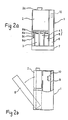
- Coin return control system 1 includes coin distributing mechanism 2 at front upper position thereof and change retaining tubes 3, 4 and 5 for one hundred, ten and fifty unit coins, respectively, disposed in series under coin distributing mechanism 2.
- Auxiliary change retaining tube 6 is disposed adjacent to coin distributing mechanism 2 and change retaining tube 5.
- Coin paying-out mechanism 7 is disposed below change retaining tubes 3, 4 and 5, and auxiliary change retaining tube 6.
- a plurality of switches 8a-8d corresponding to respective change retaining tubes 3, 4 and 5 are disposed adjacent to change retaining tube 3.
- Control unit 9 is disposed behind the above tubes and mechanism.
- Coin type predetermination switch 10 is disposed on control unit 9 at its upper end to enable to be operated by removing auxiliary change retaining tube 6.
- a coin deposited into coin inlet 2a of coin distributing mechanism 2 is determined at its authenticity and type during its passage through coin distributing mechanism 2.
- the coin determined to be an unacceptable coin for example, a metal slug or foreign coin
- a return opening not shown.
- a deposited coin is an acceptable coin, and when it is determined to be a one hundred monetary unit coin, it is distributed to change retaining tube 3; when it is determined to be a ten unit coin, it is distributed to change retaining tube 4; when it is determined to be a fifty unit coin, it is distributed to change retaining tube 5.
- change retaining tubes 3, 4 and 5 are filled with respective corresponding coins, it is distributed to a safe.
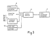
- Coin distributing mechanism 2 distributes the deposited coin in accordance with the instruction from control portion 11 (a micro-computer) disposed on control unit 9.
- control portion 11 is directly connected to several portions, e.g., coin distributing mechanism 2, coin paying-out mechanism 7, inventory switches 8a-8d, coin type predetermination switch 10 and operating portion 12 of a vending machine, respectively.
- Coin distributing mechanism 2 includes a sensor (not shown) to detect the materials, form and the other things of the deposited coin and outputs the detected signal to control portion 11.
- Coin distributing mechanism 2 operates distributing gates (not shown) in accordance with signals from control portion 11, and introduces the deposited coin into the respective corresponding change retaining tubes 3, 4 and 5.
- Coin paying-out mechanism 7 pays out a coin from change retaining tubes 3, 4 or 5 or auxiliary change retaining tube 6 to a return opening (not shown) in accordance with the instruction of control portion 11 and includes a plurality of sensors (not shown) to detect the number of the remaining coins in change retaining tubes 3, 4 and 5. When the number of the remaining coins respective therein is zero, coin paying-out mechanism 7 outputs a signal to communicate a such a condition into control portion 11.
- Inventory switches 8a-8d outputs a signal to forcedly pay out a coin in change retaining tubes 3, 4 or 5 or auxiliary change retaining tube 6 into control portion 11. For example, before a vending machine starts to sale a merchandise, the condition of paying out a coin in change retaining tubes 3, 4 or 5 or auxiliary retaining tube 6 to a return opening can be tested by operating inventory switches 8a-8d.
- Coin type predetermination switch 10 is to predetermine the coin type of the coin in auxiliary change retaining tube 6, which retains the coin often paid out as change.
- the coin type of the coin paid out as change can be changed by operating coin type predetermination switch 10 so that the coin type can be corresponded to the price of the merchandise.
- the predetermined value of coin predetermination switch 10 is detected by control portion 11 every predetermined time.
- step SP10 predetermined value D predetermined by coin type predetermination switch 10 is input to control portion 11. Then, it is determined in step SP11 whether or not inventory switch 8d corresponding to auxiliary change retaining tube 6 is turned on. If it is turned on, the output of step spll is input to step SP12, and predetermined value D is memorized as defined coin type value Df in step SP12. Although not shown in the flow chart, when it is turned on, the output of step SP11 is input to coin paying-out mechanism 7 to pay out a coin from auxiliary change retaining tube 6, and the condition of paying-out a coin is thus tested.
- step SP11 is input to step SP13, and it is determined in step SP13 whether or not predetermined value D equals defined coin type value Df. If predetermined value D does not equal defined coin type value Df, the output of step SP13 is input to step SP14 and the paying-out a coin from auxiliary change retaining tube 6 is prohibited. Otherwise, the output of step SP13 is input to step SP15, and it is determined in step SP15 whether or not it is necessary to pay out a coin. That is, it is determined therein whether or not it is necessary to pay out a coin based on the result of the comparison of the amount of the coin deposited through coin inlet 2a with the selling price of a purchase.
- step SP15 If not necessary, the output of step SP15 is returned to step SP10. Otherwise, the output of step SP15 is input to step SP16. It is determined in step SP16 whether or not the coin of the coin type corresponding to defined coin type value Df, i.e., the coin in auxiliary change retaining tube 6, is necessary. If it is not necessary, the output of step SP16 is input to step SP17, and coin paying-out mechanism 7 is thus instructed so that a necessary coin can be paid out from change retaining tubes 3, 4 or 5 except for a change retaining tube corresponding to the coin type of auxiliary change retaining tube 6.
- step SP16 is input to step SP18, and it is determined in step SP18 whether or not the number of the remaining coin in the change retaining tube corresponding to defined coin type value Df is zero. If it is zero, the output of step SP18 is input to step SP17. Otherwise, the output of step SP18 is input to step SP19, and it is determined in step SP19 whether or not the paying-out a coin from auxiliary change retaining tube 6 is prohibited. If it is not prohibited, the output of step SP19 is input to step SP20, and the number of the necessary coin is paid out from auxiliary change retaining tube 6. Otherwise, the output of step SP19 is returned to step SP 10.
- predetermined value D of coin type predetermination switch 10 is changed in spite of that inventory switch 8d corresponding to auxiliary change retaining tube 6 is not turned on, the paying-out of a coin from auxiliary change retaining tube 6 is prohibited. Accordingly, even though predetermined value D is caused to be varied because of the bad condition in contact of coin type predetermination switch 10 or predetermined value D is caused to be varied because of invading liquid like water into coin type predetermination switch 10, it can be prevented to pay out the coin of a different coin type from auxiliary change retaining tube 6 as change.
Landscapes
- Physics & Mathematics (AREA)
- General Physics & Mathematics (AREA)
- Control Of Vending Devices And Auxiliary Devices For Vending Devices (AREA)
Applications Claiming Priority (2)
| Application Number | Priority Date | Filing Date | Title |
|---|---|---|---|
| JP52612/89U | 1989-05-09 | ||
| JP5261289U JPH02145465U (fr) | 1989-05-09 | 1989-05-09 |
Publications (2)
| Publication Number | Publication Date |
|---|---|
| EP0397353A2 true EP0397353A2 (fr) | 1990-11-14 |
| EP0397353A3 EP0397353A3 (fr) | 1991-01-02 |
Family
ID=12919621
Family Applications (1)
| Application Number | Title | Priority Date | Filing Date |
|---|---|---|---|
| EP19900304507 Withdrawn EP0397353A3 (fr) | 1989-05-09 | 1990-04-26 | Système de surveillance de restitution de monnaie pour machines de vente |
Country Status (2)
| Country | Link |
|---|---|
| EP (1) | EP0397353A3 (fr) |
| JP (1) | JPH02145465U (fr) |
Cited By (5)
| Publication number | Priority date | Publication date | Assignee | Title |
|---|---|---|---|---|
| WO1992002906A1 (fr) * | 1990-08-01 | 1992-02-20 | Mars Incorporated | Mecanisme pour pieces de monnaie |
| FR2688084A1 (fr) * | 1992-02-27 | 1993-09-03 | Coin Acceptors Inc | Dispositif de commande d'une transaction commerciale. |
| EP0569956A3 (en) * | 1992-05-13 | 1994-08-24 | Nippon Conlux Co Ltd | Coin processor |
| EP1050857A3 (fr) * | 1997-06-18 | 2001-01-17 | Mars Incorporated | Machine pour le traitement de la monnaie |
| CN101089899B (zh) * | 2006-06-12 | 2010-09-15 | 旭精工株式会社 | 圆片的分配装置 |
Families Citing this family (1)
| Publication number | Priority date | Publication date | Assignee | Title |
|---|---|---|---|---|
| JP6227453B2 (ja) * | 2014-03-24 | 2017-11-08 | 株式会社日本コンラックス | 硬貨処理装置 |
Family Cites Families (5)
| Publication number | Priority date | Publication date | Assignee | Title |
|---|---|---|---|---|
| US3896915A (en) * | 1973-01-17 | 1975-07-29 | Nippon Coinco Co Ltd | Vending machine |
| JPS6057626B2 (ja) * | 1976-04-30 | 1985-12-16 | 株式会社日本コインコ | 自動販売機の制御装置 |
| JPH0630919B2 (ja) * | 1983-08-18 | 1994-04-27 | 富士通株式会社 | 媒体処理装置 |
| JPS6072093A (ja) * | 1983-09-28 | 1985-04-24 | 株式会社日本コンラックス | 硬貨払出装置 |
| FR2609341B1 (fr) * | 1987-01-06 | 1989-03-03 | Cga Hbs | Distributeur automatique a rendu de monnaie |
-
1989
- 1989-05-09 JP JP5261289U patent/JPH02145465U/ja active Pending
-
1990
- 1990-04-26 EP EP19900304507 patent/EP0397353A3/fr not_active Withdrawn
Cited By (9)
| Publication number | Priority date | Publication date | Assignee | Title |
|---|---|---|---|---|
| WO1992002906A1 (fr) * | 1990-08-01 | 1992-02-20 | Mars Incorporated | Mecanisme pour pieces de monnaie |
| US5356332A (en) * | 1990-08-01 | 1994-10-18 | Mars Incorporated | Coin mechanism |
| FR2688084A1 (fr) * | 1992-02-27 | 1993-09-03 | Coin Acceptors Inc | Dispositif de commande d'une transaction commerciale. |
| EP0569956A3 (en) * | 1992-05-13 | 1994-08-24 | Nippon Conlux Co Ltd | Coin processor |
| US5460568A (en) * | 1992-05-13 | 1995-10-24 | Kabushiki Kaisha Nippon Conlux | Coin processor |
| EP1050857A3 (fr) * | 1997-06-18 | 2001-01-17 | Mars Incorporated | Machine pour le traitement de la monnaie |
| EP1327964A3 (fr) * | 1997-06-18 | 2004-09-29 | Mars Incorporated | Machine pour le traitement de la monnaie |
| CN101089899B (zh) * | 2006-06-12 | 2010-09-15 | 旭精工株式会社 | 圆片的分配装置 |
| TWI395157B (zh) * | 2006-06-12 | 2013-05-01 | Asahi Seiko Co Ltd | The distinguishing device of the dish |
Also Published As
| Publication number | Publication date |
|---|---|
| JPH02145465U (fr) | 1990-12-10 |
| EP0397353A3 (fr) | 1991-01-02 |
Similar Documents
| Publication | Publication Date | Title |
|---|---|---|
| US5409092A (en) | Vending system capable of renewing record of a prepaid card | |
| US4491140A (en) | Coin handling apparatus | |
| US4376479A (en) | Total sales indication device for a vending machine | |
| US4499985A (en) | Vendor change return control | |
| KR940008126B1 (ko) | 자동판매기의 제어장치 | |
| EP0397353A2 (fr) | Système de surveillance de restitution de monnaie pour machines de vente | |
| US4836309A (en) | Electronic weighing instrument | |
| US5181882A (en) | Coin return control system for vending machines | |
| CA2170471C (fr) | Methode de paiement global et appareil de commande | |
| US5595277A (en) | Coin payout method and control means | |
| EP0993661B1 (fr) | Procede de fonctionnement d'un mecanisme de pieces de monnaie | |
| US5577957A (en) | Coin payout method and control apparatus | |
| EP0167181B2 (fr) | Dispositif pour le traitement de pièces de monnaie | |
| KR960001453B1 (ko) | 자동판매기 | |
| EP0484824A2 (fr) | Mécanisme de traitement de pièces de monnaie pour machines de vente | |
| JPS6210863Y2 (fr) | ||
| JP2967652B2 (ja) | 自動販売機の売り切れ検出装置 | |
| JP2868054B2 (ja) | 自動販売機の釣銭払出制御装置 | |
| JPS6136279B2 (fr) | ||
| KR100269783B1 (ko) | 자동 판매기의 현금 입출력 방법 | |
| JP3015439B2 (ja) | 自動販売機の商品送出装置 | |
| JPS633358B2 (fr) | ||
| RU2126172C1 (ru) | Устройство контроля емкости хранения монет для автоматического торгового аппарата | |
| JPS6144357B2 (fr) | ||
| JPS6135596B2 (fr) |
Legal Events
| Date | Code | Title | Description |
|---|---|---|---|
| PUAI | Public reference made under article 153(3) epc to a published international application that has entered the european phase |
Free format text: ORIGINAL CODE: 0009012 |
|
| PUAL | Search report despatched |
Free format text: ORIGINAL CODE: 0009013 |
|
| AK | Designated contracting states |
Kind code of ref document: A2 Designated state(s): DE ES FR GB IT |
|
| AK | Designated contracting states |
Kind code of ref document: A3 Designated state(s): DE ES FR GB IT |
|
| 17P | Request for examination filed |
Effective date: 19901224 |
|
| STAA | Information on the status of an ep patent application or granted ep patent |
Free format text: STATUS: THE APPLICATION HAS BEEN WITHDRAWN |
|
| 18W | Application withdrawn |
Withdrawal date: 19930211 |