EP0397381A2 - Anzeigeeinheit vom Projektionstyp unter Verwendung von Flüssigkristall-Anzeigevorrichtungen - Google Patents
Anzeigeeinheit vom Projektionstyp unter Verwendung von Flüssigkristall-Anzeigevorrichtungen Download PDFInfo
- Publication number
- EP0397381A2 EP0397381A2 EP90304768A EP90304768A EP0397381A2 EP 0397381 A2 EP0397381 A2 EP 0397381A2 EP 90304768 A EP90304768 A EP 90304768A EP 90304768 A EP90304768 A EP 90304768A EP 0397381 A2 EP0397381 A2 EP 0397381A2
- Authority
- EP
- European Patent Office
- Prior art keywords
- projection type
- display unit
- type display
- crystal display
- light
- Prior art date
- Legal status (The legal status is an assumption and is not a legal conclusion. Google has not performed a legal analysis and makes no representation as to the accuracy of the status listed.)
- Withdrawn
Links
Images


Classifications
-
- G—PHYSICS
- G09—EDUCATION; CRYPTOGRAPHY; DISPLAY; ADVERTISING; SEALS
- G09F—DISPLAYING; ADVERTISING; SIGNS; LABELS OR NAME-PLATES; SEALS
- G09F9/00—Indicating arrangements for variable information in which the information is built-up on a support by selection or combination of individual elements
- G09F9/30—Indicating arrangements for variable information in which the information is built-up on a support by selection or combination of individual elements in which the desired character or characters are formed by combining individual elements
- G09F9/35—Indicating arrangements for variable information in which the information is built-up on a support by selection or combination of individual elements in which the desired character or characters are formed by combining individual elements being liquid crystals
-
- H—ELECTRICITY
- H04—ELECTRIC COMMUNICATION TECHNIQUE
- H04N—PICTORIAL COMMUNICATION, e.g. TELEVISION
- H04N9/00—Details of colour television systems
- H04N9/12—Picture reproducers
- H04N9/31—Projection devices for colour picture display, e.g. using electronic spatial light modulators [ESLM]
- H04N9/3102—Projection devices for colour picture display, e.g. using electronic spatial light modulators [ESLM] using two-dimensional electronic spatial light modulators
- H04N9/3105—Projection devices for colour picture display, e.g. using electronic spatial light modulators [ESLM] using two-dimensional electronic spatial light modulators for displaying all colours simultaneously, e.g. by using two or more electronic spatial light modulators
-
- H—ELECTRICITY
- H04—ELECTRIC COMMUNICATION TECHNIQUE
- H04N—PICTORIAL COMMUNICATION, e.g. TELEVISION
- H04N9/00—Details of colour television systems
- H04N9/12—Picture reproducers
- H04N9/31—Projection devices for colour picture display, e.g. using electronic spatial light modulators [ESLM]
- H04N9/3179—Video signal processing therefor
- H04N9/3182—Colour adjustment, e.g. white balance, shading or gamut
Definitions
- the present invention relates to a projection type display unit which obtains a picture image by combining and projecting optical images formed in a plurality of liquid crystal display devices.
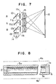
- FIG. 7 One example of a conventional projection type display unit, in which three liquid crystal display devices (LCD) 11r, 11g and 11b are used, is shown in Fig. 7. Picture images corresponding to three primary colors R, G and B are formed on these three devices (LCD) 11r, 11g, and 11b, respectively. After a white light from a light source 14 is made to pass through an infrared-ray cutting filter 13, it is divided into the three primary colors R, G and B by using dichroic mirrors 12r, 12g and 12b. Picture-image light obtained by introducing these three primary colors into each corresponding LCD is projected and combined on a screen 16 by means of projection lenses 15r, 15g and 15b.
- LCD liquid crystal display devices
- the luminance ratio of R, G and B In order to reproduce (referred to as "achieving white balance") a white or gray color on a screen, which humans feel most natural in the sense of sight, the luminance ratio of R, G and B must be set to a certain value. For example, by setting the luminance ratio of the three primary colors R (wavelength: 610 nm), G (wavelength: 545 nm) and B (wavelength: 450 nm) to about 3: 6: 1, a white or gray color without coloring can be reproduced. However, this ratio varies as a result of changes in wavelength and spectroscopic characteristics of three primary color lights.
- the illumination ratio of R, G and B lights entered into the three LCDs usually differs from the above-described value.
- a white balance cannot be achieved on a screen.
- a signal voltage which is applied to an LCD is made to vary among LCDs corresponding to R, G and B and a white balance is achieved by varying its transmittance.
- Fig. 8 shows the cross section of an LCD in which a twisted-nematic (TN) mode liquid crystal is used.
- a liquid crystal is sandwiched between two transparent boards 1a and 1b, the inner surfaces of which are opposed to each other and orientation processing has been performed.
- Polarizing plates 4a and 4b are disposed in the interfaces between the outside atmosphere and two transparent boards so that polarizing axises are in parallel to each other.
- a transparent electrode is disposed on the side in contact with the liquid crystals of the two transparent boards. By applying a signal voltage between these two transparent electrodes 3a and 3b, transmittance can be varied.
- Fig. 9 shows the transmittance-signal voltage characteristics of an LCD.
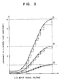
- Fig. 4 shows the luminance - signal voltage characteristics for R (wavelength: 610 nm), G (wavelength: 545 nm) and B (wavelength: 450 nm) on a screen measured by driving LCDs for R, G, B, which are incorporated in a projection type display unit of Fig. 8, independently from each other. Since the luminance ratio of the R, G and B is not 3: 6: 1 under the same signal voltage, a white balance cannot be achieved by driving an LCD under the same condition. Therefore, as shown in Fig. 4, by lowering the maximum applied signal voltage (Vr, Vg, Vd) successively in the order of G, R and B, the maximum luminance ratio of R, G and B on a screen is set to 3: 6: 1.
- the input voltage in the horizontal axis corresponds to the primary color signal voltage of each R, G and B while the output voltage in the vertical axis corresponds to LCD input signal voltage of each R, G and B.
- Such correction as to enlarge the low voltage section or the high voltage section of the primary color signal voltage is applied.
- the characteristics of correction circuits differ for the primary color signals for R, G and B.
- B such a correction as to enlarge the low voltage section or the high voltage section of the primary color signal voltage is applied, whereas as regards R and G, only the low voltage section is enlarged.
- the amplification factor also differs for R, G and B. That is, correction circuits having different characteristics must be provided on the LCDs corresponding to the R, G and B.
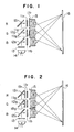
- a means for varying the luminance ratio of R, G and B is provided in the light path between a light source and a screen so that the displayed picture image, which is emitted through three liquid crystal display devices in a state in which transmittance has reached a maximum saturation state or transmittances of them are almost equal and which are combined on a screen, becomes a well-color-balanced white color.
- Fig. 1 shows a projection type display unit of the present invention in which three liquid crystal display devices (LCD) 11r, 11g and 11b are used. Picture images corresponding to three primary colors R, G and B are formed through these three devices (LCD) 11r, 11g, and 11b, respectively. After a white light from a light source 14 is made to pass through an infrared-ray cutting filter 13, it is divided into the three primary colors R (wavelength: 610 nm), G (wavelength: 545 nm) and B (wavelength: 450 nm) by using dichroic mirrors 12r, 12g and 12b.
- LCD liquid crystal display devices
- Picture-image light obtained by introducing the these three primary colors into respective corresponding LCDs is projected and combined on a screen 16 by means of projection lenses 15r, 15g and 15b. Further, neutral density filters 17r and 17g of transmittances 54% and 86% respectively are disposed on the emission side of LCDs corresponding to R and G.
- Fig. 4 shows the luminance-signal voltage characteristics on a screen when the neutral density filters 17r and 17g are not disposed.
- FIG. 3 shows the luminance-signal voltage characteristics on a screen when the neutral density filters 17r and 17g are disposed and white balance is achieved.
- Fig. 11 shows input and output characteristics of a correction circuit for primary color signals of R, G and B in the present invention.
- the input voltage in the horizontal axis corresponds to the primary color signal voltage of each R, G and B while the output voltage in the vertical axis corresponds to LCD input signal voltage of each R, G and B.
- the same correction is made for R, G and B. Therefore, since a correction circuit having the same characteristics can be used, the present invention has an advantage that the structure of a driving circuit is simplified.
- Fig. 2 shows a projection type display unit of the present invention in which three liquid crystal display devices (LCD) 11r, 11g and 11b are used.
- LCD liquid crystal display devices
- the basic construction thereof is the same as that of the first embodiment.
- neutral density filters 18r and 18g having transmittances 54%, 86% respectively are disposed on the incidence side of LCDs for R and G instead of the emission side of the LCDs.
- interference filters 18r and 18g in place of neutral density filters are disposed on the light incidence side of LCDs for R and G.
- the three primary colors that enter an LCD have a distribution with a certain wavelength as a peak.
- the peak transmission light quantity and the spectroscopic characteristics of R, G and B are made to vary and a white balance is achieved.
- the dashed line indicates wavelength characteristics after the light is divided by a dichroic mirror; the solid line indicates wavelength characteristics after the light is further made to pass through the interference filters 18r and 18g and a white balance is achieved.
- this embodiment has the same advantage as that of the second embodiment.
- This embodiment has the additional advantage that, since the wavelength distribution range of R and G lights is narrower than that of the prior art, the color purity of the picture image on a screen is improved and the picture quality is improved.
- the same advantage as that of the above-mentioned embodiment can be expected if absorption type filters such as color glass filters, or gelatin filters are used in place of the interference filters.
- absorption type filters such as color glass filters, or gelatin filters are used in place of the interference filters.
- the same advantage as that of the above-mentioned embodiment can be expected by changing the reflection characteristics of the dichroic mirrors 12r and 12g according to R, G and B even if a filter is not newly disposed.
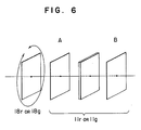
- FIG. 6 is a schematic configurational view in which sections of this polarizing plate and LCDs are enlarged.
- This polarizing plate is made rotatable by a signal from the outside about the incidence axis in a plane vertical to the light incidence direction so that the direction of the polarizing axis can be changed at will.
- the intersection angle of another polarizing plate A with respect to the polarizing axis the illuminance of light that enters into an LCD is made controllable.
- the illuminance of the incidence to LCDs for R, G and B is controlled and a white balance is achieved on a screen.
- this embodiment has the same advantage as that of the second embodiment.
- the first through the third embodiments have a problem in that, even under a state in which a white balance is achieved at a start time, variations in the transmittance of an LCD as the result of variations in the temperature of this unit and variations in the spectroscopic characteristics as the result of the degradation of the light source occur and a white balance cannot be achieved.
- This embodiment also has the advantage that, by varying the direction of the polarizing axes of the polarizing plates 18r and 18g by supplying a signal from the outside, the light quantity incident on an LCD is made to vary and a return to the state in which a white balance is kept is made possible.
Landscapes
- Engineering & Computer Science (AREA)
- Multimedia (AREA)
- Signal Processing (AREA)
- Chemical & Material Sciences (AREA)
- Crystallography & Structural Chemistry (AREA)
- Physics & Mathematics (AREA)
- General Physics & Mathematics (AREA)
- Theoretical Computer Science (AREA)
- Projection Apparatus (AREA)
- Liquid Crystal (AREA)
- Devices For Indicating Variable Information By Combining Individual Elements (AREA)
- Video Image Reproduction Devices For Color Tv Systems (AREA)
Applications Claiming Priority (2)
| Application Number | Priority Date | Filing Date | Title |
|---|---|---|---|
| JP1114728A JPH02293732A (ja) | 1989-05-08 | 1989-05-08 | 投写型表示装置 |
| JP114728/89 | 1989-05-08 |
Publications (2)
| Publication Number | Publication Date |
|---|---|
| EP0397381A2 true EP0397381A2 (de) | 1990-11-14 |
| EP0397381A3 EP0397381A3 (de) | 1990-12-27 |
Family
ID=14645142
Family Applications (1)
| Application Number | Title | Priority Date | Filing Date |
|---|---|---|---|
| EP19900304768 Withdrawn EP0397381A3 (de) | 1989-05-08 | 1990-05-02 | Anzeigeeinheit vom Projektionstyp unter Verwendung von Flüssigkristall-Anzeigevorrichtungen |
Country Status (3)
| Country | Link |
|---|---|
| EP (1) | EP0397381A3 (de) |
| JP (1) | JPH02293732A (de) |
| KR (1) | KR930005431B1 (de) |
Cited By (4)
| Publication number | Priority date | Publication date | Assignee | Title |
|---|---|---|---|---|
| EP0477028A3 (en) * | 1990-09-21 | 1992-09-02 | Matsushita Electric Industrial Co., Ltd | Image projection system |
| WO2002079856A3 (en) * | 2001-03-30 | 2003-04-10 | Koninkl Philips Electronics Nv | Projection display system with white balance control |
| EP0568998B1 (de) * | 1992-05-06 | 2003-04-16 | Canon Kabushiki Kaisha | Vorrichtung zur Erzeugung von Bildern und ein diese verwendender Projektor |
| EP1530378A3 (de) * | 2003-11-10 | 2007-01-24 | Seiko Epson Corporation | Projektor |
Family Cites Families (5)
| Publication number | Priority date | Publication date | Assignee | Title |
|---|---|---|---|---|
| JPS62295025A (ja) * | 1986-06-16 | 1987-12-22 | Seiko Epson Corp | 投射型表示装置 |
| JPS63216026A (ja) * | 1987-03-05 | 1988-09-08 | Ricoh Co Ltd | 投写型液晶表示装置 |
| JPS63284592A (ja) * | 1987-05-15 | 1988-11-21 | 株式会社リコー | 投写型液晶表示装置 |
| JPS6432289A (en) * | 1987-07-28 | 1989-02-02 | Seiko Epson Corp | Projection type color display device |
| US4989954A (en) * | 1987-10-09 | 1991-02-05 | Matsushita Electric Industrial Co., Ltd. | Projection type liquid cyrstal display device |
-
1989
- 1989-05-08 JP JP1114728A patent/JPH02293732A/ja active Pending
-
1990
- 1990-05-02 EP EP19900304768 patent/EP0397381A3/de not_active Withdrawn
- 1990-05-08 KR KR1019900006467A patent/KR930005431B1/ko not_active Expired - Fee Related
Cited By (6)
| Publication number | Priority date | Publication date | Assignee | Title |
|---|---|---|---|---|
| EP0477028A3 (en) * | 1990-09-21 | 1992-09-02 | Matsushita Electric Industrial Co., Ltd | Image projection system |
| EP0568998B1 (de) * | 1992-05-06 | 2003-04-16 | Canon Kabushiki Kaisha | Vorrichtung zur Erzeugung von Bildern und ein diese verwendender Projektor |
| EP1148736A3 (de) * | 1992-05-06 | 2007-06-13 | Canon Kabushiki Kaisha | Vorrichtung zur Erzeugung von Bildern und ein diese verwendender Projektor |
| WO2002079856A3 (en) * | 2001-03-30 | 2003-04-10 | Koninkl Philips Electronics Nv | Projection display system with white balance control |
| US6674579B2 (en) | 2001-03-30 | 2004-01-06 | Koninklijke Philips Electronics N.V. | Color correction to target white points by adjustment of two colors |
| EP1530378A3 (de) * | 2003-11-10 | 2007-01-24 | Seiko Epson Corporation | Projektor |
Also Published As
| Publication number | Publication date |
|---|---|
| JPH02293732A (ja) | 1990-12-04 |
| KR900018894A (ko) | 1990-12-22 |
| KR930005431B1 (ko) | 1993-06-21 |
| EP0397381A3 (de) | 1990-12-27 |
Similar Documents
| Publication | Publication Date | Title |
|---|---|---|
| US6870523B1 (en) | Device, system and method for electronic true color display | |
| US20060285217A1 (en) | Multi-primary color display | |
| CN101354874B (zh) | 显示设备 | |
| US6052166A (en) | LCD projector comprising light sensor and correction circuit | |
| US5184238A (en) | Apparatus for projecting light onto a surface having reflector means for improving the brightness of the image | |
| JPH0784280A (ja) | カラー画像表示装置 | |
| GB2191057A (en) | Colour video display arrangement | |
| US5779334A (en) | Enhanced video projection system | |
| US5826961A (en) | Rear projector employing an image display | |
| EP0397381A2 (de) | Anzeigeeinheit vom Projektionstyp unter Verwendung von Flüssigkristall-Anzeigevorrichtungen | |
| US5488436A (en) | Liquid crystal projector | |
| US20040263942A1 (en) | Display system allowing enhanced dynamic range | |
| JP2000347137A (ja) | プロジェクター装置 | |
| JP2004361500A (ja) | 照明装置、投射型表示装置及びその駆動方法 | |
| JPS62295025A (ja) | 投射型表示装置 | |
| JPH03249639A (ja) | 液晶プロジェクタ | |
| JP2795618B2 (ja) | 投射型表示装置 | |
| JP2656854B2 (ja) | 液晶投映装置 | |
| JP2001005124A (ja) | 画像表示装置 | |
| JPH0534846A (ja) | 投写型カラー画像表示装置 | |
| KR200256910Y1 (ko) | 액정프로젝터의화이트밸런스장치 | |
| JP2842419B2 (ja) | 投射型表示装置 | |
| JPH0383045A (ja) | 投射型表示装置 | |
| JPH0777689A (ja) | 液晶投写装置 | |
| JPH06347747A (ja) | 液晶プロジェクター |
Legal Events
| Date | Code | Title | Description |
|---|---|---|---|
| PUAI | Public reference made under article 153(3) epc to a published international application that has entered the european phase |
Free format text: ORIGINAL CODE: 0009012 |
|
| PUAL | Search report despatched |
Free format text: ORIGINAL CODE: 0009013 |
|
| AK | Designated contracting states |
Kind code of ref document: A2 Designated state(s): DE FR GB |
|
| AK | Designated contracting states |
Kind code of ref document: A3 Designated state(s): DE FR GB |
|
| 17P | Request for examination filed |
Effective date: 19901228 |
|
| 17Q | First examination report despatched |
Effective date: 19930506 |
|
| STAA | Information on the status of an ep patent application or granted ep patent |
Free format text: STATUS: THE APPLICATION IS DEEMED TO BE WITHDRAWN |
|
| 18D | Application deemed to be withdrawn |
Effective date: 19940205 |