EP0397603B1 - Fixation de sécurité de ski avec réglage automatique de la force de déclenchement - Google Patents
Fixation de sécurité de ski avec réglage automatique de la force de déclenchement Download PDFInfo
- Publication number
- EP0397603B1 EP0397603B1 EP90810352A EP90810352A EP0397603B1 EP 0397603 B1 EP0397603 B1 EP 0397603B1 EP 90810352 A EP90810352 A EP 90810352A EP 90810352 A EP90810352 A EP 90810352A EP 0397603 B1 EP0397603 B1 EP 0397603B1
- Authority
- EP
- European Patent Office
- Prior art keywords
- ski
- safety binding
- attachment
- binding according
- control device
- Prior art date
- Legal status (The legal status is an assumption and is not a legal conclusion. Google has not performed a legal analysis and makes no representation as to the accuracy of the status listed.)
- Expired - Lifetime
Links
Images




Classifications
-
- A—HUMAN NECESSITIES
- A63—SPORTS; GAMES; AMUSEMENTS
- A63C—SKATES; SKIS; ROLLER SKATES; DESIGN OR LAYOUT OF COURTS, RINKS OR THE LIKE
- A63C9/00—Ski bindings
- A63C9/08—Ski bindings yieldable or self-releasing in the event of an accident, i.e. safety bindings
- A63C9/088—Ski bindings yieldable or self-releasing in the event of an accident, i.e. safety bindings with electronically controlled locking devices
-
- A—HUMAN NECESSITIES
- A63—SPORTS; GAMES; AMUSEMENTS
- A63C—SKATES; SKIS; ROLLER SKATES; DESIGN OR LAYOUT OF COURTS, RINKS OR THE LIKE
- A63C9/00—Ski bindings
- A63C9/08—Ski bindings yieldable or self-releasing in the event of an accident, i.e. safety bindings
- A63C9/081—Ski bindings yieldable or self-releasing in the event of an accident, i.e. safety bindings with swivel sole-plate
-
- A—HUMAN NECESSITIES
- A63—SPORTS; GAMES; AMUSEMENTS
- A63C—SKATES; SKIS; ROLLER SKATES; DESIGN OR LAYOUT OF COURTS, RINKS OR THE LIKE
- A63C9/00—Ski bindings
- A63C9/08—Ski bindings yieldable or self-releasing in the event of an accident, i.e. safety bindings
- A63C9/084—Ski bindings yieldable or self-releasing in the event of an accident, i.e. safety bindings with heel hold-downs, e.g. swingable
- A63C9/0841—Ski bindings yieldable or self-releasing in the event of an accident, i.e. safety bindings with heel hold-downs, e.g. swingable with a single jaw
- A63C9/0842—Ski bindings yieldable or self-releasing in the event of an accident, i.e. safety bindings with heel hold-downs, e.g. swingable with a single jaw the jaw pivoting on the body or base about a transverse axis
-
- A—HUMAN NECESSITIES
- A63—SPORTS; GAMES; AMUSEMENTS
- A63C—SKATES; SKIS; ROLLER SKATES; DESIGN OR LAYOUT OF COURTS, RINKS OR THE LIKE
- A63C9/00—Ski bindings
- A63C9/08—Ski bindings yieldable or self-releasing in the event of an accident, i.e. safety bindings
- A63C9/084—Ski bindings yieldable or self-releasing in the event of an accident, i.e. safety bindings with heel hold-downs, e.g. swingable
- A63C9/0845—Ski bindings yieldable or self-releasing in the event of an accident, i.e. safety bindings with heel hold-downs, e.g. swingable the body or base or a jaw pivoting about a vertical axis, i.e. side release
-
- A—HUMAN NECESSITIES
- A63—SPORTS; GAMES; AMUSEMENTS
- A63C—SKATES; SKIS; ROLLER SKATES; DESIGN OR LAYOUT OF COURTS, RINKS OR THE LIKE
- A63C9/00—Ski bindings
- A63C9/08—Ski bindings yieldable or self-releasing in the event of an accident, i.e. safety bindings
- A63C9/084—Ski bindings yieldable or self-releasing in the event of an accident, i.e. safety bindings with heel hold-downs, e.g. swingable
- A63C9/0846—Details of the release or step-in mechanism
-
- A—HUMAN NECESSITIES
- A63—SPORTS; GAMES; AMUSEMENTS
- A63C—SKATES; SKIS; ROLLER SKATES; DESIGN OR LAYOUT OF COURTS, RINKS OR THE LIKE
- A63C9/00—Ski bindings
- A63C9/08—Ski bindings yieldable or self-releasing in the event of an accident, i.e. safety bindings
- A63C9/085—Ski bindings yieldable or self-releasing in the event of an accident, i.e. safety bindings with sole hold-downs, e.g. swingable
- A63C9/08535—Ski bindings yieldable or self-releasing in the event of an accident, i.e. safety bindings with sole hold-downs, e.g. swingable with a mobile body or base or single jaw
- A63C9/08542—Ski bindings yieldable or self-releasing in the event of an accident, i.e. safety bindings with sole hold-downs, e.g. swingable with a mobile body or base or single jaw pivoting about a transversal axis
-
- A—HUMAN NECESSITIES
- A63—SPORTS; GAMES; AMUSEMENTS
- A63C—SKATES; SKIS; ROLLER SKATES; DESIGN OR LAYOUT OF COURTS, RINKS OR THE LIKE
- A63C9/00—Ski bindings
- A63C9/08—Ski bindings yieldable or self-releasing in the event of an accident, i.e. safety bindings
- A63C9/085—Ski bindings yieldable or self-releasing in the event of an accident, i.e. safety bindings with sole hold-downs, e.g. swingable
- A63C9/08535—Ski bindings yieldable or self-releasing in the event of an accident, i.e. safety bindings with sole hold-downs, e.g. swingable with a mobile body or base or single jaw
- A63C9/0855—Ski bindings yieldable or self-releasing in the event of an accident, i.e. safety bindings with sole hold-downs, e.g. swingable with a mobile body or base or single jaw pivoting about a vertical axis
-
- A—HUMAN NECESSITIES
- A63—SPORTS; GAMES; AMUSEMENTS
- A63C—SKATES; SKIS; ROLLER SKATES; DESIGN OR LAYOUT OF COURTS, RINKS OR THE LIKE
- A63C9/00—Ski bindings
- A63C9/08—Ski bindings yieldable or self-releasing in the event of an accident, i.e. safety bindings
- A63C9/085—Ski bindings yieldable or self-releasing in the event of an accident, i.e. safety bindings with sole hold-downs, e.g. swingable
- A63C9/08557—Details of the release mechanism
Definitions
- the present invention relates to a safety ski binding with automatic triggering force control, which is able to distinguish between pure torsion and lateral force torsion and to control the opening characteristics accordingly.
- CH-A-659 776 describes a binding which has jaws which can be pivoted about axes and which are connected to a movable transmission plate. This transfer plate is mounted on a ski-fixed pin.
- the advantage of this binding is the simultaneous release of the ski boot at the rear and front end.
- a major disadvantage of this binding is that the resulting transverse forces are absorbed by the ski-fixed pin without their size being able to be determined, a distinction between torsion and transverse force torsion not being possible.
- the patent DE 2324078 does not distinguish the point at which the interference force acts and therefore has the disadvantage that it cannot distinguish pure torsion from transverse force torsion.
- the patent US-4,192,527 has the task of increasing the resistance to lateral forces and reducing the resistance to a pure moment.
- This patent neglects the fact that pure torsion practically does not occur as an external load and also has the disadvantage that even small lateral forces at a sufficiently large distance can lead to large torsional moments, for which there is a large resistance with regard to the lateral force and with regard to the torsional moment little resistance provides what clearly represents a contradiction.
- the patents FR-2.228.507 and CH-16404-73 go even further and pursue the task that the ski binding remains as possible with lateral forces and only opens with pairs of forces or torsional forces. These bindings have the disadvantage that they only know lateral forces and pure torsion and do not take into account the case of transverse force torsion, namely a lateral force acting at a certain distance and thus the torsion which arises in the area of the shoe.
- a skier can only generate torques (M z ) in the xy plane (FIG. 1) (FIG. 2).
- the skier can use the ski pole to generate lateral forces (y direction), but their magnitude can be neglected for the present consideration.
- the loads caused by a fall are forces that act on the skier from the ski via binding, after which pure torques (torsion) can practically not occur. Rather, fall loads are mostly individual forces that attack somewhere on the ski. If these forces act sufficiently far away from the ski boot in the y direction, they also generate torsion, but always in combination with a transverse force (Fig. 3).
- the object of the present invention is to provide a ski binding which is able to distinguish between pure torsional stress around the z-axis (active driving load) and transverse force torsion along the y-axis or around the z-axis (passive fall load).
- Another task is that the triggering moment (-M y ) of the ski binding is additionally controlled in accordance with the simultaneous presence of a longitudinal force (P x ).
- the solution to this problem is characterized according to the invention in that the front and rear jaws of the ski binding are connected to one another by a control element, such that the control element can determine at any time whether a specific load case represents pure torsion or transverse force torsion and can control the triggering force accordingly.
- the invention accordingly relates to the ski binding defined in claim 1.
- 1 shows the definition of the ski-fixed (1) orthogonal coordinate system in which the positive x-axis points forward in the ski direction, the positive y-axis to the side and the positive z-axis upwards.
- FIG. 3a shows the typical reaction at the location of the safety ski binding when an individual force (Q) acts on the ski tip, for example laterally (y direction).
- Fig. 3b said reaction, consisting of a torsional moment M z and a shear force Q, into the reaction forces acting on the front (P v ) and rear (P h ) jaws divided up.
- FIG. 2 shows that in the case of the external torsional moment (FIG. 2) the reactions P v and P h are of the same size and that in the case of the external transverse force (FIG. 3b) the reactions P v and P h are of different sizes.
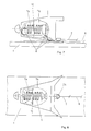
- Fig. 4 shows a front safety jaw (2) with the pivot point (2a) and a cam (2b) for taking the control member (5).
- this lateral displacement (e) is used to shift (s) a transmission member (6), so that, according to FIG. 7, the pretension in the front spring (7a) increases and decreases in the rear spring (7b) becomes.
- the transmission element (6) is deflected with the aid of rollers (8).
- the transmission member (6) is divided into a point (9) and guided twice (Fig. 8).
- FIG. 9a and 9b show how a moment -M y can be generated by the skier, for example with a reserve, without the simultaneous presence of a longitudinal force (active driving load) at which the binding should not open (Avoidance of early opening). With increasing slope inclination, longitudinal force components also occur, but their size is negligible and therefore not shown here.
- 11a and 11b show the ski boot in the ski binding without an external load.
- the springs (15, 16) are biased and mutually balanced. If a longitudinal force now acts on the ski from behind (P x ), the ski boot (12) moves ( ⁇ ) backwards (-x), whereby the spring (16) of the rear jaw (14) loads and the spring (15) the front jaw (13) is relieved, which triggers the moment for a moment -M y earlier, ie the triggering force is reduced.
- Fig. 12 shows the front jaw in the open state after triggering due to a moment -M y .
- a simultaneous deflection of the front and rear jaws has the advantage that the total angle of rotation between the ski boot and the ski is increased, which can increase the time between the occurrence of the load until the trigger limit is reached, which is of great advantage with regard to the reflex times (proprioceptivity) of the skier.
- the special embodiment defined in claim 5 also has the effect that the lower extremity of the skier is also protected in the event of a forward fall. If the skier picks up with his ski tip, the resulting longitudinal force from the front (-P x ) reduces the triggering moment (M y ) on the rear cheek and thus makes it easier for the skier to be released towards the front.
- Holding the ski boot (12) with a spring element (15, 16) attached to the rear and front of the sole (12a) also has the advantage of only slightly influencing the elasticity of the ski in the event of strong deflection.
- the wings (13a, 14a) of the front and rear jaws (13, 14) can also be mounted on the piston (15a, 16a) and thereby moved will.
- the partial task can also be solved with a rear jaw of known type, if this is pushed from the front (-P x ) to the rear (-x) with a force acting on it.
- the displaceability of the ski shoe sole (12a) can be controlled in such a way that different contact points of the ski shoe sole on the toe cheeks exist with and without longitudinal forces (FIG. 13).
- the task can also be solved electronically.
- Electronic bonds generally have force transducers on the front and rear jaws in the directions of interest, so that it can be assumed that the forces P v and P h , P x and -P x as well as the moments M y and -M y are corresponding Sensors are available.
- the processor responsible for triggering the general task (Figs. 2 and 3) is programmed as follows:
- the reduction factor K can be determined as follows: If P v > P h is K ⁇ P v / P h and if Pv ⁇ P h is K ⁇ P h / P v .
Landscapes
- Footwear And Its Accessory, Manufacturing Method And Apparatuses (AREA)
Claims (10)
- Fixation de sécurité de ski comprenant deux dispositifs de retenu (2,3) pivotants autour au moins une axe (z) perpendiculaire à la surface du ski, pour assurer le déclenchement d'une chaussure de ski ou d'une plaque portant la chaussure, d'où les deux dispositifs de retenus sont reliés par un premier organe de commande (5) pour détecter le décalage latéral, caractérisée en ce qu'un membre de transmission (6) est situé entre au moins un des dispositifs de retenu et l'organe de commande (5), de façon à commander la force de déclenchement du dispositif de retenu en fonction de la translation latérale (e) entre le centre (4) de l'organe de commande (5) et l'axe de ski, résultante des décalages latéraux (δ) des dispositifs de retenu par rapport à l'axe de ski.
- Fixation de sécurité de ski selon la revendication 1, caractérisée en ce que le premier organe de commande (5) est réalisé par un organe de commande mécanique, soit une tringle ou une plaque.
- Fixation de sécurité de ski selon la revendication 1, caractérisée en ce que le membre de transmission (6) est réalisé par un membre de transmission mécanique, soit un câble ou une tringle.
- Fixation de sécurité de ski selon une des revendications 1 à 3, caractérisée en ce que le membre de transmission (6) est relié avec le système de déclenchement du dispositif de retenu avant et/ou arrière, de manière à réduire la force de déclenchement de la chaussure lors de la présence d'une torsion à force transversale.
- Fixation de sécurité de ski selon une des revendications 1 à 4, caractérisée en ce que les dispositifs de retenu (13,14) sont pivotants autour au moins une axe supplémentaire (y) dans le plan du ski et perpendiculaire à l'axe longitudinale du ski, d'où un ressort (15,16) est situé dans le dispositif de retenu avant et arrière, destiné à retenir la chaussure de ski (2) à l'avant et à l'arrière par une élasticité identique dans l'axe longitudinale de ski (x), d'où les ressorts sont reliés par un deuxième organe de commande de manière à ce que les élasticités exercées à l'avant et l'arrière de la chaussure deviennent inégaux lors de l'apparition d'une force longitudinale (Px) dans l'axe du ski, pour commander, en fonction de la différence des élasticités, la force de déclenchement du dispositif de retenu avant et/ou arrière sous forme d'un moment de déclenchement (My) exercé sur la chaussure de ski autour d'une axe (y) dans le plan du ski et perpendiculaire à l'axe longitudinale du ski.
- Fixation de sécurité de ski selon une des revendications 1 à 5, caractérisée en ce que la fixation se trouve entièrement à l'intérieur de la projection sur plan horizontal de la semelle de chaussure.
- Fixation de sécurité de ski selon une des revendications 1 à 5, caractérisée en ce que la fixation se trouve entièrement à l'extérieur de la projection sur plan horizontal de la semelle de chaussure.
- Fixation de sécurité de ski selon une des revendications 5 à 7, caractérisée en ce que le deuxième organe de commande entraîne une diminution du moment de déclenchement (-My) du dispositif de retenu avant, lors de la présence d'une force longitudinale exercée sur le ski en direction du ski vers l'avant (Px).
- Fixation de sécurité de ski selon une des revendications 1 à 8, caractérisée en ce qu'elle possède au moins un capteur pour l'acquisition des forces latéraux ou décalages latéraux et/ou forces longitudinaux et au moins un vérin pour la commande du déclenchement, d'où des moyens électroniques de transmission sont présents pour assurer la transmission des signaux entre les capteurs et leurs vérins en leur qualité d'organes de commande et/ou membres de transmission.
- Fixation de sécurité de ski selon une des revendications 5, caractérisée en ce que le deuxième organe de commande se trouve sous forme d'une plaque prévue à porter la chaussure de ski, ou sous forme de la semelle de la chaussure de ski fixée dans la dite fixation de sécurité de ski.
Priority Applications (1)
| Application Number | Priority Date | Filing Date | Title |
|---|---|---|---|
| AT90810352T ATE90585T1 (de) | 1989-05-12 | 1990-05-11 | Sicherheitsskibindung mit automatischer ausloesekraftsteuerung. |
Applications Claiming Priority (4)
| Application Number | Priority Date | Filing Date | Title |
|---|---|---|---|
| CH1783/89A CH679213A5 (en) | 1989-05-12 | 1989-05-12 | Safety release binding for skis |
| CH1784/89 | 1989-05-12 | ||
| CH1783/89 | 1989-05-12 | ||
| CH1784/89A CH679744A5 (en) | 1989-05-12 | 1989-05-12 | Safety release binding for skis |
Publications (2)
| Publication Number | Publication Date |
|---|---|
| EP0397603A1 EP0397603A1 (fr) | 1990-11-14 |
| EP0397603B1 true EP0397603B1 (fr) | 1993-06-16 |
Family
ID=25688664
Family Applications (1)
| Application Number | Title | Priority Date | Filing Date |
|---|---|---|---|
| EP90810352A Expired - Lifetime EP0397603B1 (fr) | 1989-05-12 | 1990-05-11 | Fixation de sécurité de ski avec réglage automatique de la force de déclenchement |
Country Status (2)
| Country | Link |
|---|---|
| EP (1) | EP0397603B1 (fr) |
| DE (1) | DE59001758D1 (fr) |
Families Citing this family (8)
| Publication number | Priority date | Publication date | Assignee | Title |
|---|---|---|---|---|
| AT402608B (de) * | 1990-12-21 | 1997-07-25 | Varpat Patentverwertung | Kupplungsvorrichtung zwischen einem schischuh kupplungsvorrichtung zwischen einem schischuh und einem schi und einem schi |
| EP1190744A3 (fr) * | 2000-09-23 | 2003-04-16 | INGENIEURBÜRO FLUGWESEN & BIOMECHANIK IFB AG | Fixation de sécurité de ski à déclenchement différentiel |
| EP1190745A3 (fr) * | 2000-09-23 | 2003-04-16 | INGENIEURBÜRO FLUGWESEN & BIOMECHANIK IFB AG | Fixation de sécurité de ski à déclenchement différentiel |
| EP1190747A3 (fr) * | 2000-09-23 | 2003-04-16 | INGENIEURBÜRO FLUGWESEN & BIOMECHANIK IFB AG | Fixation de sécurité de ski à déclenchement différentiel |
| EP1190743A3 (fr) * | 2000-09-23 | 2003-05-14 | INGENIEURBÜRO FLUGWESEN & BIOMECHANIK IFB AG | Fixation de sécurité de ski à déclenchement différentiel |
| EP1190748A3 (fr) * | 2000-09-23 | 2003-04-16 | INGENIEURBÜRO FLUGWESEN & BIOMECHANIK IFB AG | Fixation de sécurité de ski à déclenchement différentiel |
| CA2597902C (fr) | 2005-02-14 | 2011-09-20 | Carl F. Ettlinger | Fixation de ski comportant une butee de talon a variation dynamique vers le haut |
| US7523953B2 (en) | 2006-08-08 | 2009-04-28 | Vermont Safety Developments | Alpine ski binding system having release logic for inhibiting anterior cruciate ligament injury |
Family Cites Families (3)
| Publication number | Priority date | Publication date | Assignee | Title |
|---|---|---|---|---|
| DE2156334C3 (de) * | 1971-11-12 | 1981-02-19 | Geze Gmbh, 7250 Leonberg | Skisicherheitsbindung |
| DE2504281A1 (de) * | 1973-12-08 | 1976-08-05 | Erich Eckart | Sicherheits-skibindung |
| FR2548032B1 (fr) * | 1983-07-01 | 1986-06-20 | Salomon Sa | Fixation de securite pour ski a butee et talonniere synchronisees en rotation |
-
1990
- 1990-05-11 EP EP90810352A patent/EP0397603B1/fr not_active Expired - Lifetime
- 1990-05-11 DE DE9090810352T patent/DE59001758D1/de not_active Expired - Fee Related
Also Published As
| Publication number | Publication date |
|---|---|
| DE59001758D1 (de) | 1993-07-22 |
| EP0397603A1 (fr) | 1990-11-14 |
Similar Documents
| Publication | Publication Date | Title |
|---|---|---|
| DE60315116T2 (de) | Fahrzeuglenksystem mit einem Notbetriebsmodus im Falle eines Ausfalls eines Radlenk-Aktuators | |
| DE1960002C3 (de) | Auslösende Skibindung mit einer verschwenkbaren Trittplatte | |
| DE2907939C2 (fr) | ||
| DE2948277C2 (fr) | ||
| EP0397603A1 (fr) | Fixation de sécurité de ski avec réglage automatique de la force de déclenchement | |
| DE3307003C2 (fr) | ||
| DE1703054B2 (de) | Sicherheits-Skibindung | |
| DE2324078A1 (de) | Sicherheitsskibindung | |
| DE3401430A1 (de) | Verriegelungsvorrichtung fuer eine skibremse | |
| CH679213A5 (en) | Safety release binding for skis | |
| EP0171384B1 (fr) | Chaussure de ski | |
| DE2214502C2 (de) | Einrichtung an einem Skischuh zum Auslösen einer Sicherheitsskibindung | |
| CH679744A5 (en) | Safety release binding for skis | |
| DE3308771A1 (de) | Sicherheitsskibindung | |
| AT402023B (de) | Sicherheitsbindung | |
| DE2537175C3 (de) | Steinauslösevorrichtung für die Pflugkörper von Drehpflügen | |
| DE2321816C3 (de) | Sicherheits-Skibindung mit einer Auslöseplatte | |
| DE69003482T2 (de) | Skistiefel mit rückwärtigem Einstieg. | |
| DE3731616C2 (fr) | ||
| DE1482486A1 (de) | Lastuebertragungseinheit | |
| CH640743A5 (de) | Skibremse, welche an einem ski festlegbar ist. | |
| CH655140A5 (de) | Verfahren zum betrieb des fangwerkes von greiferprojektil-webmaschinen. | |
| DE102019128082B4 (de) | Drehmomentbegrenztes Bremsen eines Robotermanipulators | |
| DE2352433A1 (de) | Ausloeseskibindung mit zwischen dem bein und dem schuh des skilaeufers angeordnetem geber | |
| DE2808805A1 (de) | Vorrichtung fuer skischuhe |
Legal Events
| Date | Code | Title | Description |
|---|---|---|---|
| PUAI | Public reference made under article 153(3) epc to a published international application that has entered the european phase |
Free format text: ORIGINAL CODE: 0009012 |
|
| AK | Designated contracting states |
Kind code of ref document: A1 Designated state(s): AT DE FR IT |
|
| 17P | Request for examination filed |
Effective date: 19901215 |
|
| 17Q | First examination report despatched |
Effective date: 19911028 |
|
| GRAA | (expected) grant |
Free format text: ORIGINAL CODE: 0009210 |
|
| AK | Designated contracting states |
Kind code of ref document: B1 Designated state(s): AT DE FR IT |
|
| REF | Corresponds to: |
Ref document number: 90585 Country of ref document: AT Date of ref document: 19930715 Kind code of ref document: T |
|
| REF | Corresponds to: |
Ref document number: 59001758 Country of ref document: DE Date of ref document: 19930722 |
|
| ITF | It: translation for a ep patent filed | ||
| ET | Fr: translation filed | ||
| PLBE | No opposition filed within time limit |
Free format text: ORIGINAL CODE: 0009261 |
|
| STAA | Information on the status of an ep patent application or granted ep patent |
Free format text: STATUS: NO OPPOSITION FILED WITHIN TIME LIMIT |
|
| 26N | No opposition filed | ||
| PGFP | Annual fee paid to national office [announced via postgrant information from national office to epo] |
Ref country code: FR Payment date: 19990412 Year of fee payment: 10 |
|
| PGFP | Annual fee paid to national office [announced via postgrant information from national office to epo] |
Ref country code: AT Payment date: 19990415 Year of fee payment: 10 |
|
| PGFP | Annual fee paid to national office [announced via postgrant information from national office to epo] |
Ref country code: DE Payment date: 19990426 Year of fee payment: 10 |
|
| PG25 | Lapsed in a contracting state [announced via postgrant information from national office to epo] |
Ref country code: AT Free format text: LAPSE BECAUSE OF NON-PAYMENT OF DUE FEES Effective date: 20000511 |
|
| PG25 | Lapsed in a contracting state [announced via postgrant information from national office to epo] |
Ref country code: FR Free format text: LAPSE BECAUSE OF NON-PAYMENT OF DUE FEES Effective date: 20010131 |
|
| PG25 | Lapsed in a contracting state [announced via postgrant information from national office to epo] |
Ref country code: DE Free format text: LAPSE BECAUSE OF NON-PAYMENT OF DUE FEES Effective date: 20010301 |
|
| REG | Reference to a national code |
Ref country code: FR Ref legal event code: ST |
|
| PG25 | Lapsed in a contracting state [announced via postgrant information from national office to epo] |
Ref country code: IT Free format text: LAPSE BECAUSE OF NON-PAYMENT OF DUE FEES;WARNING: LAPSES OF ITALIAN PATENTS WITH EFFECTIVE DATE BEFORE 2007 MAY HAVE OCCURRED AT ANY TIME BEFORE 2007. THE CORRECT EFFECTIVE DATE MAY BE DIFFERENT FROM THE ONE RECORDED. Effective date: 20050511 |