EP0397621B1 - Movable-coil electrodynamic transducer with a diaphragm - Google Patents
Movable-coil electrodynamic transducer with a diaphragm Download PDFInfo
- Publication number
- EP0397621B1 EP0397621B1 EP90830200A EP90830200A EP0397621B1 EP 0397621 B1 EP0397621 B1 EP 0397621B1 EP 90830200 A EP90830200 A EP 90830200A EP 90830200 A EP90830200 A EP 90830200A EP 0397621 B1 EP0397621 B1 EP 0397621B1
- Authority
- EP
- European Patent Office
- Prior art keywords
- diaphragm
- peripheral ring
- attached
- electric
- pole
- Prior art date
- Legal status (The legal status is an assumption and is not a legal conclusion. Google has not performed a legal analysis and makes no representation as to the accuracy of the status listed.)
- Expired - Lifetime
Links
Images


Classifications
-
- H—ELECTRICITY
- H04—ELECTRIC COMMUNICATION TECHNIQUE
- H04R—LOUDSPEAKERS, MICROPHONES, GRAMOPHONE PICK-UPS OR LIKE ACOUSTIC ELECTROMECHANICAL TRANSDUCERS; ELECTRIC HEARING AIDS; PUBLIC ADDRESS SYSTEMS
- H04R7/00—Diaphragms for electromechanical transducers; Cones
- H04R7/02—Diaphragms for electromechanical transducers; Cones characterised by the construction
-
- H—ELECTRICITY
- H04—ELECTRIC COMMUNICATION TECHNIQUE
- H04R—LOUDSPEAKERS, MICROPHONES, GRAMOPHONE PICK-UPS OR LIKE ACOUSTIC ELECTROMECHANICAL TRANSDUCERS; ELECTRIC HEARING AIDS; PUBLIC ADDRESS SYSTEMS
- H04R9/00—Transducers of moving-coil, moving-strip, or moving-wire type
- H04R9/02—Details
- H04R9/022—Cooling arrangements
Definitions
- the present invention relates to a diaphragm electro-acoustical transducer, of the movable-coil electrodynamic type, for transforming electrical signals into acoustical signals and for diffusing the latter.
- the vibrating member which is electrically driven by the signal, consists of a diaphragm to the active surface thereof, that is that surface which affects the transmission medium, usually consisting of air, there is rigidly affixed, at the center of mass thereof, a conductor of the acoustical or sound current, i.e. a movable coil which is driven because of the inter-action between the acoustical current and a constant magnetic flux through the gap therein the conductor is arranged.
- a typical transducer for a middle-high range is provided with a diaphragm or membrane which essentially consists of an active substantially rigid curved surface, properly designed for the provided frequency spectrum, which is rigid with a supporting frame on which is rigidly affixed the movable coil.
- the diaphragm comprises moreover a resilient suspension system, having a suitable resiliency for the frequency range to be reproduced; in other words, this resiliency has a value which, in the parameter system of the diaphragm, for example the provided masses, determined the condition for a linear acoustical reproduction up to the maximum amplitude of the applied signals, with a substantially even response through the overall range; there being moreover provided a peripheral ring member which restrains the movable equipment to the rigid structure of the unit.
- the rigid surface is provided by a light alloy blade, configured as a spherical cap, or the like
- the resilient suspension system comprises a ring member usually made of a thin plastic material, which material also forms the support member of the alluminium wire coil on which it is wound, and the restrining ring member.
- the most important characteristic for an operating system is the capability of this system to support power, i.e. it capability to preserve, under extreme conditions, the qualitative and quantitative efficiency of less stringent requirements, so as to provide a continuous and even type of operation.
- the conductor wire used for forming the movable coil will have an insufficient cross-section for supporting the current intensity corresponding to the maximum signals of a recursive average duration, with a consequent superheating; moreover, the diaphgram construction will have an insufficient thickness to resist against the stresses exerted thereon by the movable coil subjected to its maximum displacements; on the other hand, its mass can not be increased to allow, considering the mass of the movable coil, a playback of the top limit of the sound frequency range practically devoid of any loss.
- the single approach to be used is that of efficiently and quickly dissipating, as far as possible, the generated heat so as to hold the temperature of the diaphragm, for the provided operation type, under a risk level.
- a diaphragm member may be fabricated of thermally conductive metallic material, is fixedly attached to o integrally formed with a coil form and is resiliently supported on a frame by means of a spider element which also may be fabricated of thermally conduttive material.
- the diaphragm structure in such a device comprises at least two pieces, namely the diaphragm member and spider element, which must be attached to one another, thus reducing the effective conductivity of the assembly.
- DE-A-2 357 425 discloses a process for manufacturing a loudspeaker membrane in beryllium or alloy thereof, that is to say a membrane of light and low density material, but does not teach or suggest any use of such a material for dissipating heat in an electric-acustic transducer.
- US-A-2 392 143 discloses a loudspeaker incorporating an acoustic metal diaphragm which comprises a central, vibratile portion and a peripheral suspension therefor portion radially from said vibratile portion, means providing a channel between said vibratile portion and said suspension and constituting a connection therebetween and a voice coil secured to said diaphragm within said channel.
- This type of diaphragm may be formed from a single or two pieces.
- a dome type speaker is disclosed as incorporating a diaphragm composed only of a dome part and having a rim part which joins to a supporting frame through a soft elastic material.
- diaphragm may be a single piece, it has no corrugated portion and necessitates to be completed with at least a coil form portion for voice coil to be fixed to the diaphragm.
- the disclosed assembly does not provide any heat dissipation.
- DE-A-21 10 466 discloses a membrane for a loudspeaker but this membrane is lacking of corrugations and coil form; the voice coil is applied under the membrane.
- an electric-acoustic transducer of the movable-coil electrodynamic type, having a diaphragm or membrane for transforming electric signals into acoustical signals and diffusing the latter, which affords the possibility of quickly dissipating the generated heat, both by irradiation and conduction, in order to hold the temperature under a risk level.
- Another object of the invention is to provide a diaphragm or membrane for an acoustic transducer, which can be easily produced and which is adapted to resist against severe use conditions while providing a higher performance than the conventional diaphragms or membranes.
- Another object of the present invention is to provide an electric-acoustic transducer with a diaphragm which is very reliable and flexible in operation and, moreover, is very competitive from a mere economic standpoint.
- a diaphragm electric-acoustic transducer which comprises:
- the acoustical current conductor will transmit to the diaphragm the heat generated by the acoustical current, which heat will be added to that generated in the diaphragm mainly because of the deformation of the resilient system during the operation; the heat being quickly absorbed by the metal diaphragm and efficiently dissipated by irradiating it into the air and by conduction through the adjoining masses, so as to hold the temperature under a set dangerous level.
- each portion of said diaphragm is made of a very good heat conductive material, having a very low density and suitable mechanical characteristics.
- the diaphragm As shown in figure 1, the diaphragm, indicated overally at the reference number 1, is applied to a diaphragm supporting unit, overally indicated at the reference number 2.
- the diaphgram has a central cap 10, or diaphragm active surface, of substantially rigid configuration for the provided frequency spectrum; from the zone 10 a cylindrical portion 11 axtends thereon there is assembled a movable coil 12 which closely contacts the metal material of the diaphragm so that the heat generated by said coil will be quickly and efficiently absorbed and dispersed both by irradiation and by conduction through the metal mass to which the diaphragm is anchored.
- the diaphragm is moreover provided with a waved portion, which provides a resilient suspension system, indicated at 15 and including a peripheral ring element 16 coupled under the top flat portion 3 of the unit 2, which includes a central permanent magnet 4 arranged in the magnetic circuit and made of a high permeability iron, consisting of the portions 2, 3, 5 and 6.
- the thus designed diaphragm has been subjected to severe operation tests and extreme conditions, and it has been found that this diaphragm has very high performance characteristics, with respect to conventional diaphragms.
- the aluminium alloy which has been used for making the subject diaphragm is AlMg7, with a thickness of 0.05 mm; the diaphgram has been constructed according to three embodiments for 500-8000, 800-10,000 and 2,000-16,000 Hz, with an active surface of convex and concave cap configuration having respectively a diameter of 55, 50 and 34 mm.
- another alloy can be used provided that it has the above defined characteristics.
- the diaphragm is made in a single piece, with the three components or parts thereof disposed in the precise order: active surface, gap movable coil, peripheral resilient ring member, the active surface will be arranged on the top and the resilient suspension zone will be arranged under the flat portion closing the magnetic circuit.
- the diaphragm will be arranged in its position before the flat portion, which will prevent the diaphragm from being removed and replaced without demagnetizing the unit, which operation can not be easily performed remotely from the shop and which requires, in the unit, the provision of a field coil: however, from this undesirable characteristic no drawback derives for the reliability of the device.
- the diaphragm As shown in figure 2, the diaphragm, indicated overally at the reference number 20, according to a more complex and delicate embodiment thereof, carries into practice the inventive idea.
- the blade member indicated at 20, is provided, between the resilient zone and cap, which are always indicated at the same reference numbers used in figure 1, with a loop 21 for housing the movable coil.
- the blade member must be looped on itself so as to reach and cover, by a second layer, the already formed cylindrical portion, the base of the cap, and must then be bent through 90°, in order to form the resilient suspension system which, in the case being disclosed, advantageously comprises eleven crimping legs, of spiral shape, which are incised in the metal material in a symmetrical way in the overlaying and underlaying portions so as to simultaneously hold the static planarity of the ring member unchanged.
- the cylindrical portion projecting from the cap base, with a very thin gap between the two portions forming it, is adapted to closely receive the movable coil: on the outside or on the inside of it or, preferably, in the gap between the two metal layers.
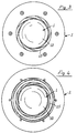
- Figure 5 shows a different diaphragm, indicated at 30, which is conceptually similar to that shown in figure 1, with the single modification related to the shape of the central pole shoe of the magnetic circuit since, above said pole shoe, under the diaphgram cap, there is arranged a solid member made of a non magnetic material which defines the profile at a small distance so as to provide a small volume compression chamber adapted to increase the stiffness of the movable assembly (without affecting the mechanical strength thereof), so as to provide a more even response through the overall range.
- the active surface of the diaphragm has a spherical cap shape having a base diameter of 34 mm, the weight of the movable portion of the diaphragm being 510 mgr.
- the diaphragm is made of an AlMg7 alloy, with a rubber damper on the peripheral ring member of the undulated portions; the movable coil has 30 turns, on two layers of copper wire of 0.12 mm diameter and, at 800 Hz, has an impedance of 8 ohm.
- the shown recording which relates to the transducer of figure 1, must be considered with great attention since the diagrams of substantially uneven configuration represent the responses obtained from the transducer of figure 2, which has not been modified, with diaphragms having a cap bending radius of respectively 23 and 29 mm.
- the subject diaphragm which is made of a single piece very thin blade member, provides great advantages with respect to conventional diaphragms, mainly with respect to the evenness of the characteristics of the single diaphragm portions.
Landscapes
- Engineering & Computer Science (AREA)
- Physics & Mathematics (AREA)
- Acoustics & Sound (AREA)
- Signal Processing (AREA)
- Multimedia (AREA)
- Audible-Bandwidth Dynamoelectric Transducers Other Than Pickups (AREA)
- Diaphragms For Electromechanical Transducers (AREA)
- Electrostatic, Electromagnetic, Magneto- Strictive, And Variable-Resistance Transducers (AREA)
Applications Claiming Priority (2)
| Application Number | Priority Date | Filing Date | Title |
|---|---|---|---|
| IT2046089 | 1989-05-11 | ||
| IT8920460A IT1229706B (it) | 1989-05-11 | 1989-05-11 | Diaframma per trasduttore elettroacustico, del tipo elettrodinamico a bobina mobile, per la conversione di segnali elettrici in suono e per la diffusione dello stesso |
Publications (3)
| Publication Number | Publication Date |
|---|---|
| EP0397621A2 EP0397621A2 (en) | 1990-11-14 |
| EP0397621A3 EP0397621A3 (en) | 1991-08-28 |
| EP0397621B1 true EP0397621B1 (en) | 1995-09-20 |
Family
ID=11167283
Family Applications (1)
| Application Number | Title | Priority Date | Filing Date |
|---|---|---|---|
| EP90830200A Expired - Lifetime EP0397621B1 (en) | 1989-05-11 | 1990-05-08 | Movable-coil electrodynamic transducer with a diaphragm |
Country Status (7)
| Country | Link |
|---|---|
| EP (1) | EP0397621B1 (it) |
| JP (1) | JPH0349500A (it) |
| CA (1) | CA2016478A1 (it) |
| DE (1) | DE69022474T2 (it) |
| DK (1) | DK0397621T3 (it) |
| ES (1) | ES2077665T3 (it) |
| IT (1) | IT1229706B (it) |
Families Citing this family (3)
| Publication number | Priority date | Publication date | Assignee | Title |
|---|---|---|---|---|
| WO2000013463A1 (en) * | 1998-08-31 | 2000-03-09 | Cytec Technology Corp. | Pitch carbon composite components for loudspeakers |
| ITBS20060008A1 (it) * | 2006-01-18 | 2007-07-19 | Outline Di Noselli G & C S N C | Rifasatore regolabileper driver a compressione ed altoparlanti a cupola a radiazione diretta. |
| JP5049883B2 (ja) * | 2008-06-02 | 2012-10-17 | ホシデン株式会社 | スピーカ |
Citations (1)
| Publication number | Priority date | Publication date | Assignee | Title |
|---|---|---|---|---|
| JPS5830297A (ja) * | 1981-08-17 | 1983-02-22 | Matsushita Electric Ind Co Ltd | ド−ム型スピ−カ |
Family Cites Families (5)
| Publication number | Priority date | Publication date | Assignee | Title |
|---|---|---|---|---|
| DE744830C (de) * | 1940-07-24 | 1944-11-21 | Klangfilm G M B H | Membran fuer Druckkammerlautsprecher |
| US2392143A (en) * | 1942-11-30 | 1946-01-01 | Rca Corp | Loud-speaker |
| DE2110466B1 (de) * | 1971-03-04 | 1971-11-18 | Standard Elek K Lorenz Ag | Hochtonlautsprecher |
| US3895671A (en) * | 1972-11-15 | 1975-07-22 | Nippon Musical Instruments Mfg | Method of manufacturing a thin sheet of beryllium or an alloy thereof |
| US3991286A (en) * | 1975-06-02 | 1976-11-09 | Altec Corporation | Heat dissipating device for loudspeaker voice coil |
-
1989
- 1989-05-11 IT IT8920460A patent/IT1229706B/it active
-
1990
- 1990-05-08 DK DK90830200.3T patent/DK0397621T3/da active
- 1990-05-08 DE DE69022474T patent/DE69022474T2/de not_active Expired - Fee Related
- 1990-05-08 ES ES90830200T patent/ES2077665T3/es not_active Expired - Lifetime
- 1990-05-08 EP EP90830200A patent/EP0397621B1/en not_active Expired - Lifetime
- 1990-05-10 CA CA002016478A patent/CA2016478A1/en not_active Abandoned
- 1990-05-11 JP JP2122505A patent/JPH0349500A/ja active Pending
Patent Citations (1)
| Publication number | Priority date | Publication date | Assignee | Title |
|---|---|---|---|---|
| JPS5830297A (ja) * | 1981-08-17 | 1983-02-22 | Matsushita Electric Ind Co Ltd | ド−ム型スピ−カ |
Also Published As
| Publication number | Publication date |
|---|---|
| IT8920460A0 (it) | 1989-05-11 |
| DE69022474D1 (de) | 1995-10-26 |
| ES2077665T3 (es) | 1995-12-01 |
| IT1229706B (it) | 1991-09-07 |
| CA2016478A1 (en) | 1990-11-11 |
| EP0397621A3 (en) | 1991-08-28 |
| DE69022474T2 (de) | 1996-05-23 |
| EP0397621A2 (en) | 1990-11-14 |
| JPH0349500A (ja) | 1991-03-04 |
| DK0397621T3 (da) | 1996-02-05 |
Similar Documents
| Publication | Publication Date | Title |
|---|---|---|
| US4933975A (en) | Dynamic loudspeaker for producing high audio power | |
| EP0422214B1 (en) | Self-cooled loudspeaker | |
| US2439665A (en) | Sound reproducing device | |
| US6222931B1 (en) | High power acoustical transducer | |
| US6111969A (en) | High fidelity, broad band acoustic loudspeaker | |
| US6320970B1 (en) | High frequency compression drivers | |
| US6993147B2 (en) | Low cost broad range loudspeaker and system | |
| US4395597A (en) | Speaker diaphragm assembly and a method of manufacturing the same | |
| US3059720A (en) | High frequency loudspeakers | |
| US3496307A (en) | Loudspeaker | |
| US5109424A (en) | Stereo headphones with plug, receptacle and securing plates | |
| JP2001086590A (ja) | 小型電気−音響変換器 | |
| US6721435B2 (en) | Acoustic loudspeaker with energy absorbing bearing and voice coil, and selective sound dampening and dispersion | |
| US3780232A (en) | Loudspeaker diaphragm | |
| KR950011498B1 (ko) | 분할된 진동판 부분을 갖는 광대역 스피커 | |
| US5933512A (en) | Double cone-type loudspeaker | |
| US3955055A (en) | Dynamic loudspeaker | |
| US6832106B2 (en) | Electroacoustic transducer | |
| US4823110A (en) | Tone generator with improved diaphragm mounting | |
| US2549091A (en) | Diaphragm for electroacoustic transducers | |
| US5757942A (en) | Speaker unit with an improved acoustic equalizer | |
| US3814857A (en) | Two-way loudspeaker system with two tandem-connected high-range speakers | |
| US4225757A (en) | Broad band dynamic loudspeaker | |
| US1962374A (en) | Acoustic device | |
| US5245669A (en) | Electroacoustic transducer |
Legal Events
| Date | Code | Title | Description |
|---|---|---|---|
| PUAI | Public reference made under article 153(3) epc to a published international application that has entered the european phase |
Free format text: ORIGINAL CODE: 0009012 |
|
| AK | Designated contracting states |
Kind code of ref document: A2 Designated state(s): CH DE DK ES FR GB LI NL SE |
|
| PUAL | Search report despatched |
Free format text: ORIGINAL CODE: 0009013 |
|
| AK | Designated contracting states |
Kind code of ref document: A3 Designated state(s): CH DE DK ES FR GB LI NL SE |
|
| 17P | Request for examination filed |
Effective date: 19911218 |
|
| 17Q | First examination report despatched |
Effective date: 19930625 |
|
| GRAA | (expected) grant |
Free format text: ORIGINAL CODE: 0009210 |
|
| AK | Designated contracting states |
Kind code of ref document: B1 Designated state(s): CH DE DK ES FR GB LI NL SE |
|
| REF | Corresponds to: |
Ref document number: 69022474 Country of ref document: DE Date of ref document: 19951026 |
|
| REG | Reference to a national code |
Ref country code: ES Ref legal event code: FG2A Ref document number: 2077665 Country of ref document: ES Kind code of ref document: T3 |
|
| PG25 | Lapsed in a contracting state [announced via postgrant information from national office to epo] |
Ref country code: SE Effective date: 19951220 |
|
| ET | Fr: translation filed | ||
| REG | Reference to a national code |
Ref country code: DK Ref legal event code: T3 |
|
| PLBE | No opposition filed within time limit |
Free format text: ORIGINAL CODE: 0009261 |
|
| STAA | Information on the status of an ep patent application or granted ep patent |
Free format text: STATUS: NO OPPOSITION FILED WITHIN TIME LIMIT |
|
| 26N | No opposition filed | ||
| PGFP | Annual fee paid to national office [announced via postgrant information from national office to epo] |
Ref country code: CH Payment date: 19970530 Year of fee payment: 8 |
|
| PG25 | Lapsed in a contracting state [announced via postgrant information from national office to epo] |
Ref country code: LI Free format text: LAPSE BECAUSE OF NON-PAYMENT OF DUE FEES Effective date: 19980531 Ref country code: CH Free format text: LAPSE BECAUSE OF NON-PAYMENT OF DUE FEES Effective date: 19980531 |
|
| REG | Reference to a national code |
Ref country code: CH Ref legal event code: PL |
|
| REG | Reference to a national code |
Ref country code: GB Ref legal event code: IF02 |
|
| PGFP | Annual fee paid to national office [announced via postgrant information from national office to epo] |
Ref country code: DE Payment date: 20020524 Year of fee payment: 13 |
|
| PGFP | Annual fee paid to national office [announced via postgrant information from national office to epo] |
Ref country code: DK Payment date: 20020527 Year of fee payment: 13 |
|
| PG25 | Lapsed in a contracting state [announced via postgrant information from national office to epo] |
Ref country code: DK Free format text: LAPSE BECAUSE OF NON-PAYMENT OF DUE FEES Effective date: 20031201 |
|
| PG25 | Lapsed in a contracting state [announced via postgrant information from national office to epo] |
Ref country code: DE Free format text: LAPSE BECAUSE OF NON-PAYMENT OF DUE FEES Effective date: 20031202 |
|
| REG | Reference to a national code |
Ref country code: DK Ref legal event code: EBP |
|
| PGFP | Annual fee paid to national office [announced via postgrant information from national office to epo] |
Ref country code: NL Payment date: 20060413 Year of fee payment: 17 |
|
| PGFP | Annual fee paid to national office [announced via postgrant information from national office to epo] |
Ref country code: ES Payment date: 20070404 Year of fee payment: 18 |
|
| PGFP | Annual fee paid to national office [announced via postgrant information from national office to epo] |
Ref country code: GB Payment date: 20070412 Year of fee payment: 18 |
|
| PG25 | Lapsed in a contracting state [announced via postgrant information from national office to epo] |
Ref country code: NL Free format text: LAPSE BECAUSE OF NON-PAYMENT OF DUE FEES Effective date: 20071201 |
|
| NLV4 | Nl: lapsed or anulled due to non-payment of the annual fee |
Effective date: 20071201 |
|
| PGFP | Annual fee paid to national office [announced via postgrant information from national office to epo] |
Ref country code: FR Payment date: 20070531 Year of fee payment: 18 |
|
| GBPC | Gb: european patent ceased through non-payment of renewal fee |
Effective date: 20080508 |
|
| REG | Reference to a national code |
Ref country code: FR Ref legal event code: ST Effective date: 20090119 |
|
| PG25 | Lapsed in a contracting state [announced via postgrant information from national office to epo] |
Ref country code: FR Free format text: LAPSE BECAUSE OF NON-PAYMENT OF DUE FEES Effective date: 20080602 |
|
| PG25 | Lapsed in a contracting state [announced via postgrant information from national office to epo] |
Ref country code: GB Free format text: LAPSE BECAUSE OF NON-PAYMENT OF DUE FEES Effective date: 20080508 |
|
| REG | Reference to a national code |
Ref country code: ES Ref legal event code: FD2A Effective date: 20080509 |
|
| PG25 | Lapsed in a contracting state [announced via postgrant information from national office to epo] |
Ref country code: ES Free format text: LAPSE BECAUSE OF NON-PAYMENT OF DUE FEES Effective date: 20080509 |