EP0397629A2 - Gesteinsbohrwerkzeug - Google Patents
Gesteinsbohrwerkzeug Download PDFInfo
- Publication number
- EP0397629A2 EP0397629A2 EP90850132A EP90850132A EP0397629A2 EP 0397629 A2 EP0397629 A2 EP 0397629A2 EP 90850132 A EP90850132 A EP 90850132A EP 90850132 A EP90850132 A EP 90850132A EP 0397629 A2 EP0397629 A2 EP 0397629A2
- Authority
- EP
- European Patent Office
- Prior art keywords
- tool
- shaft
- rock
- central hole
- saddle
- Prior art date
- Legal status (The legal status is an assumption and is not a legal conclusion. Google has not performed a legal analysis and makes no representation as to the accuracy of the status listed.)
- Ceased
Links
- 239000011435 rock Substances 0.000 title claims abstract description 16
- 239000007788 liquid Substances 0.000 claims abstract description 6
- 238000001816 cooling Methods 0.000 claims description 2
- 239000000110 cooling liquid Substances 0.000 abstract description 4
- 230000003247 decreasing effect Effects 0.000 description 2
- 238000011010 flushing procedure Methods 0.000 description 2
- 229910000831 Steel Inorganic materials 0.000 description 1
- 238000005096 rolling process Methods 0.000 description 1
- 239000010959 steel Substances 0.000 description 1
- 238000003466 welding Methods 0.000 description 1
Images

Classifications
-
- G—PHYSICS
- G01—MEASURING; TESTING
- G01B—MEASURING LENGTH, THICKNESS OR SIMILAR LINEAR DIMENSIONS; MEASURING ANGLES; MEASURING AREAS; MEASURING IRREGULARITIES OF SURFACES OR CONTOURS
- G01B11/00—Measuring arrangements characterised by the use of optical techniques
- G01B11/02—Measuring arrangements characterised by the use of optical techniques for measuring length, width or thickness
- G01B11/022—Measuring arrangements characterised by the use of optical techniques for measuring length, width or thickness by means of tv-camera scanning
-
- E—FIXED CONSTRUCTIONS
- E21—EARTH OR ROCK DRILLING; MINING
- E21B—EARTH OR ROCK DRILLING; OBTAINING OIL, GAS, WATER, SOLUBLE OR MELTABLE MATERIALS OR A SLURRY OF MINERALS FROM WELLS
- E21B10/00—Drill bits
- E21B10/08—Roller bits
- E21B10/10—Roller bits with roller axle supported at both ends
-
- E—FIXED CONSTRUCTIONS
- E21—EARTH OR ROCK DRILLING; MINING
- E21B—EARTH OR ROCK DRILLING; OBTAINING OIL, GAS, WATER, SOLUBLE OR MELTABLE MATERIALS OR A SLURRY OF MINERALS FROM WELLS
- E21B10/00—Drill bits
- E21B10/08—Roller bits
- E21B10/12—Roller bits with discs cutters
-
- E—FIXED CONSTRUCTIONS
- E21—EARTH OR ROCK DRILLING; MINING
- E21B—EARTH OR ROCK DRILLING; OBTAINING OIL, GAS, WATER, SOLUBLE OR MELTABLE MATERIALS OR A SLURRY OF MINERALS FROM WELLS
- E21B10/00—Drill bits
- E21B10/08—Roller bits
- E21B10/18—Roller bits characterised by conduits or nozzles for drilling fluids
Definitions
- the present invention relates to a rock working tool meant for mounting on the boring head of a tunnel boring machine.
- the tool comprises a cutter which with large force is pressed against a rock surface by the tunnel boring machine at the same time as the boring head is rotated.
- the present invention which is defined in the subsequent claim, aims at achieving a rock working tool which can be loaded substantially more than prior art tools because the tool is cooled during operation.
- fig 1 shows a rock working tool according to a first embodiment of the invention partly in section.
- Fig 2 shows an end view of the tool according to fig 1.
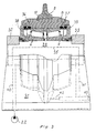
- Fig 3 shows a rock working tool according to a second embodiment of the invention partly in section.
- the tool shown in figs 1 and 2 comprises a saddle 1 which in a suitable way, e.g. welding along the edge 21, is secured to a not shown boring head of a tunnel boring machine.
- Two end pieces 2,3 are fastened to the saddle 1 by means of screws which are marked by lines 13,14.
- the end pieces 2,3 carry a shaft 4 which is provided with a central hole 5.
- Two rolling bearings 6,7 are mounted on shaft 4. These bearings carry a rotatable ring 8 on which a tool ring 9 is kept in place by a locking ring 10.
- Two seals in form of steel rings 11,12 are arranged between the rotatable ring 8 and end pieces 2,3 to prevent dirt from entering into the bearings 6,7.
- Saddle 1 and end pieces 2,3 are provided with channels 15,16,17 to convey cooling liquid to the central hole 5 and to flush cooling liquid on the tool ring 9 and the rotatable ring 8.
- a pressure liquid source 22 is arranged to feed cooling liquid to channel 15.
- the embodiment of the invention shown in fig 3, which is the preferred embodiment because of better cooling of the tool ring, comprises a saddle 31 which during operation of the rock working tool is mounted on the boring head of a tunnel boring machine.
- a shaft 34 is clamped to the saddle by means of two end pieces 32,33.
- a tool part 8,9 comprising a rotatable ring 8 and a tool ring 9 secured to the rotatable ring by a locking ring 10 is rotatably journalled by means of bearings 6,7 on shaft 34.
- Seals 36,37 are provided between seal holders 38,39 and the rotatable ring 8.
- Saddle 31 is provided with a channel 40 extending between a pressure liquid source 22 and shaft 34 for communication with the central hole 35.
- Saddle 31 is further provided with a channel 41 extending from shaft 34 to a channel 42 to convey liquid to channel 42 for flushing the tool ring 9.
- Channel 42 is closed at one end by a plug 43.
Landscapes
- Engineering & Computer Science (AREA)
- Geology (AREA)
- Life Sciences & Earth Sciences (AREA)
- Mining & Mineral Resources (AREA)
- Physics & Mathematics (AREA)
- Environmental & Geological Engineering (AREA)
- Fluid Mechanics (AREA)
- Mechanical Engineering (AREA)
- General Life Sciences & Earth Sciences (AREA)
- Geochemistry & Mineralogy (AREA)
- General Physics & Mathematics (AREA)
- Earth Drilling (AREA)
- Length Measuring Devices By Optical Means (AREA)
Applications Claiming Priority (2)
| Application Number | Priority Date | Filing Date | Title |
|---|---|---|---|
| SE8901625 | 1989-05-09 | ||
| SE8901625A SE463724B (sv) | 1989-05-09 | 1989-05-09 | Bearbetningsverktyg foer tunnelborrningsmaskin |
Publications (2)
| Publication Number | Publication Date |
|---|---|
| EP0397629A2 true EP0397629A2 (de) | 1990-11-14 |
| EP0397629A3 EP0397629A3 (de) | 1991-07-03 |
Family
ID=20375878
Family Applications (1)
| Application Number | Title | Priority Date | Filing Date |
|---|---|---|---|
| EP19900850132 Ceased EP0397629A3 (de) | 1989-05-09 | 1990-04-05 | Gesteinsbohrwerkzeug |
Country Status (7)
| Country | Link |
|---|---|
| US (2) | US5058690A (de) |
| EP (1) | EP0397629A3 (de) |
| JP (1) | JPH0363385A (de) |
| AU (1) | AU622547B2 (de) |
| CA (1) | CA2014765A1 (de) |
| SE (1) | SE463724B (de) |
| ZA (1) | ZA902771B (de) |
Families Citing this family (19)
| Publication number | Priority date | Publication date | Assignee | Title |
|---|---|---|---|---|
| BE1003136A3 (nl) * | 1990-03-23 | 1991-12-03 | Icos Vision Systems Nv | Werkwijze en inrichting voor het bepalen van een positie van ten minste een aansluitpen van een elektronische component. |
| CH682516A5 (de) * | 1991-02-13 | 1993-09-30 | Samro Bystronic Maschinen Ag | Verfahren und Vorrichtung zur Messung einer Dimension eines Körpers und Anwendung dieses Verfahrens. |
| US5326983A (en) * | 1993-06-30 | 1994-07-05 | Eastman Kodak Company | Storage phosphor cassette autoloader having cassette sensor |
| US5324957A (en) * | 1993-06-30 | 1994-06-28 | Eastman Kodak Company | Belt position sensor |
| US5451795A (en) * | 1994-04-28 | 1995-09-19 | Crathern & Smith, Inc. | Apparatus for spotting labels onto a surface having a transparent conveyor means |
| US5507565A (en) * | 1994-12-19 | 1996-04-16 | Eimco Coal Machinery, Inc. | Method and apparatus for suppressing dust and frictional ignition on a continuous mining machine |
| US5818594A (en) * | 1994-12-27 | 1998-10-06 | Lukander; Ronald | Method and apparatus for measuring the dimensions of three-dimensional objects such as chips used in pulp manufacture |
| US5659396A (en) * | 1995-06-07 | 1997-08-19 | Electrocom Automation L.P. | Dichotomous scan system for detection of edges of objects and overlapped objects having relatively uniform surfaces |
| JPH11148807A (ja) * | 1997-07-29 | 1999-06-02 | Toshiba Corp | バンプ高さ測定方法及びバンプ高さ測定装置 |
| US6521905B1 (en) * | 1999-09-22 | 2003-02-18 | Nexpress Solutions Llc | Method and device for detecting the position of a transparent moving conveyor belt |
| RU2168600C1 (ru) * | 1999-12-20 | 2001-06-10 | Ооо "Экобур" | Шарошечное гидромониторное долото |
| DE10022597B4 (de) * | 2000-05-10 | 2004-10-14 | Erhardt + Leimer Gmbh | Vorrichtung zum Erfassen der Randkante und/oder einer Markierung einer laufenden Warenbahn |
| US6405127B1 (en) | 2000-09-15 | 2002-06-11 | General Electric Company | Method for determining stationary locomotive location in a railyard |
| US7340084B2 (en) * | 2002-09-13 | 2008-03-04 | Sortex Limited | Quality assessment of product in bulk flow |
| US7394915B2 (en) * | 2005-09-16 | 2008-07-01 | Pitney Bowes Inc. | Method and system for measuring thickness of an item based on imaging |
| CN101045374B (zh) * | 2006-03-31 | 2011-05-11 | 海德堡印刷机械股份公司 | 用于对运动的物体的棱边进行图像摄取的方法及装置 |
| US20080236108A1 (en) * | 2007-03-29 | 2008-10-02 | Parmley Steven M | Package Wrapping Machine with Detection of Lip Features of Trayed Products to be Wrapped |
| US8643717B2 (en) * | 2009-03-04 | 2014-02-04 | Hand Held Products, Inc. | System and method for measuring irregular objects with a single camera |
| US8939369B2 (en) | 2011-01-24 | 2015-01-27 | Datalogic ADC, Inc. | Exception detection and handling in automated optical code reading systems |
Family Cites Families (17)
| Publication number | Priority date | Publication date | Assignee | Title |
|---|---|---|---|---|
| US1151104A (en) * | 1913-04-07 | 1915-08-24 | Granville A Humason | Drill. |
| US1130289A (en) * | 1913-06-20 | 1915-03-02 | Sharp Hughes Tool Company | Roller boring-drill. |
| US1532551A (en) * | 1920-06-18 | 1925-04-07 | Reed Roller Bit Co | Rotary deep-well-drilling apparatus |
| US2200482A (en) * | 1938-08-13 | 1940-05-14 | Winslow Charles Cecil | Rock bit |
| US3698769A (en) * | 1970-12-30 | 1972-10-17 | Lee Norse Co | Mining machine having liquid supply sealing means |
| US3679009A (en) * | 1971-02-02 | 1972-07-25 | Kennametal Inc | Rotary cutter for excavation, especially for use with raise boring and tunnel boring machines |
| US3897837A (en) * | 1974-03-05 | 1975-08-05 | Rapidex Inc | Boring apparatus |
| US4007799A (en) * | 1975-07-07 | 1977-02-15 | Smith International, Inc. | Raise drill with replaceable stem |
| US4063820A (en) * | 1975-11-10 | 1977-12-20 | Rca Corporation | Apparatus for measuring a dimension of an object |
| US4105925A (en) * | 1977-03-14 | 1978-08-08 | General Motors Corporation | Optical object locator |
| SU717326A1 (ru) * | 1978-10-20 | 1980-02-25 | Ордена Октябрьской Революции И Ордена Трудового Красного Знамени Институт Горного Дела Им. А.А.Скочинского | Исполнительный орган горного комбайна |
| US4363367A (en) * | 1981-10-26 | 1982-12-14 | Smith International, Inc. | Large diameter drill bit |
| DE3536171A1 (de) * | 1985-10-10 | 1987-04-16 | Gewerk Eisenhuette Westfalia | Querschneidkopf einer teilschnittmaschine mit innenbeduesung |
| US4705081A (en) * | 1986-02-21 | 1987-11-10 | Hewlett-Packard Company | System for sensing and forming objects such as leads of electronic components |
| US4803371A (en) * | 1987-09-30 | 1989-02-07 | The Coe Manufacturing Company | Optical scanning method and apparatus useful for determining the configuration of an object |
| US4929843A (en) * | 1989-06-28 | 1990-05-29 | General Electric Company | Apparatus and method for determining a dimension of an object |
| US4926917A (en) * | 1989-07-10 | 1990-05-22 | Eberhard Kirbach | Feed speed and guide arm control for sawing logs |
-
1989
- 1989-05-09 SE SE8901625A patent/SE463724B/sv not_active IP Right Cessation
-
1990
- 1990-04-05 EP EP19900850132 patent/EP0397629A3/de not_active Ceased
- 1990-04-11 ZA ZA902771A patent/ZA902771B/xx unknown
- 1990-04-18 CA CA002014765A patent/CA2014765A1/en not_active Abandoned
- 1990-04-18 JP JP2100542A patent/JPH0363385A/ja active Pending
- 1990-04-27 US US07/515,834 patent/US5058690A/en not_active Expired - Fee Related
- 1990-04-27 US US07/515,894 patent/US5013927A/en not_active Expired - Fee Related
- 1990-05-08 AU AU54793/90A patent/AU622547B2/en not_active Ceased
Also Published As
| Publication number | Publication date |
|---|---|
| SE8901625L (sv) | 1990-11-10 |
| AU5479390A (en) | 1990-11-15 |
| US5013927A (en) | 1991-05-07 |
| CA2014765A1 (en) | 1990-11-09 |
| ZA902771B (en) | 1992-02-26 |
| SE8901625D0 (sv) | 1989-05-09 |
| SE463724B (sv) | 1991-01-14 |
| JPH0363385A (ja) | 1991-03-19 |
| US5058690A (en) | 1991-10-22 |
| EP0397629A3 (de) | 1991-07-03 |
| AU622547B2 (en) | 1992-04-09 |
Similar Documents
| Publication | Publication Date | Title |
|---|---|---|
| EP0397629A2 (de) | Gesteinsbohrwerkzeug | |
| EP0052978B1 (de) | Schneidwerkzeug | |
| US5873423A (en) | Frustum cutting bit arrangement | |
| US4664567A (en) | Drill bit | |
| US6244665B1 (en) | Cutting toolholder with recessed groove for cutting tool removal | |
| US5220967A (en) | Drill and self-centering cutter insert therefor | |
| US4669786A (en) | Core breaker | |
| US11421482B2 (en) | Hole opener for directional drilling | |
| EP0720682A1 (de) | Scheibenförmiges schneidelement | |
| US3982595A (en) | Rock boring cutter with replaceable cutting elements | |
| US4915182A (en) | Cutter elements for hollow drill bit | |
| US4167980A (en) | Rock boring cutter with replaceable cutting element | |
| CA2306735C (en) | Grinding cup having optimized drive and/or contact surfaces | |
| US4488608A (en) | Rotary stone-cutting head with hardened teeth inserts | |
| WO2002066793A1 (en) | Tool head and tool for undercutting | |
| US4254995A (en) | Process of and an arrangement for mining | |
| CA2028361A1 (en) | Cutter bit assemblies and arrangements for use with mining or tunnelling machines | |
| CA2185058A1 (en) | Tunnel boring machine | |
| US5304020A (en) | Cutting tool for making cylindrical bores | |
| US4623155A (en) | Drill chuck with radial jaws | |
| US5104261A (en) | Tunnel boring machine | |
| US2765156A (en) | Rotary boring head assembly having radial arms and forwardly projecting cutter supports | |
| ZA200309220B (en) | Tool head and tool for mining of rock material. | |
| AU747836B2 (en) | Advancing device for boring sections of roadway, tunnels or similar | |
| CN212958620U (zh) | 一种具有防砂功能的截齿 |
Legal Events
| Date | Code | Title | Description |
|---|---|---|---|
| PUAI | Public reference made under article 153(3) epc to a published international application that has entered the european phase |
Free format text: ORIGINAL CODE: 0009012 |
|
| AK | Designated contracting states |
Kind code of ref document: A2 Designated state(s): AT CH DE FR GB IT LI SE |
|
| RAP1 | Party data changed (applicant data changed or rights of an application transferred) |
Owner name: ATLAS COPCO CONSTRUCTION AND MINING TECHNIQUE AB |
|
| PUAL | Search report despatched |
Free format text: ORIGINAL CODE: 0009013 |
|
| AK | Designated contracting states |
Kind code of ref document: A3 Designated state(s): AT CH DE FR GB IT LI SE |
|
| 17P | Request for examination filed |
Effective date: 19911223 |
|
| 17Q | First examination report despatched |
Effective date: 19921009 |
|
| STAA | Information on the status of an ep patent application or granted ep patent |
Free format text: STATUS: THE APPLICATION HAS BEEN REFUSED |
|
| 18R | Application refused |
Effective date: 19940130 |