EP0397723B1 - Filmvideospieler mit selektiver bildzusammenstellungssteuerung - Google Patents
Filmvideospieler mit selektiver bildzusammenstellungssteuerung Download PDFInfo
- Publication number
- EP0397723B1 EP0397723B1 EP89901404A EP89901404A EP0397723B1 EP 0397723 B1 EP0397723 B1 EP 0397723B1 EP 89901404 A EP89901404 A EP 89901404A EP 89901404 A EP89901404 A EP 89901404A EP 0397723 B1 EP0397723 B1 EP 0397723B1
- Authority
- EP
- European Patent Office
- Prior art keywords
- sensor
- film
- lens
- video player
- image
- Prior art date
- Legal status (The legal status is an assumption and is not a legal conclusion. Google has not performed a legal analysis and makes no representation as to the accuracy of the status listed.)
- Expired - Lifetime
Links
Images



Classifications
-
- H—ELECTRICITY
- H04—ELECTRIC COMMUNICATION TECHNIQUE
- H04N—PICTORIAL COMMUNICATION, e.g. TELEVISION
- H04N1/00—Scanning, transmission or reproduction of documents or the like, e.g. facsimile transmission; Details thereof
- H04N1/387—Composing, repositioning or otherwise geometrically modifying originals
- H04N1/3872—Repositioning or masking
-
- H—ELECTRICITY
- H04—ELECTRIC COMMUNICATION TECHNIQUE
- H04N—PICTORIAL COMMUNICATION, e.g. TELEVISION
- H04N1/00—Scanning, transmission or reproduction of documents or the like, e.g. facsimile transmission; Details thereof
- H04N1/04—Scanning arrangements, i.e. arrangements for the displacement of active reading or reproducing elements relative to the original or reproducing medium, or vice versa
- H04N1/19—Scanning arrangements, i.e. arrangements for the displacement of active reading or reproducing elements relative to the original or reproducing medium, or vice versa using multi-element arrays
- H04N1/195—Scanning arrangements, i.e. arrangements for the displacement of active reading or reproducing elements relative to the original or reproducing medium, or vice versa using multi-element arrays the array comprising a two-dimensional [2D] array
-
- H—ELECTRICITY
- H04—ELECTRIC COMMUNICATION TECHNIQUE
- H04N—PICTORIAL COMMUNICATION, e.g. TELEVISION
- H04N2201/00—Indexing scheme relating to scanning, transmission or reproduction of documents or the like, and to details thereof
- H04N2201/04—Scanning arrangements
- H04N2201/0402—Arrangements not specific to a particular one of the scanning methods covered by groups H04N1/04 - H04N1/207
- H04N2201/0404—Scanning transparent media, e.g. photographic film
-
- H—ELECTRICITY
- H04—ELECTRIC COMMUNICATION TECHNIQUE
- H04N—PICTORIAL COMMUNICATION, e.g. TELEVISION
- H04N2201/00—Indexing scheme relating to scanning, transmission or reproduction of documents or the like, and to details thereof
- H04N2201/04—Scanning arrangements
- H04N2201/0402—Arrangements not specific to a particular one of the scanning methods covered by groups H04N1/04 - H04N1/207
- H04N2201/0432—Adjusting the orientation of the scanning elements relative to the scanned sheet, e.g. changing from longitudinal to lateral scanning
Definitions
- the present invention relates generally to a film video player for generating a video signal from photographic film for display on a television monitor or receiver and for selective retention as by recording on a video recorder. More particularly, the invention relates to a film video player for generating a selectively composed video signal from photographic film by means of changing the magnification of the video image relative to the film frame image, of translating the video image relative to the film frame image and of rotating the video image relative to the film frame image.
- Apparatus for sensing photographic color films and for converting a sensed video image into a video signal is well known in the art. Since the development of relatively low cost, reliable solid state image sensors there has been considerable interest in the development of film video players for displaying color film images such as those present on color slides and color negatives on television monitors and receivers. Equipment has also been developed which contemplates the use of a photographic system including a printer with a film video player, wherein a film image is first displayed on a video monitor or receiver, a video image corresponding to only a portion of the film image is selectively displayed for composition purposes and an optical print of a portion of the film corresponding to the selected video image is made.
- a primary reason for the interest in composing selected video images constituting a portion of a film image is that the resolution of the commonly used photographic film formats is substantially greater than standard television resolution by factors of approximately four to ten times.
- the full available resolution of these film formats is not effectively used at normal magnification where the full frame film image substantially fills the solid state image sensor so that the video image effectively just fills the display of a television monitor or receiver.
- the excess resolution available in these film formats can be advantageously utilized by providing a film video player with means such as zoom optics for selectively changing the magnification of the video image and thus the displayed image with respect to the film image.
- the video image and resultant display constitutes only a portion of the film frame image, it is desirable to be able to effect relative vertical and horizontal translation between the film image and the video image. More advanced composing or editing functions can be carried out where it is possible to effect relative rotation between the film image and the video image.
- a common approach in the design of film video players of this type contemplates the use of fixed apparatus for mounting a slide or film negative presenting a film image and a fixed sensor spaced a distance therefrom along the optical axis of the system.
- a multi-group variable focal length lens Interposed between the fixed film image and fixed sensor is a multi-group variable focal length lens wherein one of the lens elements is movable axially along the optical axis to vary the focal length of the lens and thus provide a zoom capability.
- Multi-group variable focal length lenses of this type suffer the disadvantage that they are relatively expensive.
- Such multi-group variable focal length lenses normally require the driving of a plurality of substantially fixed cam surfaces to effect the zoom functions.
- cam surfaces are necessarily chosen to meet normal conditions for a particular system and cannot readily be altered or adjusted to accommodate manufacturing or assembly variations in variables such as the focal length of a particular lens or the exact plane where a film image or a sensor are mounted or oriented in a particular player.
- variables such as the focal length of a particular lens or the exact plane where a film image or a sensor are mounted or oriented in a particular player.
- attempts to eliminate variables of this nature which degradate the performance of a film video player can be accomplished only by expensive adjustment or customizing procedures which must be employed for each individual unit being manufactured.
- the production of film video players employing multi-group variable focal length lenses involves extreme expense in terms of both the cost of the components employed and the labor required for assembly and adjustment due to the necessity for an essentially customized installation.
- FR-A-2 551 237 describes a system for the scanning and reproduction of images wherein an original graphics image mounted on a carrier plate is moved in X and Y horizontal directions to effect scan of the original relative to the vertical optical axis of a camera lens and sensor mounted overhead and maintained in optical alignment. Magnification is varied by relative vertical displacement of the scanner, lens and carrier plate; and the lens/scanner camera assembly is made rotatable about the optical axis to vary the angle between the scanner and the original image.
- Film video player devices where the sensor may be moved horizontally and vertically for scan purposes and in some instances rotationally, have been employed in the art.
- mechanical complexities in effecting such motions while maintaining interconnections for the substantial circuitry which is required for transmitting a control signal for a solid state image sensor and for transmitting the video signals generated by a solid state sensor.
- Such known devices have not endeavored to approach the additional mechanical and electrical interconnect complexities which arise in a system where the sensor is required to carry out scanning functions in a plurality of perpendicularly displaced parallel planes as opposed to the known single plane of operation.
- an object of the present invention is to provide a film video player which is capable of generating a selectively composed video signal from a photographic film image by means of changing the magnification of the video image relative to the film frame image, of translating the video image relative to the film frame image and of rotating the video image relative to the film frame image, all the while maintaining the video image in focus.
- Another object of the present invention is to provide such a film video player which employs a simple, fixed focal length lens to effect the zoom or magnification functions.
- Yet another object is to provide such a film video player wherein the photographic film remains in a fixed position during imaging such that a wide variety of conventional equipment may be provided for effecting quick film change, such equipment including mounted slide containers, film strip holders and similar devices.
- a further object of the invention is to provide such a film video player wherein the lens and the image sensor at all times remain axially aligned although displaced from the optical axis of the apparatus to thereby preclude undesirable optical aberrations such as vignetting.
- Another object of the present invention is to provide film video player apparatus wherein a single mechanical assembly effects selective bidirectional rotation of the lens and sensor relative to the photographic film image as well as providing scanning or translating of the lens and sensor in one direction relative to the film image. Yet another object is to provide such a mechanical assembly wherein highly accurate positioning of the lens and sensor elements can be repeatedly effected. Yet a further object of the invention is to provide such an assembly which permits accurate placement of the sensor relative to the lens to maintain the film image in focus on the sensor at all displacements of the lens relative to the photographic film such that the video image remains in focus for all zoom conditions of the player.
- Yet another object of the invention is to provide film video player apparatus wherein the moving elements may be powered by accurate stepping motors.
- a still further object of the invention is to provide such a film video player wherein the mechanical assemblies employed may be of a type and design such that both minimum mechanical play and minimum interference can be realized.
- Still a further object of the invention is to provide such apparatus wherein the combination of mechanical structure and electrical drive elements is such as to permit accurate, repeatable performance of the apparatus and the employment of a wide variety of types of control systems therefor depending upon the operating parameters for a particular application.
- the present invention contemplates a film video player having gates mounting photographic film in relation to imaging mechanism having a lens for projecting at least a portion of a film frame image on a sensor which converts a sensor image to a video signal for video display including zoom mechanism for changing the magnification of the sensor image with respect to the film frame image, scan mechanism for translating the sensor with respect to the film frame image in a first direction, and a gear assembly for translating the sensor with respect to the film frame image in a second direction perpendicular to the first direction and for rotating the sensor with respect to the film frame image.
- Exemplary film video player apparatus embodying the concepts of the present invention is generally indicated by the numeral 10 in Fig. 1 of the drawings.
- the film video player includes an optical system, generally indicated by the numeral 11, including light source optics, generally indicated by the numeral 12.
- the light source optics 12 are shown diagramatically in Fig. 1 and have elements and characteristics which are generally well known to persons skilled in the art.
- the light source optics 12 are shown to include a lamp 13 which may be one of various types of high intensity lamps which provides a light source for illuminating a film gate.
- the film gates 14 and 15 respectively mount photographic film F and F' therein which may carry a color image constituting the film image for the film video player system 10.
- the film gates 14, 15 may be suitably adapted to receive slides in one gate and film strips at a second gate. Alternatively, it is to be appreciated that more or less gates could be provided for more or less types of photographic film. As a further alternative, various film formats might be presented at a single film gate.
- a diffuser 16 Interposed between the lamp 13 and the film gates 14, 15 is a diffuser 16 which is adapted to improve the uniformity of the illumination from lamp 13, impinging upon the film gates 14, 15.
- the light source optics 12 may also include a mask 17 which limits the size of the source image emanating from the film F and F' positioned in the film gates 14, 15. It will also be appreciated by persons skilled in the art that depending upon the type of light source employed, appropriate filters, choppers and attenuators may be employed to provide a light source having a range of intensities and uniformity sufficient to meet the desired operating characteristics of a particular film video player 10.
- the optical system 11 has the elements of the light source optics 12 centered upon an optical axis A of the film video player. 10.
- the optical axis A also has positioned thereon at a variable distance from the film gates 14, 15 a fixed focal length lens L.
- an aperture mechanism 18 which may be designed according to known parameters for conformance with operatively interrelated elements of apparatus 10.
- an image sensor S Displaced to the other side of the lens L from the aperture mechanism 18 is an image sensor S upon which the film image is directed by the lens L.
- the image sensor S may be a charge coupled device (CCD) of any of various types which are well known in the art and which produce a video signal as an output.
- CCD charge coupled device
- CCD image sensors produce from an impinging color image a color video signal which may equal or exceed standard television resolution. It will be appreciated by persons skilled in the art that other types of video sensors may be employed depending upon particular applications for a film video player 10.
- the elements of the light source optics 12 in addition to being centered upon optical axis A are also stationary or fixedly mounted axially of the optical axis A.
- the lens L and the image sensor S are mounted in a manner hereinafter described to permit the independent motion of each axially along the optical axis A.
- the lens L and the sensor S are mounted to permit selective scan or translation in all directions and rotation in any plane perpendicular to the optical axis A within the limits of travel of the lens L and sensor S axially of the optical axis A.
- the film video player 10 has as a primary structural member supporting lens L and sensor S a base, generally indicated by the numeral 20.
- the base 20 is rigidly mounted with respect to conventional mounting elements (not shown) for the light source optics 12.
- the base 20 has a generally rectangular bottom platform 21 with the longitudinal dimension thereof paralleling the optical axis A.
- the base 20 has upturned supports 22 at the longitudinal extremities (see Fig. 1) and an upturned support 23 along one longitudinal side thereof (see Figs. 1-4).
- the lens L and image sensor S are jointly movable axially of the optical axis A and longitudinally relative to the base 20 by virtue of the structural interrelation with a zoom carriage, generally indicated by the numeral 25.
- the zoom carriage 25 has a generally rectangular cupped configuration bounded on the sides extending longitudinally of the base 20 by upstanding walls 26 and 27 (Fig. 2).
- the carriage 25 has at its longitudinal extremities proximate the light source optics 12, an upstanding wall 28 and at the opposite longitudinal extremity a substantially higher upstanding wall 29 (Fig. 1).
- the zoom carriage 25 is mounted for movement longitudinally of the base 20 on a zoom rod 30 which extends the length of the base 20, between upturned supports 22, and preferably proximate and paralleling upturned support 23.
- the zoom rod 30 may be secured relative to the base 20 as by a head 31 or enlarged diameter portion at one extremity thereof and a retainer 32 at the opposite extremity thereof.
- the zoom carriage 25 is physically attached to the zoom rod 30 by a pair of rod receivers, generally indicated by the numerals 35 and 36.
- the rod receivers 35, 36 may be identical and project laterally outwardly of upstanding wall 26 preferably proximate the extremities thereof as best seen in Fig. 3.
- Each of the rod receivers 35, 36 consists of a mounting block 38 which may be provided with a reinforcing rib 39.
- the mounting block 38 has a downwardly directed U-shaped channel 40 which is adapted to receive a bushing 41 which receives a zoom rod 30.
- the bushing 41 is maintained within U-shaped channel 40 by a bushing retainer plate 42 which may be selectively attached to zoom carriage 25 as by a fastener 43.
- zoom carriage 25 mounts preferably substantially underlying wall 27 one or more rounded glides 44 (Fig. 2) which slidably engage platform 21 of base 20. It will be understood that wheels or other friction reducing members may be employed in lieu of glides 44. It will thus be appreciated that the zoom carriage 25 moves longitudinally relative to the base 20 by virtue of the bushings 41 within the rod receivers 35, 36 slidably engaging the zoom rod 30 and the glides 44 slidably engaging platform 21.
- the zoom carriage 25 is driven along and selectively precisely located axially of zoom rod 30 by a zoom carriage drive assembly, generally indicated by the numeral 45.
- the drive assembly 45 consists of a zoom motor 46 which is preferably a stepper motor of a type which can be advanced with suitable known controls through selected numbers of highly accurate angular increments.
- the zoom motor 46 may conveniently be mounted on the upturned support 23 of base 20 and have a shaft 47 which mounts a zoom motor pulley 48.
- the zoom motor 46 is preferably mounted on upturned support 23 proximate one end of the base 20 with an idler pulley 49 mounted proximate the opposite longitudinal end of the base 20 (Fig. 1). the pulleys 48, 49 preferably have teeth 50 (Fig.
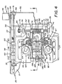
- the zoom carriage 25 is displaced longitudinally of base 20 on zoom rod 30 by a belt retaining assembly, generally indicated by the numeral 55, interconnected with the timing belt 51, as best seen in Figs. 2, 4, and 5.
- the belt retaining assembly 55 has a drive plate 56 which may be attached outwardly of upstanding wall 26 of zoom carriage 25.
- the drive plate 56 may have a reinforcing rib 57 positioned thereunder.
- the timing belt 51 has, as seen in Figs. 1, 2 and 5, an upper reach 51' and a lower reach 51''.
- the upper reach 51' of belt 51 is positioned just above the drive plate 56 which has teeth 58 which matingly engage with the teeth 52 interiorly of the timing belt 51.
- the upper reach 51' of belt 51 is maintained in interlocking engagement with the drive plate 56 of carriage 25 by virtue of one or more guide plates 60.
- the guide plates 60 are attached to wall 26 and may have reinforcing ribs 61 thereabove in a manner similar to the mounting of the drive plate 56.
- there are two guide plates 60 positioned longitudinally of zoom carriage 25 just beyond the extremities of drive plate 56 and displaced thereabove a distance of approximately the thickness of timing belt 51.
- the guide plates 60 have a smooth lower guide surface 61 which engages the outer surface of timing belt 51 and thus maintains the timing belt 51 in engagement with the drive plate 56 so that the zoom carriage 25 is linearly displaced the exact distance that timing belt 51 is displaced by zoom motor 46.
- the arrangement of the drive plate 56 and guide plates 60 is such that the timing belt 51 remains engaged with drive plate 56 despite possible variations in belt tension, while permitting the replacement of timing belt 51 when necessary.
- the lens L and image sensor S are jointly translatable or scannable in one direction in an infinite number of planes perpendicular to optical axis A by virtue of structural interrelation with a scan carriage, generally indicated by the numeral 65.
- the scan carriage 65 is of a generally L-shaped configuration having a flat base 66 and a somewhat cup-shaped upstanding portion 67.
- the flat base 66 may repose in a cutout 68 in the zoom carriage 25 to facilitate the achievement of a compact design for the film video player 10.
- the scan carriage 65 is movable laterally or horizontally of the zoom carriage 25 by a scan drive assembly, generally indicated by the numeral 70.
- the upstanding wall 29 of zoom carriage 25 mounts a yoke 71 in which a worm shaft 72 having teeth 73 is journaled.
- the yoke 71 may, for example, mount spaced bearings 74 which support the worm shaft 72. Rings 74' or other retainers may be positioned on the worm shaft 72 proximate the bearings 74.
- the cup-shaped upstanding portion 67 of scan carriage 65 has preferably substantially medially vertically thereof a rearwardly directed C-shaped receiver 75 (Fig. 1).
- the C-shaped receiver 75 mounts a pair of spaced bushings 76 which receive the worm shaft 72.
- the C-shaped receiver 75 has interposed between the bushings 76 a toothed drive plate 77 which matingly engages the teeth 73 of worm shaft 72.
- a shaft retainer 78 which may also be C-shaped interfits with the C-shaped receiver 75 to effect retention of the bushings 76 and thus maintain the worm shaft 72 and teeth 73 thereof in engagement with the toothed drive plate 77. It will thus be appreciated that rotation of the worm shaft 72 will effect the displacement of the scan carriage 65 axially of the worm shaft 72 and therefore laterally of the zoom carriage 25 and base 20.
- the scan drive assembly 70 effects rotation of the worm shaft 72 through actuation of a scan motor 80 shown in Figs. 1 and 3.
- the scan motor 80 may conveniently be mounted on zoom carriage 25 on an upstanding wall 81 thereof.
- the scan motor 80 may be a stepper motor possessing characteristics comparable to zoom motor 46.
- the scan motor 80 mounts a drive pulley 82 which carries a timing belt 83, which may be comparable to the timing belt 51, that engages a driven pully 84 which is nonrotatably affixed to the worm shaft 72.
- the scan motor 80 may be selectively driven in two directions to effect rotation of the worm shaft 72 to position the bushings 76 and drive plate 77 and thus the scan carriage 65 at any desired location along worm shaft 72 within the confines of the yoke 71 and thus laterally relative to zoom carriage 25.
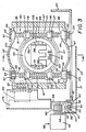
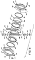
- the lens L and image sensor S are jointly translatable or scannable in a direction perpendicular to the direction of movement of scan carriage 65, in this instance vertically, and rotated in an infinite number of planes perpendicular to optical axis A by virtue of structural interrelation with a gear assembly, generally indicated by the numeral 90 in Figs. 1, 3, 4 and 6.
- the gear assembly 90 includes a pair of worm shafts 91 and 92.
- the worm shafts 91, 92 are mounted in the cup-shaped upstanding portion 67 of scan carriage 65 such as to be fixed spaced parallel relation.
- the cup-shaped portion 67 of scan carriage 65 has integral bearing seats 93 in which each extremity of each of the worm shafts 91 and 92 is supported.
- each extremity of each of worm shafts 91, 92 is supported by ball bearings 94, which repose within each of the bearing seats 93, to permit free rotation of the worm shafts 91 and 92.
- the bearings 94 may be retained in the bearing seats 93 as by C-rings 95 which are positioned in grooves 96 proximate each extremity of each of the worm shafts 91, 92.
- annular compliant member 97 may be positioned at one end of each of the worm shafts 91, 92 axially outwardly of the bearings 94 and within the confines of the bearing seats 93.
- Each of the worm shafts 91, 92 have helical threads 98 disposed over a substantial portion of the length thereof between the axially spaced bearings 94.
- the helical threads 98 of each of the worm shafts 91, 92 may be of conventional design with both having either right-hand or left-hand threads for reasons which will become apparent hereinafter.
- the gear assembly 90 has interposed between and operatively coacting with worm shafts 91, 92 a worm gear mechanism, generally indicated by the numeral 100.
- a worm gear mechanism 100 Central to the worm gear mechanism 100 is a worm gear 101 which has a diameter such that the teeth 102 thereof matingly engage with the helical threads 98 of each of the worm shaft 91, 92 when worm gear 101 is juxtapositioned therebetween, as best seen in Fig. 3.
- the worm gear mechanism 100 may have a bearing assembly 103 positioned axially to either side of the worm gear 101.
- each bearing assembly 103 may include a pair of bearing races 104 which encapsulate ball bearings 105 therebetween.
- a clamshell housing having a pair of identical cup-shaped halves 111' and 111'' encapsulates the worm gear 101 and the bearing assemblies 103. Additionally, an annular compliant member 112 may be disposed axially outwardly of each of the bearing assemblies 103 and constrained within the halves 111', 111'' of the clamshell housing 100 to provide an extent of resilience to the mounting of worm gear 101 within housing 110.
- the halves 111', 111'' may be selectively joined and separated by removable fasteners such as machine screws 113 and complementary nuts 114.
- the cup-shaped halves 111', 111'' of clamshell housing 110 each have a pair of projecting ears 115 which are U-shaped in cross-section and which, when the halves 111', 111'' are joined, form bores which clear the worm shafts 91, 92.
- the worm shafts 91 and 92 are each journaled in the housing 110 in bushings 116 which are preferably positioned near the vertical top and bottom of each of the ears 115 of the housing 110.
- the bushings 116 may each have an increased diameter portion 117 which engages grooves 118 proximate the vertical extremities of the ears 115.
- a reversal of the direction of rotation of each of the worm shaft 91, 92 would produce rotation of the worm gear 101 in the opposite direction.
- a controlled vertical translation distance and bidirectional rotation of the worm gear 101 through desired angles may be achieved.
- the worm shafts 91, 92 of gear assembly 90 are independently driven by a worm shaft drive assembly, generally indicated by the numeral 120.
- the worm shaft drive assembly 120 consists of stepper motors 121 and 122 which selectively directionally rotationally drive the worm shafts 91 and 92, respectively.
- the stepper motors 121, 122 may be mounted on the flat base 66 of scan carriage 65 displaced a distance from the bearing seats 93 in cup-shaped upstanding portion 67 of scan carriage 65 (Figs. 1 and 2).
- Each of the stepper motors 121 and 122 mounts a drive pulley 123 which carries a timing belt 124 (Figs. 1 and 4).
- the timing belt 124 also engage pulleys 125 which are nonrotationably attached to extensions 91' and 92' of the worm shafts 91 and 92 extending through the bearing seats 93 in the lower extremity of portion 67 of scan carriage 65 (Figs. 1, 3 and 6). It will thus be appreciated that controlled, drive of stepper motors 121 and 122 will effect rotations of the worm shafts 91 and 92, respectively, to produce a desired extent of rotation in a desired direction. As previously detailed this controlled rotation of shafts 91, 92 provides the controlled vertical translation and bidirectional rotation of the worm gear 101 which is transmitted to the lens L and image sensor S.
- the worm gear 101 is thus driven by the just described rotational and vertical translating or scanning motion imparted by rotation of worm shafts 91, 92, the horizontal translation or scanning imparted by the horizontal movement of scanning carriage 65 carrying the worm shaft gear assembly 90, and the motion of the zoom carriage 25 carrying the scanning carriage 65 relative to the base 20. These combined motions are transmitted to a lens box assembly generally indicated by the numeral 130. As best seen in Figs. 3 and 4, the lens box assembly is attached centrally of the worm gear 101 of the worm gear mechanism 100. As shown, the worm gear has a pair of diametrically opposed sector plates 131, 131 which extend into the otherwise circular aperture 132 in the worm gear 101.
- the lens box assembly 130 is an elongated rectangular structure having, as seen in Figs. 1 and 4, a lens support portion 135, a gear engagement portion 136, and a motor retainer portion 137. As best seen in Fig. 4, the lens support portion 135, the gear engagement portion 136 and the motor retainer portion 137 are spaced and joined by a pair of parallel side plates 138, 138. The side plates 138 in the vicinity of gear engagement portion 136 are spaced a distance such as to interfit within and engage the sector plates 131, 131 of worm gear 101.
- a pair of flanges 140, 140 extend outwardly of the side plates 138 and therefore overlie and may substantially conform to the configuration of the sector plates 131.
- the flanges 140 are attached to the sector plates 131 as by suitable fasteners such as machine screws (not shown).
- the lens support portion 135 of lens box assembly 130 is provided with suitable elements for mounting a lens L of whatever type is to be employed in the film video player apparatus 10. It will be understood that for different configurations of a lens L and aperture mechanism 18, different structural elements may be required to effect the necessary mounting and alignment.
- the sensor S is affixed to a sensor carriage 145 which includes suitable elements for mounting and aligning a particular sensor to be employed in the film video player apparatus 10.
- the sensor carriage 145 may also contain suitable mounting elements for carrying other elements such as one or more filters 146 which may be advantageously mounted in proximity to the sensor S.
- the sensor S is necessarily positioned a different distance from the lens L for every different distance reflecting magnification between the lens L and the source image originating at the film gates 14 and 15, as may be established by movement of zoom carriage 25. This adjustment of the distance between the sensor S and lens L is affected by moving the sensor carriage 145 relative to the lens L and other elements of lens box assembly 130.
- the sensor carriage 145 has a projecting hub 147 which has a through bore 148 therein.
- the through bore 148 seats proximate each axial extremity thereof bushings 149 which receive a carriage support rod 150.
- the carriage support rod 150 is attached to lens box assembly 130 and particularly may be interconnected between the lens support portion 135 and the gear engagement portion 136 thereof (Fig. 1).
- a sensor carriage drive assembly generally indicated by the numeral 155.
- the sensor carriage drive assembly 155 is powered by a sensor carriage stepper motor 156 which may be of the type employed as the zoom motor 46.
- the stepper motor 156 may be supported on the lens box assembly 130 and particularly may be supported to the rear of the extent of travel of sensor carriage 145 and particularly between the gear engagement portion 136 and motor retainer portion 137 of lens box assembly 130.
- the sensor carriage stepper motor 156 has a shaft 157 which mounts a drive pulley 158 having teeth 159.
- the lens support portion 135 of lens box 130 mounts an idler pulley 160 having teeth 161.
- the teeth 159, 161 of the pulleys 158 and 160 respectively, engage a timing belt 165 of the type employed in conjunction with the zoom carriage drive assembly 45.
- the sensor carriage 145 is attached to the timing belt 165 as by means of a slot 166 which may be positioned in the hub 147 of the sensor carriage 145 (Fig. 2).
- the slot 166 may be appropriately grooved to matingly engage teeth on the timing belt 165 in a manner similar to drive plate 46 shown in Fig. 5. to insure positive linear movement of the sensor carriage 145 along carriage support rod 150 for each linear increment of movement of the time belt 165 as produced by controlled angular travel of the stepper motor 156.
- Figs. 1 and 2 depict an exemplary flexible circuit, generally indicated by the numeral 170, consisting of a cable 171 having a connecting portion 172 proximate one extremity attached to the sensor S of sensor carriage 145 (Fig. 2) and having an opposite extremity 173 which may be attached to a signal processing board 174 (Figs. 1-3) which may be mounted on a portion of the zoom carriage 25 of film video player 10.
- the connecting portion 172 of flexible cable 170 is adapted to be supported by an upstanding cable mount 180 affixed to sensor carriage 145 to which connecting portion 172 may be selectively attached as by a machine screw 181 or other fastener.
- the connecting portion 172 extends about a portion of the circumference of sensor S and has an extremity 172' which is attached to a standoff bracket 182 projecting from sensor carriage 145 as by a machine screw 183 or other fastener (Fig. 2).
- flexible cable 170 may be both mechanically and electrically interconnected with sensor S by virtue or a projecting tab 172'' as seen in Figs. 1 and 2. Details of an interconnection of tab 172'' with sensor S are set forth in U.S. Patent 4,811,107, "Video Player Sensor Cable", issued March 7, 1989.
Landscapes
- Engineering & Computer Science (AREA)
- Multimedia (AREA)
- Signal Processing (AREA)
- Facsimile Scanning Arrangements (AREA)
- Facsimiles In General (AREA)
- Facsimile Heads (AREA)
Claims (21)
- Elektronisches Filmabtastgerät mit Mitteln zur Halterung eines fotografischen Films relativ zur optischen Achse (A) einer Abbildungseinrichtung, die ein Objektiv zum Projizieren mindestens eines Teils eines Filmbildes auf einen Bildsensor aufweist, der das empfangene Bild in ein Videosignal für die Videobildwiedergabe umwandelt, einer Einrichtung zur Änderung des Projektionsbildmaßstabs, Mitteln zur Querbewegung des Bildsensors in einer ersten Richtung parallel zur Filmbildebene, Mitteln zur Querbewegung des Bildsensors in einer zweiten zur ersten Richtung senkrechten Richtung parallel zur Filmbildebene, und Mitteln zur Drehung des Bildsensors um die optische Achse relativ zum Filmbild, dadurch gekennzeichnet, daß das Objektiv (L) eine Festbrennweite besitzt, und daß die Einrichtung zur Änderung des Projektionsbildmaßstabs Mittel (25, 45) aufweist, mit denen der Abstand zwischen Objektiv und fotografischem Film veränderbar ist, um einen geforderten Abbildungsmaßstab zu erhalten, und Mittel (130, 145, 155), mittels derer der Abstand zwischen Bildsensor (S) und Objektiv derart verändert wird, daß bei jedem gewählten Abbildungsmaßstab das vom Bildsensor empfangene Projektionsbild scharfgestellt ist.
- Filmabtastgerät nach Anspruch 1, gekennzeichnet durch ein Unterteil (20) zur Aufnahme des fotografischen Films und des Objektivschlittens (25), der relativ zum Unterteil bewegbar ist und das Objektiv trägt.
- Filmabtastgerät nach Anspruch 1, dadurch gekennzeichnet, daß die Mittel zur Veränderung des Abstands zwischen Bildsensor und Objektiv einen Sensorschlitten (145) für die axiale Bewegung des Bildsensors relativ zum Objektiv aufweisen.
- Filmabtastgerät nach Anspruch 1, dadurch gekennzeichnet, daß das Objektiv und der Bildsensor in einem Objektivtubus (130) angeordnet und axial ausgerichtet sind.
- Filmabtastgerät nach Anspruch 1, dadurch gekennzeichnet, daß die Mittel zur Querbewegung des Bildsensors relativ zum Filmbild einen Querschlitten (65) aufweisen.
- Filmabtastgerät mit Mitteln zur Halterung eines fotografischen Films relativ zur optischen Achse (A) einer Abbildungseinrichtung, die ein Objektiv zum Projizieren mindestens eines Teils eines Filmbildes auf einen Bildsensor aufweist, der das empfangene Bild in ein Videosignal für die Videobildwiedergabe umwandelt, einer Einrichtung zur Änderung des Projektionsbildmaßstabs, Mitteln zur Querbewegung des Bildsensors parallel zur Filmbildebene, und Mitteln zur Drehung des Bildsensors um die optische Achse relativ zum Filmbild, dadurch gekennzeichnet, daß die Mittel zur Querbewegung und Drehung des Bildsensors eine Getriebeanordnung (90) mit einem Getrieberad (100) aufweisen, mit dem der Bildsensor (S) verbunden ist, wobei das Getrieberad ein Schneckenrad (100) ist, das mittels Schneckenwelle (91, 92, 120) antreibbar ist.
- Filmabtastgerät nach Anspruch 6, dadurch gekennzeichnet, daß das Schneckengetriebe zwei Schneckenwellen (91, 92) aufweist, die parallel und im Abstand voneinander angeordnet sind und in Wirkverbindung mit dem Schneckenrad stehen.
- Filmabtastgerät nach Anspruch 7, dadurch gekennzeichnet, daß die Schnecken der Schneckenwellen gleichen Richtungssinn aufweisen sowie Mittel (121, 122) zu deren Drehung vorgesehen sind, wobei durch Drehung der Schneckenwellen in jeweils gleicher Richtung eine Querbewegung und durch Drehung in jeweils entgegengesetzten Richtungen eine Rotation des Bildsensors relativ zum Filmbild bewirkt wird.
- Filmabtastgerät nach Anspruch 7, dadurch gekennzeichnet, daß ein Gehäuse (110) das Schneckenrad und jeweils einen Abschnitt der Schneckenwellen derart umschließt, daß sie in getrieblicher Wirkverbindung miteinander gehalten sind.
- Filmabtastgerät nach Anspruch 9, dadurch gekennzeichnet, daß das Schneckenrad durch beidseitig angeordnete Axiallager im Gehäuse gelagert ist.
- Filmabtastgerät nach Anspruch 7, dadurch gekennzeichnet, daß das Gehäuse ein Schalengehäuse (111) mit Vorsprüngen (115) ist, welche die Lagerbuchsen (116) für die Schneckenwellen enthalten.
- Filmabtastgerät nach Anspruch 11, dadurch gekennzeichnet, daß die Schneckenwellen mittels Schrittschaltmotoren (121, 122) und Zahnriemen (124) unabhängig voneinander antreibbar sind.
- Filmabtastgerät nach Anspruch 6, dadurch gekennzeichnet, daß die Getriebeanordnung einen Objektivtubus (130) zur Halterung des Bildsensors und des Objektivs trägt, welche beide sowohl querbeweglich als auch rotatorisch zum Filmbild angeordnet sind.
- Filmabtastgerät nach Anspruch 13, dadurch gekennzeichnet, daß der Bildsensor auf einem Sensorschlitten (145) angeordnet ist, der in axialer Richtung relativ zum Objektiv bewegbar ist.
- Filmabtastgerät nach Anspruch 14, dadurch gekennzeichnet, daß der Sensorschlitten auf einer Führungsstange (150) angeordnet ist, die am Objektivtubus angebracht ist, und daß ein am Sensorschlitten befestigter Zahnriemen (165) von einem Schrittschaltmotor (156) zur wahlweisen Positionierung des Sensorschlittens entlang der Führungsstange antreibbar ist.
- Filmabtastgerät nach Anspruch 6, gekennzeichnet durch Bewegungsmittel (65, 70) zur Querbewegung des Bildsensors parallel zur Filmbildebene in einer Richtung, die von der vom Getriebe vorgegebenen Richtung abweicht.
- Filmabtastgerät nach Anspruch 16, dadurch gekennzeichnet, daß auf der Einrichtung zur Änderung des Bildmaßstabs des vom Bildsensor empfangenen Bildes ein eine Schneckenwelle (72) tragendes Joch (71) angeordnet ist, und daß die Bewegungsmittel ein Eingriffselement (77) aufweisen, das mit der Schneckenwelle kämmt.
- Filmabtastgerät nach Anspruch 17, dadurch gekennzeichnet, daß die Schneckenwelle zur Verschiebung des Querschlittens mittels eines durch einen Schrittschaltmotor (80) getriebenen Zahnriemens (83) angetrieben wird.
- Filmabtastgerät mit Mitteln zur Halterung eines fotografischen Films relativ zur optischen Achse (A) eines Beleuchtungssystems, das ein Objektiv zum Projizieren mindestens eines Teils eines Filmbildes auf einen Bildsensor aufweist, der das empfangene Bild in ein Videosignal umwandelt, Mitteln zum Ändern des Projektionsbildmaßstabs, Mitteln zur Querbewegung des Bildsensors in einer ersten Richtung parallel zum Filmbildebene, Mittel zur Querbewegung des Bildsensors in einer zweiten zur ersten Richtung senkrechten Richtung parallel zur Filmebene, und Mitteln zur Drehung des Bildsensors und des Objektivs um die optische Achse relativ zum Filmbild, dadurch gekennzeichnet, daß das Objektiv (L) eine Festbrennweite besitzt, daß die Mittel zur Querbewegung des Bildsensors (S) in der zweiten Richtung sowie die Mittel zur Drehung des Bildsensors mit Mitteln zur gemeinsamen Querbewegung und Drehung sowohl des Bildsensors als auch des Objektivs versehen sind, und daß die Mittel zur Änderung des Projektionsbildmaßstabs einen relativ zum Unterteil (29) bewegbaren Objektivschlitten (25) aufweisen, mittels dessen das Objektiv in unterschiedlichen Abständen zum Filmbild positionierbar ist, sowie Mittel (130, 145, 155), mittels derer der Abstand zwischen Bildsensor und Objektiv derart verändert wird, daß bei jedem gewählten Abbildungsmaßstab das vom Bildsensor empfangene Projektionsbild scharfgestellt ist.
- Filmabtastgerät nach Anspruch 19, dadurch gekennzeichnet, daß die Mittel zum Verändern des Abstands zwischen Bildsensor und Objektiv einen Sensorschlitten (145) aufweisen, auf dem der Bildsensor für eine axiale Bewegung relativ zum Objektiv angeordnet ist.
- Filmabtastgerät nach Anspruch 19, dadurch gekennzeichnet, daß Objektiv und Bildsensor im Objektivtubus (130) angeordnet und axial zueinander ausgerichtet sind.
Applications Claiming Priority (2)
| Application Number | Priority Date | Filing Date | Title |
|---|---|---|---|
| US07/143,661 US4819073A (en) | 1988-01-13 | 1988-01-13 | Film video player apparatus with selective image composing controls |
| US143661 | 1988-01-13 |
Publications (2)
| Publication Number | Publication Date |
|---|---|
| EP0397723A1 EP0397723A1 (de) | 1990-11-22 |
| EP0397723B1 true EP0397723B1 (de) | 1993-12-08 |
Family
ID=22505033
Family Applications (1)
| Application Number | Title | Priority Date | Filing Date |
|---|---|---|---|
| EP89901404A Expired - Lifetime EP0397723B1 (de) | 1988-01-13 | 1988-12-29 | Filmvideospieler mit selektiver bildzusammenstellungssteuerung |
Country Status (5)
| Country | Link |
|---|---|
| US (1) | US4819073A (de) |
| EP (1) | EP0397723B1 (de) |
| JP (1) | JPH03502274A (de) |
| DE (1) | DE3886223T2 (de) |
| WO (1) | WO1989006887A1 (de) |
Families Citing this family (9)
| Publication number | Priority date | Publication date | Assignee | Title |
|---|---|---|---|---|
| US4875103A (en) * | 1988-08-19 | 1989-10-17 | Eastman Kodak Company | Apparatus and method for aligning a repositionable imaging sensor with a photographic image in a film video system |
| FR2673478B1 (fr) * | 1991-03-01 | 1994-02-04 | Data Fit International | Station de numerisation automatique de diapositives. |
| JPH06253101A (ja) * | 1993-02-24 | 1994-09-09 | Nikon Corp | 画像入力装置 |
| JP3342113B2 (ja) * | 1993-06-11 | 2002-11-05 | 富士写真フイルム株式会社 | 電子的ビューア |
| US5757430A (en) * | 1993-06-11 | 1998-05-26 | Fuji Photo Film Co., Ltd. | Electronic viewer and film carrier |
| US5663762A (en) * | 1994-10-24 | 1997-09-02 | Fuji Photo Film Co., Ltd. | Electronic viewer automatically adjusting magnification of a film image in accordance with position of the film image |
| JPH1198314A (ja) * | 1997-09-17 | 1999-04-09 | Konica Corp | 画像読み取り装置 |
| AUPQ439299A0 (en) * | 1999-12-01 | 1999-12-23 | Silverbrook Research Pty Ltd | Interface system |
| FR2808155B1 (fr) * | 2000-04-19 | 2003-06-06 | Pierron Entpr | Dispositif de projection d'objets observes par transparence |
Family Cites Families (7)
| Publication number | Priority date | Publication date | Assignee | Title |
|---|---|---|---|---|
| US4485406A (en) * | 1982-09-29 | 1984-11-27 | Eastman Kodak Company | Film video player with zoom and scan |
| US4506300A (en) * | 1982-09-29 | 1985-03-19 | Eastman Kodak Company | Film video player with zoom, scan, and automatic border control |
| JPS6048668A (ja) * | 1983-08-27 | 1985-03-16 | Dainippon Screen Mfg Co Ltd | 画像走査記録方法 |
| US4623929A (en) * | 1985-05-03 | 1986-11-18 | Eastman Kodak Company | Flash tube simmer circuitry for a film video player electronic strobe light |
| US4688099A (en) * | 1985-06-07 | 1987-08-18 | Eastman Kodak Company | Illumination control circuitry for a film video player electronic strobe light |
| GB2177278A (en) * | 1985-07-05 | 1987-01-14 | Hunger Ibak H Gmbh & Co Kg | Variable sight line television camera |
| US4660091A (en) * | 1985-09-16 | 1987-04-21 | Eastman Kodak Company | Exposure level correction for film-to-video conversion |
-
1988
- 1988-01-13 US US07/143,661 patent/US4819073A/en not_active Expired - Fee Related
- 1988-12-29 WO PCT/US1988/004684 patent/WO1989006887A1/en not_active Ceased
- 1988-12-29 JP JP89501380A patent/JPH03502274A/ja active Pending
- 1988-12-29 EP EP89901404A patent/EP0397723B1/de not_active Expired - Lifetime
- 1988-12-29 DE DE3886223T patent/DE3886223T2/de not_active Expired - Fee Related
Also Published As
| Publication number | Publication date |
|---|---|
| WO1989006887A1 (en) | 1989-07-27 |
| DE3886223D1 (de) | 1994-01-20 |
| DE3886223T2 (de) | 1994-06-23 |
| JPH03502274A (ja) | 1991-05-23 |
| US4819073A (en) | 1989-04-04 |
| EP0397723A1 (de) | 1990-11-22 |
Similar Documents
| Publication | Publication Date | Title |
|---|---|---|
| US4920419A (en) | Zoom lens focus control device for film video player | |
| US5461443A (en) | Lens barrel | |
| EP0397723B1 (de) | Filmvideospieler mit selektiver bildzusammenstellungssteuerung | |
| JP2003301994A (ja) | 軸受一体型回転装置 | |
| US5566006A (en) | Image reading apparatus for selectively illuminating a first object and a second object by the same light beam and selectively detecting imaged image information therefrom | |
| US5946110A (en) | Apparatus for multiple resolution scanning | |
| US5113225A (en) | Optical system driving device | |
| US6104473A (en) | Image reading device | |
| JP3385178B2 (ja) | スキャナ装置 | |
| US6381041B1 (en) | Image processing having inertia weight for a rotary shaft | |
| US6674560B2 (en) | Optical lens of optical scanner | |
| US4998135A (en) | Mechanism for moving a projection lens assembly to alter projecting magnification | |
| US4896951A (en) | Lens mount assembly | |
| US4939545A (en) | Apparatus for adjusting optical system of an image forming apparatus | |
| US4123699A (en) | Vertically scanning microfilm reader and reader printer | |
| JP2519813B2 (ja) | 光学系駆動装置 | |
| US6031639A (en) | Apparatus for scanning both opaque transparent originals | |
| US6587247B2 (en) | Optical lens of optical scanner | |
| US3834788A (en) | Epicyclic camera | |
| US3776622A (en) | Sequential picture apparatus with continuous film feed | |
| JP2680249B2 (ja) | 画像投影機の焦点調節装置 | |
| JP2611023B2 (ja) | 光学系駆動装置 | |
| JPS6048036A (ja) | 複写機の光学装置 | |
| JPH081443Y2 (ja) | 超小型近接撮影装置 | |
| EP1279985A3 (de) | Vorrichtung zur Bildaufnahme eines in einem Mikroskop projizierten Bildes |
Legal Events
| Date | Code | Title | Description |
|---|---|---|---|
| PUAI | Public reference made under article 153(3) epc to a published international application that has entered the european phase |
Free format text: ORIGINAL CODE: 0009012 |
|
| 17P | Request for examination filed |
Effective date: 19900626 |
|
| AK | Designated contracting states |
Kind code of ref document: A1 Designated state(s): DE FR GB NL |
|
| 17Q | First examination report despatched |
Effective date: 19930415 |
|
| GRAA | (expected) grant |
Free format text: ORIGINAL CODE: 0009210 |
|
| AK | Designated contracting states |
Kind code of ref document: B1 Designated state(s): DE FR GB |
|
| PGFP | Annual fee paid to national office [announced via postgrant information from national office to epo] |
Ref country code: DE Payment date: 19931214 Year of fee payment: 6 |
|
| PGFP | Annual fee paid to national office [announced via postgrant information from national office to epo] |
Ref country code: FR Payment date: 19931215 Year of fee payment: 6 |
|
| PGFP | Annual fee paid to national office [announced via postgrant information from national office to epo] |
Ref country code: GB Payment date: 19931224 Year of fee payment: 6 |
|
| REF | Corresponds to: |
Ref document number: 3886223 Country of ref document: DE Date of ref document: 19940120 |
|
| ET | Fr: translation filed | ||
| PLBE | No opposition filed within time limit |
Free format text: ORIGINAL CODE: 0009261 |
|
| STAA | Information on the status of an ep patent application or granted ep patent |
Free format text: STATUS: NO OPPOSITION FILED WITHIN TIME LIMIT |
|
| 26N | No opposition filed | ||
| PG25 | Lapsed in a contracting state [announced via postgrant information from national office to epo] |
Ref country code: GB Effective date: 19941229 |
|
| GBPC | Gb: european patent ceased through non-payment of renewal fee |
Effective date: 19941229 |
|
| PG25 | Lapsed in a contracting state [announced via postgrant information from national office to epo] |
Ref country code: FR Effective date: 19950831 |
|
| PG25 | Lapsed in a contracting state [announced via postgrant information from national office to epo] |
Ref country code: DE Effective date: 19950901 |
|
| REG | Reference to a national code |
Ref country code: FR Ref legal event code: ST |