EP0397776B1 - Mecanisme de soupapes a levee variable - Google Patents
Mecanisme de soupapes a levee variable Download PDFInfo
- Publication number
- EP0397776B1 EP0397776B1 EP89902393A EP89902393A EP0397776B1 EP 0397776 B1 EP0397776 B1 EP 0397776B1 EP 89902393 A EP89902393 A EP 89902393A EP 89902393 A EP89902393 A EP 89902393A EP 0397776 B1 EP0397776 B1 EP 0397776B1
- Authority
- EP
- European Patent Office
- Prior art keywords
- lever
- levers
- valve
- camshaft
- coupling member
- Prior art date
- Legal status (The legal status is an assumption and is not a legal conclusion. Google has not performed a legal analysis and makes no representation as to the accuracy of the status listed.)
- Expired - Lifetime
Links
- 230000007246 mechanism Effects 0.000 title claims abstract description 20
- 230000008878 coupling Effects 0.000 claims abstract description 30
- 238000010168 coupling process Methods 0.000 claims abstract description 30
- 238000005859 coupling reaction Methods 0.000 claims abstract description 30
- 238000002485 combustion reaction Methods 0.000 claims abstract description 4
- 238000005452 bending Methods 0.000 description 1
- 239000002184 metal Substances 0.000 description 1
- 238000000926 separation method Methods 0.000 description 1
Images
Classifications
-
- F—MECHANICAL ENGINEERING; LIGHTING; HEATING; WEAPONS; BLASTING
- F01—MACHINES OR ENGINES IN GENERAL; ENGINE PLANTS IN GENERAL; STEAM ENGINES
- F01L—CYCLICALLY OPERATING VALVES FOR MACHINES OR ENGINES
- F01L13/00—Modifications of valve-gear to facilitate reversing, braking, starting, changing compression ratio, or other specific operations
- F01L13/0015—Modifications of valve-gear to facilitate reversing, braking, starting, changing compression ratio, or other specific operations for optimising engine performances by modifying valve lift according to various working parameters, e.g. rotational speed, load, torque
- F01L13/0021—Modifications of valve-gear to facilitate reversing, braking, starting, changing compression ratio, or other specific operations for optimising engine performances by modifying valve lift according to various working parameters, e.g. rotational speed, load, torque by modification of rocker arm ratio
Definitions
- the present invention relates to an arrangement for varying the degree of valve lift in an internal combustion engine and in particular to an arrangement which permits such variation without at the same time altering the phase of opening of the valve.
- the volume of the intake charge of any cylinder varies with the operating conditions and if a fixed degree of valve lift is used under all operating conditions, as is the case in conventional engines, then the velocity of the charge through the skirt area and the resultant turbulence in the charge will vary over the engine operating range. It is clearly desirable, therefore, to be able to vary the valve lift so as to enable the air flow conditions to be optimised over the full operating range and in particular to permit higher air velocities under low speed part load conditions.
- Variable lift valves have been proposed (see for example GB 1201872, GB 1201558 and GB 682628) in which the position of a fulcrum of a rocker acting between a push rod and a valve can be varied to alter the mechanical advantage of the rocker and thereby alter the valve lift.
- Such arrangement have the disadvantage that they cannot be used in a overhead camshaft engine in which the camshaft is mounted in line with and above the valve stems.
- EP-A-0 280 667 and FR-A-992 780 disclose mechanisms for achieving variable valve lift in an engine having a fixed profile control shaft.
- a lever arrangement interposed between the control shaft and the valve includes a first fixed fulcrum lever acted upon by the control shaft and a second fixed fulcrum lever arranged to actuate the valve.
- a coupling which is movable relative to the fulcrums of the two levers transmits the movement of the first lever to the second lever.
- the control shaft or camshaft are not mounted overhead.
- a mechanism for achieving variable lift of a valve of an internal combustion engine having a fixed profile camshaft having a lever arrangement interposed between the camshaft and the valve, which lever arrangement includes a first fixed fulcrum lever acted upon by the camshaft, a second fixed fulcrum lever arranged to actuate the valve and a coupling member movable relative to the fulcrums of the two levers for transmitting the movement of the first lever to the second lever, characterised in that the camshaft is an overhead camshaft and in that the coupling member between the levers comprises a pin or roller movable along the length of the overlapping lever arms.
- Each of the two levers may be constructed as a single arm lever but, depending upon the geometry of the cylinder head, one or both of the levers may alternatively be two armed levers. It is important in all cases that one arm of the first lever should overlie an arm of the second lever so that movement of one can be directly transmitted to the other.
- the travel of the second lever will vary with the position of the coupling member and in some cases, depending upon the lift height and the separation of the levers, the lower lever may overlap the position of the upper lever in a horizontal plane. Collision between the levers can be avoided by offsetting one of the levers to one side in the horizontal plane but this step alone would cause a bending moment to be applied to the coupling between the levers. It is therefore preferred in this case for the first lever to be bifurcated and to straddle the second lever. This bifurcation of the first lever is also effective to prevent direct collision between the first lever and the valve spring retainer plate.
- the coupling member may conveniently be supported on a sheet metal cage and movement of the coupling member can be effected by a rack and pinion mechanism in which the rack is constituted by or supported on the cage while the pinion can be formed on or driven by the shaft on which one of the levers is journalled.
- the coupling member may consist of a roller carried by a further lever pivotably mounted on the outer end of an arm projecting from the shaft on which one of the levers is journalled. As the latter shaft is turned, the further levers for all the cylinders are moved in unison to vary the positions of their respective rollers relative to the first and second levers of the valves.
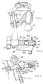
- FIG. 1 there is shown a camshaft 10 acting on a valve 18 against the force of the valve spring 20 by way of a train comprising a cam follower 12 and a rocker lever 14 pivotable about a fulcrum 16.
- the position of the fulcrum 16 is adjustable to vary the mechanical advantage of the lever and thereby adjust the maximum lift of the valve 18 even though the cam 10 has a fixed profile.
- the mechanism of the fulcrum 16 comprises two blocks 24 and 26 joined to one another by a pivot pin 28.
- the block 26 can slide along a track 22 while the block 24 can slide along the length of the roaker lever 14, which is also formed with a suitable track for guiding the block 24.
- the fulcrum mechanism prevents movement of the rocker lever 14 out of the plane of the drawing.
- the embodiment of the present invention illustrated in Figures 2 and 3 overcomes this problem and comprises two interacting levers 50 and 52 interposed between the camshaft 10′ and the valve 18′.
- the lever 50 is a fixed fulcrum lever pivotable about a shaft 54 and acted upon directly by the camshaft 10′.
- the lever 52 has two arms 52a and 52b which move in unison about a shaft 56.
- the lever arm 52a is disposed below the lever 50 and is moved by the latter through a coupling member 58 which is shown as being a pin.
- the resulting movement of the lever arm 52b causes the valve 18′ to be opened against the action of the valve spring (not shown).
- the mechanical advantage of the mechanism comprising the levers 50 and 52 depends upon the position of the coupling member 58.
- the coupling member 58 is mounted on a link arm 60 assembly formed of two plates straddling the coupling member 58 and pivotable about the axis of a pin 62 passing through an adjusting arm 64 projecting radially from the shaft 56 and mounted for rotation with the shaft 56.
- the adjusting arm 64 moves the position of the pin 62 which now moves the link arm 60 to reposition the coupling member 58 between the two levers 50 and 52a. The closer the coupling member 58 to the shaft 54, the less the lift of the valve 18′.
- the levers 50 and 52a will both rotate relative to the coupling member 58 during the opening of the valve and only line contact can be maintained.
- the coupling member has been shown as a pin rather than a flat block.
- line contact may cause severe wear and it is possible to substitute for the pin a two part block which incorporates a bearing surface, in a manner analogous to the block shown in Figure 1.
- valve springs 20 are relatively stiff and one or other of the springs of an engine is compressed at any angle of the camshaft 10. Thus if movement of all the coupling members 58 is effected simultaneously, then the force required must exceed the resistant of the valve springs. However, there are times when each coupling member associated with one of cylinder can be moved with minimal effort, namely when the valve is fully closed. To take advantage of this, one may stagger the movement of the individual coupling members so that each member 58 fulcrum is moved when it presents a minimum resistance.
- the coupling member 58 may be moved by way of a spring biased lost motion mechanism arranged between the adjusting arm 64 and the shaft 56.
- the spring in the lost motion mechanism is sufficiently strong to move the coupling member 58 when the valve is closed but not otherwise. If the coupling members 58 of all the cylinders are to be adjusted, then the shaft 56 is rotated to compress the springs of all the lost motion mechanisms. However, the individual link arms 60 will not move and displace their coupling members 58 until such time as the associated valve is closed and the coupling member 58 is not compressed between the two levers 50 and 52.
- the preferred embodiment of the invention can thus be seen to permit valve lift to be varied in an engine with an overhead camshaft arranged above the valves and to offer the additional advantage of enabling adjustment by a particularly simple and effective control system.
- the effort required for movement of the control system can be minimal this being important in order to avoid power losses.
Landscapes
- Engineering & Computer Science (AREA)
- Mechanical Engineering (AREA)
- General Engineering & Computer Science (AREA)
- Valve Device For Special Equipments (AREA)
Abstract
Claims (6)
- Mécanisme permettant d'atteindre une levée variable d'une soupape d'un moteur à combustion interne comprenant un arbre à cames à profil fixe, comprenant un système de leviers intercalé entre l'arbre à cames et la soupape, ce système de leviers comprenant un premier levier (50) à point d'articulation fixe sur lequel agit l'arbre (10′) à cames, un second levier (52) à point d'articulation fixe destiné à actionner une soupape (18′), et un élément d'accouplement (58) qui est mobile par rapport aux points d'articulation des deux leviers (50, 52), destiné à transmettre le mouvement du premier levier (50) au second levier (52),
caractérisé en ce que l'arbre (10′) à cames est un arbre à cames en tête, et en ce que l'élément d'accouplement (58) situé entre les leviers (50, 52) comporte un axe ou rouleau (58) qui est mobile sur la longueur de recouvrement des bras de levier (50, 52a). - Mécanisme selon la revendication 1, dans lequel chacun des deux leviers (50, 52) est construit sous forme d'un levier à bras unique.
- Mécanisme selon la revendication 1, dans lequel l'un ou les deux leviers (50, 52) est (sont) un (des) levier(s) à deux bras.
- Mécanisme selon l'une quelconque des revendications précédentes, dans lequel l'élément d'accouplement comporte un axe (58) porté par un levier supplémentaire (60) monté de façon pivotante sur l'extrémité extérieure d'un bras (64) saillant de l'arbre (56) sur lequel l'un des leviers est articulé.
- Mécanisme selon l'une quelconque des revendications précédentes, dans lequel un poussoir hydraulique est agencé entre le levier (52b) qui actionne la soupape et l'extrémité de la soupape (18′).
- Mécanisme selon la revendication 5, dans lequel la pression d'huile alimentant les poussoirs hydrauliques est transmise le long d'un arbre pivot (56) sur lequel sont montés les seconds leviers (52).
Applications Claiming Priority (2)
| Application Number | Priority Date | Filing Date | Title |
|---|---|---|---|
| GB8801425 | 1988-01-22 | ||
| GB8801425A GB2214570A (en) | 1988-01-22 | 1988-01-22 | Variable lift i.c. engine valves |
Publications (2)
| Publication Number | Publication Date |
|---|---|
| EP0397776A1 EP0397776A1 (fr) | 1990-11-22 |
| EP0397776B1 true EP0397776B1 (fr) | 1993-04-07 |
Family
ID=10630375
Family Applications (1)
| Application Number | Title | Priority Date | Filing Date |
|---|---|---|---|
| EP89902393A Expired - Lifetime EP0397776B1 (fr) | 1988-01-22 | 1989-01-20 | Mecanisme de soupapes a levee variable |
Country Status (4)
| Country | Link |
|---|---|
| US (1) | US5031584A (fr) |
| EP (1) | EP0397776B1 (fr) |
| GB (1) | GB2214570A (fr) |
| WO (1) | WO1989006742A1 (fr) |
Families Citing this family (6)
| Publication number | Priority date | Publication date | Assignee | Title |
|---|---|---|---|---|
| US5596960A (en) * | 1995-10-02 | 1997-01-28 | Ford Motor Company | Internal combustion engine |
| GB9703605D0 (en) * | 1997-02-21 | 1997-04-09 | T & N Technology Ltd | Operating mechanisms for valves |
| GB2323630B (en) * | 1997-03-26 | 2000-09-06 | T & N Technology Ltd | Operating mechanisms for valves |
| US5970932A (en) * | 1997-12-02 | 1999-10-26 | Panzer | Rocker arm assembly |
| US6189497B1 (en) | 1999-04-13 | 2001-02-20 | Gary L. Griffiths | Variable valve lift and timing camshaft support mechanism for internal combustion engines |
| DE10066056B4 (de) * | 2000-07-18 | 2006-02-02 | Thyssenkrupp Automotive Ag | Hubventilsteuerung für Kraftmaschinen |
Citations (2)
| Publication number | Priority date | Publication date | Assignee | Title |
|---|---|---|---|---|
| FR992780A (fr) * | 1948-08-24 | 1951-10-23 | Mécanisme de distribution par déclenchement dans les soupapes d'échappement des moteurs à quatre temps | |
| EP0280667A1 (fr) * | 1987-02-26 | 1988-08-31 | Ab Volvo | Mécanisme de soupapes pour moteur à combustion interne |
Family Cites Families (14)
| Publication number | Priority date | Publication date | Assignee | Title |
|---|---|---|---|---|
| GB682628A (en) * | 1949-07-20 | 1952-11-12 | Carl Friedrich Wilhelm Borgwar | Improvements in or relating to induction systems for internal combustion engines |
| US3422803A (en) * | 1967-06-07 | 1969-01-21 | Gen Motors Corp | Internal combustion engine construction and method for operation with lean air-fuel mixtures |
| US3413965A (en) * | 1967-07-13 | 1968-12-03 | Ford Motor Co | Mechanism for varying the operation of a reciprocating member |
| JPS55137305A (en) * | 1979-04-13 | 1980-10-27 | Nissan Motor Co Ltd | Valve lift for internal combustion engine |
| JPS6226562Y2 (fr) * | 1981-03-10 | 1987-07-08 | ||
| FR2519375B1 (fr) * | 1981-12-31 | 1986-07-11 | Baguena Michel | Distribution variable pour moteur a quatre temps |
| US4459946A (en) * | 1982-05-17 | 1984-07-17 | Investment Rarities, Incorporated | Valve actuating apparatus utilizing a multi-profiled cam unit for controlling internal combustion engines |
| JPS59168211A (ja) * | 1983-03-11 | 1984-09-21 | Honda Motor Co Ltd | 内燃機関用休止機能付動弁装置 |
| JPS59168212A (ja) * | 1983-03-11 | 1984-09-21 | Honda Motor Co Ltd | 内燃機関用弁作動制御装置 |
| JPS60228717A (ja) * | 1984-04-27 | 1985-11-14 | Suzuki Motor Co Ltd | 4サイクルエンジンのバルブリフト可変装置 |
| US4724822A (en) * | 1986-02-28 | 1988-02-16 | General Motors Corporation | Variable valve lift/timing mechanism |
| US4911124A (en) * | 1986-05-21 | 1990-03-27 | Bennett Automotive Technology Pty., Ltd. | Engines for use with gaseous fuels |
| US4699094A (en) * | 1986-05-27 | 1987-10-13 | General Motors Corporation | Rocker arm and hydraulic lash adjuster with load/motion control button |
| US4793307A (en) * | 1987-06-11 | 1988-12-27 | The Jacobs Manufacturing Company | Rocker arm decoupler for two-cycle engine retarder |
-
1988
- 1988-01-22 GB GB8801425A patent/GB2214570A/en not_active Withdrawn
-
1989
- 1989-01-20 EP EP89902393A patent/EP0397776B1/fr not_active Expired - Lifetime
- 1989-01-20 WO PCT/GB1989/000059 patent/WO1989006742A1/fr not_active Ceased
- 1989-01-20 US US07/548,897 patent/US5031584A/en not_active Expired - Fee Related
Patent Citations (2)
| Publication number | Priority date | Publication date | Assignee | Title |
|---|---|---|---|---|
| FR992780A (fr) * | 1948-08-24 | 1951-10-23 | Mécanisme de distribution par déclenchement dans les soupapes d'échappement des moteurs à quatre temps | |
| EP0280667A1 (fr) * | 1987-02-26 | 1988-08-31 | Ab Volvo | Mécanisme de soupapes pour moteur à combustion interne |
Also Published As
| Publication number | Publication date |
|---|---|
| WO1989006742A1 (fr) | 1989-07-27 |
| GB2214570A (en) | 1989-09-06 |
| EP0397776A1 (fr) | 1990-11-22 |
| GB8801425D0 (en) | 1988-02-24 |
| US5031584A (en) | 1991-07-16 |
Similar Documents
| Publication | Publication Date | Title |
|---|---|---|
| US5592906A (en) | Method and device for variable valve control of an internal combustion engine | |
| US7624711B2 (en) | Variable mechanical valve control for an internal combustion engine | |
| US6907852B2 (en) | Valve operating device for variable stroke adjustment of a charge exchange valve of an internal combustion engine | |
| US5373818A (en) | Valve gear assembly for an internal-combustion engine | |
| US7814875B2 (en) | Stroke adjusting device for valves of a combustion engine | |
| US5119773A (en) | Apparatus for operating the valves on internal combustion engines with a variable valve lift curve | |
| US7469669B2 (en) | Variable valve train mechanism of internal combustion engine | |
| US4791893A (en) | Valve train arrangement for multi-valve engine | |
| WO1996016253A1 (fr) | Mecanisme de levee variable de soupapes pour moteur a combustion interne | |
| JPH05306607A (ja) | 内燃機関の動弁装置 | |
| US5431132A (en) | Variable valve gear of internal combustion engines | |
| EP0601570B1 (fr) | Commande de soupape pour moteur à combustion interne | |
| US7096835B2 (en) | Valve train device for an engine | |
| US5016581A (en) | Valve mechanisms | |
| US7069890B2 (en) | Valve train device for an engine | |
| EP0397776B1 (fr) | Mecanisme de soupapes a levee variable | |
| US7225773B2 (en) | Variable stroke valve drive for an internal combustion engine | |
| EP0434331A1 (fr) | Dispositif d'entraînement de soupapes pour moteur à combustion interne | |
| US4495902A (en) | Mechanism for variably controlling an internal combustion engine valve | |
| US7367298B2 (en) | Variable valve gear for internal combustion engine | |
| WO2005017324A1 (fr) | Commande de soupapes variable | |
| SU1574872A1 (ru) | Механизм газораспределени двигател внутреннего сгорани с регулируемыми фазами | |
| JP2893748B2 (ja) | エンジンの弁作動装置 | |
| JPH02221612A (ja) | 内燃機関の可変動弁装置 | |
| WO2004088096A1 (fr) | Appareil destine a un moteur a combustion interne |
Legal Events
| Date | Code | Title | Description |
|---|---|---|---|
| PUAI | Public reference made under article 153(3) epc to a published international application that has entered the european phase |
Free format text: ORIGINAL CODE: 0009012 |
|
| 17P | Request for examination filed |
Effective date: 19900424 |
|
| AK | Designated contracting states |
Kind code of ref document: A1 Designated state(s): DE FR GB |
|
| 17Q | First examination report despatched |
Effective date: 19920124 |
|
| GRAA | (expected) grant |
Free format text: ORIGINAL CODE: 0009210 |
|
| AK | Designated contracting states |
Kind code of ref document: B1 Designated state(s): DE FR GB |
|
| ET | Fr: translation filed | ||
| REF | Corresponds to: |
Ref document number: 68905922 Country of ref document: DE Date of ref document: 19930513 |
|
| PLBE | No opposition filed within time limit |
Free format text: ORIGINAL CODE: 0009261 |
|
| STAA | Information on the status of an ep patent application or granted ep patent |
Free format text: STATUS: NO OPPOSITION FILED WITHIN TIME LIMIT |
|
| 26N | No opposition filed | ||
| PGFP | Annual fee paid to national office [announced via postgrant information from national office to epo] |
Ref country code: FR Payment date: 19980113 Year of fee payment: 10 |
|
| PGFP | Annual fee paid to national office [announced via postgrant information from national office to epo] |
Ref country code: GB Payment date: 19981223 Year of fee payment: 11 |
|
| PGFP | Annual fee paid to national office [announced via postgrant information from national office to epo] |
Ref country code: DE Payment date: 19990129 Year of fee payment: 11 |
|
| PG25 | Lapsed in a contracting state [announced via postgrant information from national office to epo] |
Ref country code: FR Free format text: LAPSE BECAUSE OF NON-PAYMENT OF DUE FEES Effective date: 19990930 |
|
| REG | Reference to a national code |
Ref country code: FR Ref legal event code: ST |
|
| PG25 | Lapsed in a contracting state [announced via postgrant information from national office to epo] |
Ref country code: GB Free format text: LAPSE BECAUSE OF NON-PAYMENT OF DUE FEES Effective date: 20000120 |
|
| GBPC | Gb: european patent ceased through non-payment of renewal fee |
Effective date: 20000120 |
|
| PG25 | Lapsed in a contracting state [announced via postgrant information from national office to epo] |
Ref country code: DE Free format text: LAPSE BECAUSE OF NON-PAYMENT OF DUE FEES Effective date: 20001101 |