EP0397979A2 - Vulkanisierplatte - Google Patents
Vulkanisierplatte Download PDFInfo
- Publication number
- EP0397979A2 EP0397979A2 EP90104587A EP90104587A EP0397979A2 EP 0397979 A2 EP0397979 A2 EP 0397979A2 EP 90104587 A EP90104587 A EP 90104587A EP 90104587 A EP90104587 A EP 90104587A EP 0397979 A2 EP0397979 A2 EP 0397979A2
- Authority
- EP
- European Patent Office
- Prior art keywords
- plate
- vulcanizing
- parts
- plate according
- cooling
- Prior art date
- Legal status (The legal status is an assumption and is not a legal conclusion. Google has not performed a legal analysis and makes no representation as to the accuracy of the status listed.)
- Granted
Links
- 238000004073 vulcanization Methods 0.000 title 1
- 238000001816 cooling Methods 0.000 claims abstract description 30
- 238000010438 heat treatment Methods 0.000 claims abstract description 17
- 239000002826 coolant Substances 0.000 claims description 5
- 239000007788 liquid Substances 0.000 claims description 3
- 229910000906 Bronze Inorganic materials 0.000 claims description 2
- 229910000990 Ni alloy Inorganic materials 0.000 claims 1
- XLYOFNOQVPJJNP-UHFFFAOYSA-N water Substances O XLYOFNOQVPJJNP-UHFFFAOYSA-N 0.000 description 4
- 239000002184 metal Substances 0.000 description 3
- 229910052751 metal Inorganic materials 0.000 description 3
- 230000001133 acceleration Effects 0.000 description 1
- 229910045601 alloy Inorganic materials 0.000 description 1
- 239000000956 alloy Substances 0.000 description 1
- 238000009434 installation Methods 0.000 description 1
- 238000004519 manufacturing process Methods 0.000 description 1
- 239000000463 material Substances 0.000 description 1
- 150000002739 metals Chemical class 0.000 description 1
- 230000000717 retained effect Effects 0.000 description 1
Images


Classifications
-
- B—PERFORMING OPERATIONS; TRANSPORTING
- B30—PRESSES
- B30B—PRESSES IN GENERAL
- B30B15/00—Details of, or accessories for, presses; Auxiliary measures in connection with pressing
- B30B15/06—Platens or press rams
- B30B15/062—Press plates
- B30B15/064—Press plates with heating or cooling means
-
- B—PERFORMING OPERATIONS; TRANSPORTING
- B29—WORKING OF PLASTICS; WORKING OF SUBSTANCES IN A PLASTIC STATE IN GENERAL
- B29C—SHAPING OR JOINING OF PLASTICS; SHAPING OF MATERIAL IN A PLASTIC STATE, NOT OTHERWISE PROVIDED FOR; AFTER-TREATMENT OF THE SHAPED PRODUCTS, e.g. REPAIRING
- B29C33/00—Moulds or cores; Details thereof or accessories therefor
- B29C33/02—Moulds or cores; Details thereof or accessories therefor with incorporated heating or cooling means
- B29C33/04—Moulds or cores; Details thereof or accessories therefor with incorporated heating or cooling means using liquids, gas or steam
-
- B—PERFORMING OPERATIONS; TRANSPORTING
- B29—WORKING OF PLASTICS; WORKING OF SUBSTANCES IN A PLASTIC STATE IN GENERAL
- B29L—INDEXING SCHEME ASSOCIATED WITH SUBCLASS B29C, RELATING TO PARTICULAR ARTICLES
- B29L2031/00—Other particular articles
- B29L2031/709—Articles shaped in a closed loop, e.g. conveyor belts
- B29L2031/7092—Conveyor belts
Definitions
- the invention relates to a vulcanizing plate for use in a device for the thermal connection of at least two parts, in particular conveyor belt ends, the vulcanizing plate being provided with a heating area facing the medium to be vulcanized in the position of use and a cooling area used for recooling.
- Vulcanizing plates are known in different designs.
- the invention is based on a vulcanizing plate as described in DE-AS 27 27 300 by the applicant.
- DE-OS 22 48 810 shows a somewhat different structure with a panel radiator, clamped between two plates.
- the object of the invention is to provide a solution with which vulcanizing plates are maintained in a satisfactory manner of functioning while at the same time considerably reducing the weight when the plates are transported to and from the place of use.
- a single plate can be disassembled into two part plates for transport, which automatically brings about a considerable reduction in the weight of the parts that have to be moved by people, for example underground.
- Optimal designs of both the heating plate and the cooling plate can be retained, the design can be improved even further according to the solutions known here.
- the plate parts are equipped with elements on the outer edge for positive and / or non-positive connection of the plate parts to one another are.
- This can be, for example, tongue and groove connections, dovetail guides, screw connections, quick release devices or the like.
- each plate part is provided with individual carrying handles, a particularly expedient design being provided when the carrying handles can be pivoted from a position for transporting the plate into a working position, as is the case with the invention Design also provides.
- the carrying handles can be lowered in the working position of the heating plate in order to expose the terminal strips on the end face, the handling handles of the cooling plate can be inserted, for example, into the interior before assembly.
- the cooling plate part is formed from two separate layers for the individual application of a gaseous or a liquid coolant.
- a gaseous or a liquid coolant For example, fresh air can be used as coolant underground, water as coolant or both media at the same time as coolant, which inevitably leads to an acceleration of the cooling behavior.
- the plate parts are formed from a bronze alloy, in particular from a (Cu Al 10 Ni) alloy.
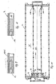
- the vulcanizing plate generally designated 1, consists of a cooling plate part 2, which is embedded in a form-fitting manner in a heating plate part 3 in the position of use and can be removed and transported separately from this part.
- these are equipped with end-side, outer edge-side locking elements 4 and 5, which are designed as tongue and groove blocks.
- These blocks 4 and 5 serve simultaneously as a bearing for at least one of the carrying handles 6 and 7 of the heating plate part on the one hand and the cooling plate part on the other hand, wherein the carrying handle 7 'of the cooling plate part can be pushed together into the interior of this plate part before assembly, as shown in FIG 1 was shown in dashed lines.
- the insertability is indicated there by the double arrow 8.
- Fig. 3 an end view of the heating plate 1 is shown, wherein the mobility of the handle 6 is indicated by the double arrows 9. A height adjustment of the bearing and locking blocks 4 is indicated there by an arrow 10. The height adjustability can be useful if the straps are put on and are to be wedged laterally, the blocks 4 can then serve as a stop for corresponding wedging aids.
- the plug connection for the electrical supply line of the heating plate 3 is only indicated in FIG. 3 and designated by 11.
- the cooling plate itself has a two-layer design and can be acted upon by two different cooling media, be it simultaneously, in succession or separately from one another.
- the air supply and water supply nozzles are indicated in Fig. 1 and denoted by 12 and 13, depending on their particular configuration not according to the invention.
- the cooling plate 2 is described in more detail below.
- FIG. 4 to 8 show the installation situations in the area of the carrying handles of the two plate parts and the height adjustability of the outer bearing block (FIG. 6) with the aid of an adjusting screw, which is otherwise not shown in the figures.
- the blocks 4 and 5 can be seen hooking through the engagement of a T-shaped element 18 in block 5 of one plate in a corresponding groove 19 in block 4 of the other plate, as can be clearly seen in FIG. 8.
- other configurations can also be selected, for example a dovetail guide or the like.
- FIG 9 shows a partial top view of the cut cooling plate 2, which is designed for air cooling, with an air inlet connector 12, a central air guide duct 20 and outer air return ducts 21 with an air outlet connector 22, the corresponding section through the air inlet connector 12 in FIG 10 shown.
- FIG. 12 shows the area of the cooling plate 2 which is used for water cooling.
- two water inlet nozzles 13 are provided on the outer edge with flow channels 23 and an inner return channel 24 um to achieve the counterflow principle compared to air cooling.
- the cooling channels can also be flowed through in the opposite direction.
- 9 shows the area of an inlet connector 13 or a corresponding outlet connector through the layer structure of the cooling plate 2.
- the shaft connectors 25 (FIG. 7) of the carrying handles 6 can be hollow-cylindrical in order to enable adjacent plates to be screwed through these hollow cylinders, but they can also be provided with threads in an alternating order To be able to screw in threaded bolts u. Like. more.
Landscapes
- Engineering & Computer Science (AREA)
- Mechanical Engineering (AREA)
- Heating, Cooling, Or Curing Plastics Or The Like In General (AREA)
- Lining Or Joining Of Plastics Or The Like (AREA)
- Moulds For Moulding Plastics Or The Like (AREA)
- Lock And Its Accessories (AREA)
- Organic Insulating Materials (AREA)
Abstract
Description
- Die Erfindung richtet sich auf eine Vulkanisierplatte zum Einsatz in einer Vorrichtung zum thermischen Verbinden von mindestens zwei Teilen, insbesondere von Fördergurtenden, wobei die Vulkanisierplatte mit einem in der Gebrauchslage dem zu vulkanisierenden Medium zugewandten Heizbereich und einem zur Rückkühlung eingesetzten Kühlbereich versehen ist.
- Vulkanisierplatten sind in unterschiedlichen Ausführungen bekannt. So geht die Erfindung von einer Vulkanisierplatte aus, wie sie in der DE-AS 27 27 300 der Anmelderin beschrieben ist. Einen etwas anderen Aufbau mit einem Flächenheizkörper, eingespannt zwischen zwei Platten, zeigt beispielsweise die DE-OS 22 48 810.
- Bekannte Vulkanisierplatten sind vergleichsweise ausgereift und führen zu guten Ergebnissen, sie haben allerdings den Nachteil, daß sie vergleichsweise schwer sind, was ihre Handhabung nicht vereinfacht. Um das Gewicht zu verringern ist die Anmelderin bereits einen anderen Weg gegangen, der in der WO 87/06876 beschrieben ist, wobei Kühl- und Heizkanäle in Leichtmetallprofilleisten im wesentlichen parallel nebeneinander vorgesehen sind. Derartige Leichtmetall-Lösungen lassen sich nicht immer in der Praxis einsetzen. So ist der Einsatz derartiger Platten unter Tage unerwünscht bzw. verboten.
- Aufgabe der Erfindung ist die Schaffung einer Lösung, mit der Vulkanisierplatten in zufriedenstellender Funktionsweise beibehalten werden unter gleichzeitiger erheblicher Gewichtsreduzierung beim Transport der Platten zum Einsatzort hin und von dort wieder weg.
- Diese Aufgabe wird mit einer erfindungsgemäßen Vulkanisierplatte der eingangs bezeichneten Art dadurch gelöst, daß der Heizbereich und der Kühlbereich von körperlich voneinander trennbaren, in der Gebrauchslage zusammengefügten Plattenteilen gebildet sind.
- Mit der Erfindung wird erreicht, daß eine Einzelplatte in zwei Teilplatten für den Transport zerlegbar ist, womit automatisch eine erhebliche Gewichtsreduzierung der Teile bewirkt wird, die von den Personen beispielsweise unter Tage bewegt werden müssen. Dabei können optimale Gestaltungen sowohl der Heizplatte als auch der Kühlplatte beibehalten werden, die Gestaltung kann nach den hier bekannten Lösungen noch verbessert werden.
- In Ausgestaltung ist vorgesehen, daß die Plattenteile mit außenrandseitigen Elementen zum form- und/oder kraftschlüssigen Verbinden der Plattenteile aneinander ausgerüstet sind. Hierbei kann es sich beispielsweise um Nut/Federverbindungen, um Schwalbenschwanzführungen, um Verschraubungen, um Schnellspanneinrichtungen od. dgl. handeln.
- Um die Handhabbarkeit weiter zu verbessern ist vorgesehen, daß jeder Plattenteil mit individuellen Traggriffen versehen ist, wobei hier eine besonders zweckmäßige Gestaltung dann gegeben ist, wenn die Traggriffe aus einer Lage zum Transport der Platte in eine Arbeitslage verschwenkbar sind, wie dies die Erfindung in weiterer Ausgestaltung ebenfalls vorsieht. Dabei können die Traggriffe in der Arbeitslage der Heizplatte nach unten abgesenkt werden, um die stirnseitigen Anschlußleisten freizugeben, die Handhabungsgriffe der Kühlplatte können beispielsweise in das Innere vor der Montage eingeschoben werden.
- Um die Kühlleistung des Kühlplattenteiles zu erhöhen, kann vorgesehen sei, daß das Kühlplattenteil aus zwei voneinander getrennten Schichten zur individuellen Beaufschlagung mit einem gasförmigen bzw. einem flüssigen Kühlmittel gebildet ist. So kann beispielsweise unter Tage Frischluft als Kühlmittel, Wasser als Kühlmittel oder beide Medien gleichzeitig als Kühlmittel eingesetzt werden, was zwangsläufig zu einer Beschleunigung des Abkühlverhaltens führt.
- Weitere Ausgestaltungen bestehen darin, daß die Verrastelemente der Plattenteile als stirnseitige Nut/Federblöcke ausgebildet sind, wobei die Nut/Federblöcke gleichzeitig die Lagerelemente für die Handgriffe bilden können.
- Zweckmäßig ist, wenn wenigstens je ein außenrandseitiger Block in seiner Höhe verstellbar an dem Heizplattenteil angeordnet ist, was bei der späteren Zwischenlage der zu vulkanisierenden Gurtbänder, deren Positionierung und Verteilung an den jeweiligen Vulkanisierplattenpaaren erleichtert. Durch die starke Gewichtseinsparung auch gegenüber Leichtmetallen können auch schwerere Werkstoffe bei der Herstellung der Heizplatten eingesetzt werden. In einer für die Erfindung besonders wesentlichen Ausgestaltung ist daher vorgesehen, daß die Plattenteile aus einer Bronzelegierung, insbesondere aus einer (Cu Al 10 Ni)-Legierung, gebildet sind.
- Weitere Merkmale, Einzelheiten und Vorteile der Erfindung ergeben sich aus der nachfolgenden Beschreibung sowie anhand der Zeichnung. Diese zeigt in
- Fig. 1 eine Aufsicht auf eine Heizplatte nach der Erfindung,
- Fig. 2 eine Seitenansicht einer Heizplatte,
- Fig. 3 eine räumliche Darstellung eines Ausschnittes der Platte im stirnseitigen Steckerbereich,
- Fig. 4 bis 8 Detailzeichnungen der Griffsituation der beiden Plattenteile in der Montagesituation, wobei die römischen Schnittlinienangaben den entsprechenden Zeichnungen entsprechen. Dabei stellt
- Fig. 5 die Schnittlinie V-V in Fig. 8 dar,
- Fig. 6 den Schnitt etwa gemäß VI-VI in Fig. 7 und
- Fig. 7 den Schnitt gemäß VII-VII in Fig. 4,
- Fig. 9 einen Schnitt gemäß Linie IX-IX in Fig. 11,
- Fig. 10 einen Schnitt gemäß Linie X-X ebenfalls Fig. 11,
- Fig. 11 eine Aufsicht auf einen Horizontalschnitt durch die gasbeaufschlagte Kühlebene und
- Fig. 12 einen Schnitt durch die flüssigkeitsbeaufschlagte Kühlebene der Kühlplatte.
- Die allgemein mit 1 bezeichnete Vulkanisierplatte besteht aus einem Kühlplattenteil 2, der formschlüssig in einem Heizplattenteil 3 in der Gebrauchslage eingebettet ist und aus diesem Teil ausnehmbar und getrennt transportierbar ist. Zur formschlüssigen Verbindung der beiden Plattentei le 2 und 3 aneinander sind diese mit stirnseitigen, außenrandseitigen Rastelementen 4 bzw. 5 ausgerüstet, die als Nut/Federblöcke ausgebildet sind. Diese Blöcke 4 und 5 dienen gleichzeitig als Lager für wenigstens einen der Traggriffe 6 bzw. 7 des Heizplattenteiles einerseits bzw. des Kühlplattenteiles andererseits, wobei der Traggriff 7′ des Kühlplattenteiles in das Innere dieses Plattenteiles vor der Montage zusammen einschiebbar ist, wie dies in Fig. 1 gestrichelt wiedergegeben wurde. Die Einschiebbarkeit ist dort mit dem Doppelpfeil 8 angedeutet.
- In Fig. 3 ist eine stirnseitige Ansicht der Heizplatte 1 dargestellt, wobei die Bewegbarkeit des Traggriffes 6 durch die Doppelpfeile 9 angedeutet ist. Eine Höhenverstellbarkeit der Lager- und Rastblöcke 4 ist dort mit einem Pfeil 10 angedeutet. Die Höhenverstellbarkeit kann dann sinnvoll sein, wenn die Gurtbänder aufgelegt sind und seitlich verkeilt werden sollen, die Blöcke 4 können dann als Anschlag für entsprechende Verkeilungshilfsmittel dienen. Der Steckeranschluß für die elektrische Zuleitung der Heizplatte 3 ist in Fig. 3 lediglich angedeutet und mit 11 bezeichnet. Die Kühlplatte selbst ist im dargestellten Beispiel zweilagig ausgebildet und von zwei unterschiedlichen Kühlmedien beaufschlagbar, sei es gleichzeitig, nacheinander oder getrennt voneinander. Die Luftzufuhr- und Wasserzufuhrstutzen sind in Fig. 1 angedeutet und mit 12 bzw. 13 bezeichnet, auf deren spezielle Ausgestaltung kommt es nach der Erfindung nicht an. Die Kühlplatte 2 ist weiter unten noch näher beschrieben.
- Die Fig. 4 bis 8 zeigen die Einbausituationen im Bereich der Traggriffe der beiden Plattenteile und die Höhenverstellbarkeit des äußeren Lagerblockes (Fig. 6) mit Hilfe einer Einstellschraube, die ansonsten in den Figuren nicht näher dargestellt ist. Erkennbar verhaken die Blöcke 4 und 5 durch den eingriff eines T-förmigen Elementes 18 im Block 5 der einen Platte in eine entsprechende Nut 19 im Block 4 der anderen Platte, wie sich dies deutlich aus Fig. 8 ergibt. Neben dieser T-förmigen Gestaltung von Eingriffselement und Nut können auch andere Konfigurationen gewählt werden, etwa eine Schwalbenschwanzführung od. dgl.
- Die Fig. 9 zeigt eine Teilaufsicht auf die geschnittene Kühlplatte 2 in der Lage, die für die Luftkühlung ausgebildet ist, mit einem Lufteintrittsstutzen 12, einem mittleren Luftführungskanal 20 und äußeren Luftrückführkanälen 21 mit Luftaustrittsstutzen 22, der entsprechende Schnitt durch den Lufteintrittsstutzen 12 ist in Fig. 10 dargestellt.
- In Fig. 12 ist der Bereich der Kühlplatte 2 dargestellt, der zur Wasserkühlung dient. Hier sind beispielsweise zwei Wassereintrittsstutzen 13 außenrandseitig vorgesehen mit Strömungskanälen 23 und einem inneren Rückführkanal 24, um das Gegenstromprinzip gegenüber der Luftkühlung zu erreichen. Natürlich können die Kühlkanäle auch in umgekehrter Richtung durchströmt sein. Der Schnitt gemäß Fig. 9 zeigt den Bereich eines Eintrittsstutzens 13 bzw. eines entsprechenden Austrittsstutzens durch den Schichtaufbau der Kühlplatte 2.
- Um beispielsweise benachbarte Platten aneinander festlegen zu können, können die Wellenstutzen 25 (Fig. 7) der Traggriffe 6 hohlzylindrisch ausgebildet sein, um eine Verschraubung benachbarter Platten durch diese Hohlzylinder hindurch zu ermöglichen, sie können aber auch in wechselnder Folge mit Gewinde versehen sein, um Gewindebolzen einschrauben zu können u. dgl. mehr.
Claims (9)
dadurch gekennzeichnet,
daß der Heizbereich und der Kühlbereich von körperlich voneinander trennbaren, in der Gebrauchslage zusammengefügten Plattenteilen (2,3) gebildet sind.
dadurch gekennzeichnet,
daß die Plattenteile (2,3) mit außenrandseitigen Elementen (4,5) zum form- und/oder kraftschlüssigen Verbinden der Plattenteile aneinander ausgerüstet sind.
dadurch gekennzeichnet,
daß jeder Plattenteil (4,5) mit individuellen Traggriffen (6,7) versehen ist.
dadurch gekennzeichnet,
daß die Traggriffe (6,7) aus einer Lage zum Transport der Platte (1) in eine Arbeitslage verschwenkbar sind.
dadurch gekennzeichnet,
daß das Kühlplattenteil (2) aus zwei voneinander getrennten Schichten zur individuellen Beaufschlagung mit einem gasförmigen bzw. einem flüssigen Kühlmittel gebildet ist.
dadurch gekennzeichnet,
daß die Verrastelemente der Plattenteile als stirnseitige Nut/Federblöcke (4,5) ausgebildet sind.
dadurch gekennzeichnet,
daß die Nut/Federblöcke (4,5) Lagerelemente für die Handgriffe (6,7) bilden.
dadurch gekennzeichnet,
daß wenigstens je ein außenrandseitiger Block (4) in seiner Höhe verstellbar an dem Heizplattenteil (3) angeordnet ist.
dadurch gekennzeichnet,
daß die Plattenteile (2,3) aus einer Bronzelegierung, insbesondere aus einer Cu Al 10 Ni-Legierung, gebildet sind.
Priority Applications (1)
| Application Number | Priority Date | Filing Date | Title |
|---|---|---|---|
| AT90104587T ATE99592T1 (de) | 1989-05-18 | 1990-03-10 | Vulkanisierplatte. |
Applications Claiming Priority (2)
| Application Number | Priority Date | Filing Date | Title |
|---|---|---|---|
| DE3916163A DE3916163A1 (de) | 1989-05-18 | 1989-05-18 | Vulkanisierplatte |
| DE3916163 | 1989-05-18 |
Publications (3)
| Publication Number | Publication Date |
|---|---|
| EP0397979A2 true EP0397979A2 (de) | 1990-11-22 |
| EP0397979A3 EP0397979A3 (de) | 1991-07-31 |
| EP0397979B1 EP0397979B1 (de) | 1994-01-05 |
Family
ID=6380870
Family Applications (1)
| Application Number | Title | Priority Date | Filing Date |
|---|---|---|---|
| EP90104587A Expired - Lifetime EP0397979B1 (de) | 1989-05-18 | 1990-03-10 | Vulkanisierplatte |
Country Status (4)
| Country | Link |
|---|---|
| EP (1) | EP0397979B1 (de) |
| AT (1) | ATE99592T1 (de) |
| DE (2) | DE3916163A1 (de) |
| ES (1) | ES2047732T3 (de) |
Cited By (1)
| Publication number | Priority date | Publication date | Assignee | Title |
|---|---|---|---|---|
| WO2007009762A3 (de) * | 2005-07-20 | 2007-04-26 | Backhaus Monika | Werkzeug zum verpressen eines multilayerpresspaketes, insbesondere zur anordnung in einer presse bzw. paketaufbau zum verpressen von multilayern bzw. presse zur verpressung bzw. herstellung von multilayern |
Family Cites Families (3)
| Publication number | Priority date | Publication date | Assignee | Title |
|---|---|---|---|---|
| US3594867A (en) * | 1967-10-28 | 1971-07-27 | Dieffenbacher Gmbh Maschf | Heating platen press |
| US3754499A (en) * | 1971-09-27 | 1973-08-28 | North American Rockwell | High temperature platens |
| DE2948084C2 (de) * | 1979-11-29 | 1983-03-17 | F.E. Schulte Strathaus Kg, 4750 Unna | Vorrichtung zum thermischen Verbinden von mindestens zwei Teilen, insbesondere von Fördergurtenden |
-
1989
- 1989-05-18 DE DE3916163A patent/DE3916163A1/de not_active Withdrawn
-
1990
- 1990-03-10 ES ES90104587T patent/ES2047732T3/es not_active Expired - Lifetime
- 1990-03-10 AT AT90104587T patent/ATE99592T1/de not_active IP Right Cessation
- 1990-03-10 DE DE90104587T patent/DE59004085D1/de not_active Expired - Fee Related
- 1990-03-10 EP EP90104587A patent/EP0397979B1/de not_active Expired - Lifetime
Cited By (2)
| Publication number | Priority date | Publication date | Assignee | Title |
|---|---|---|---|---|
| WO2007009762A3 (de) * | 2005-07-20 | 2007-04-26 | Backhaus Monika | Werkzeug zum verpressen eines multilayerpresspaketes, insbesondere zur anordnung in einer presse bzw. paketaufbau zum verpressen von multilayern bzw. presse zur verpressung bzw. herstellung von multilayern |
| US7832448B2 (en) | 2005-07-20 | 2010-11-16 | Wickeder Westfalenstahl Gmbh | Mold for pressing a multilayer press stack, in particular for arrangement in a press and/or stack structure for pressing multilayer composites and/or a press for pressing and/or producing multilayer composites |
Also Published As
| Publication number | Publication date |
|---|---|
| EP0397979B1 (de) | 1994-01-05 |
| ATE99592T1 (de) | 1994-01-15 |
| ES2047732T3 (es) | 1994-03-01 |
| DE3916163A1 (de) | 1990-11-22 |
| DE59004085D1 (de) | 1994-02-17 |
| EP0397979A3 (de) | 1991-07-31 |
Similar Documents
| Publication | Publication Date | Title |
|---|---|---|
| DE3238284C2 (de) | Strangpreßkopf zum Herstellen von Flachprofilen aus verschiedenen Gummi- oder Kunststoffmischungen | |
| DE69725925T2 (de) | Linearwälzlagereinheit, die eine Abdichtungsstruktur trägt | |
| EP0226711A2 (de) | Schneefräse | |
| EP0724486B1 (de) | Sprühblock eines sprühwerkzeugs | |
| DE2843504C2 (de) | ||
| DE10257931A1 (de) | Dichtung | |
| DE2309121C3 (de) | Oberflächenkühler für einen von Luft umströmten Körper | |
| DE2633173C2 (de) | Druckmittelführungsskanal, insbesondere an einem Abbauförderer einer Kohlegewinnungseinrichtung | |
| DE69705765T2 (de) | Vorrichtung zum Einstellen der Düsenlippen beim Strangpressen | |
| DE3119265C2 (de) | Vorrichtung zum Zuführen einer vorbestimmten Anzahl von Kolbenringen | |
| DE2927233C2 (de) | ||
| EP0397979A2 (de) | Vulkanisierplatte | |
| DE3713837C2 (de) | ||
| DE3043346A1 (de) | Progressiver pneumatischer anlasser und schaltung fuer seinen betrieb | |
| DE69403399T2 (de) | Elektrisches Verbindungssystem | |
| DE102019105980B4 (de) | Umkehrsammler für ein Kühlsystem einer Traktionsbatterie eines elektrisch betriebenen Fahrzeugs und Kühlsystem für eine Traktionsbatterie | |
| DE3604963A1 (de) | Einsatz zum unterteilen einer giessform | |
| EP0558777B1 (de) | Faltenbalg für Übergangseinrichtungen von Eisenbahnwagen | |
| DE3602642A1 (de) | Hubeinrichtung fuer einen hublader mit einem an einer kette haengenden schlitten | |
| DE2511584C3 (de) | Stecksystem zum Aufbau von Gehäuserahmen | |
| DE3115396C1 (de) | Pressenplatte, insbesondere für Vorrichtungen zur Reparatur und zum Endlosmachen von Fördergurten | |
| DE2048357A1 (de) | Stranggießkokille | |
| DE19807873C2 (de) | Fluidverteilervorrichtung | |
| DE2200526A1 (de) | Gittervorrichtung | |
| WO1990002695A1 (de) | Konstruktionsprofil |
Legal Events
| Date | Code | Title | Description |
|---|---|---|---|
| PUAI | Public reference made under article 153(3) epc to a published international application that has entered the european phase |
Free format text: ORIGINAL CODE: 0009012 |
|
| AK | Designated contracting states |
Kind code of ref document: A2 Designated state(s): AT BE CH DE DK ES FR GB GR IT LI LU NL SE |
|
| PUAL | Search report despatched |
Free format text: ORIGINAL CODE: 0009013 |
|
| AK | Designated contracting states |
Kind code of ref document: A3 Designated state(s): AT BE CH DE DK ES FR GB GR IT LI LU NL SE |
|
| 17P | Request for examination filed |
Effective date: 19910718 |
|
| 17Q | First examination report despatched |
Effective date: 19921216 |
|
| GRAA | (expected) grant |
Free format text: ORIGINAL CODE: 0009210 |
|
| AK | Designated contracting states |
Kind code of ref document: B1 Designated state(s): AT BE CH DE DK ES FR GB GR IT LI LU NL SE |
|
| PG25 | Lapsed in a contracting state [announced via postgrant information from national office to epo] |
Ref country code: IT Free format text: LAPSE BECAUSE OF FAILURE TO SUBMIT A TRANSLATION OF THE DESCRIPTION OR TO PAY THE FEE WITHIN THE PRE;WARNING: LAPSES OF ITALIAN PATENTS WITH EFFECTIVE DATE BEFORE 2007 MAY HAVE OCCURRED AT ANY TIME BEFORE 2007. THE CORRECT EFFECTIVE DATE MAY BE DIFFERENT FROM THE ONE RECORDED.SCRIBED TIME-LIMIT Effective date: 19940105 Ref country code: SE Effective date: 19940105 Ref country code: NL Effective date: 19940105 Ref country code: DK Effective date: 19940105 Ref country code: GR Free format text: LAPSE BECAUSE OF FAILURE TO SUBMIT A TRANSLATION OF THE DESCRIPTION OR TO PAY THE FEE WITHIN THE PRESCRIBED TIME-LIMIT Effective date: 19940105 |
|
| REF | Corresponds to: |
Ref document number: 99592 Country of ref document: AT Date of ref document: 19940115 Kind code of ref document: T |
|
| REF | Corresponds to: |
Ref document number: 59004085 Country of ref document: DE Date of ref document: 19940217 |
|
| REG | Reference to a national code |
Ref country code: ES Ref legal event code: FG2A Ref document number: 2047732 Country of ref document: ES Kind code of ref document: T3 |
|
| PG25 | Lapsed in a contracting state [announced via postgrant information from national office to epo] |
Ref country code: AT Effective date: 19940310 |
|
| GBT | Gb: translation of ep patent filed (gb section 77(6)(a)/1977) |
Effective date: 19940217 |
|
| PG25 | Lapsed in a contracting state [announced via postgrant information from national office to epo] |
Ref country code: LU Free format text: LAPSE BECAUSE OF NON-PAYMENT OF DUE FEES Effective date: 19940331 Ref country code: CH Effective date: 19940331 Ref country code: LI Effective date: 19940331 |
|
| ET | Fr: translation filed | ||
| NLV1 | Nl: lapsed or annulled due to failure to fulfill the requirements of art. 29p and 29m of the patents act | ||
| PLBE | No opposition filed within time limit |
Free format text: ORIGINAL CODE: 0009261 |
|
| STAA | Information on the status of an ep patent application or granted ep patent |
Free format text: STATUS: NO OPPOSITION FILED WITHIN TIME LIMIT |
|
| REG | Reference to a national code |
Ref country code: CH Ref legal event code: PL |
|
| 26N | No opposition filed | ||
| PGFP | Annual fee paid to national office [announced via postgrant information from national office to epo] |
Ref country code: FR Payment date: 19970214 Year of fee payment: 8 |
|
| PGFP | Annual fee paid to national office [announced via postgrant information from national office to epo] |
Ref country code: GB Payment date: 19970224 Year of fee payment: 8 |
|
| PGFP | Annual fee paid to national office [announced via postgrant information from national office to epo] |
Ref country code: BE Payment date: 19970304 Year of fee payment: 8 |
|
| PGFP | Annual fee paid to national office [announced via postgrant information from national office to epo] |
Ref country code: ES Payment date: 19970306 Year of fee payment: 8 |
|
| PG25 | Lapsed in a contracting state [announced via postgrant information from national office to epo] |
Ref country code: GB Free format text: LAPSE BECAUSE OF NON-PAYMENT OF DUE FEES Effective date: 19980310 |
|
| PG25 | Lapsed in a contracting state [announced via postgrant information from national office to epo] |
Ref country code: ES Free format text: LAPSE BECAUSE OF EXPIRATION OF PROTECTION Effective date: 19980311 |
|
| PG25 | Lapsed in a contracting state [announced via postgrant information from national office to epo] |
Ref country code: FR Free format text: THE PATENT HAS BEEN ANNULLED BY A DECISION OF A NATIONAL AUTHORITY Effective date: 19980331 Ref country code: BE Free format text: LAPSE BECAUSE OF NON-PAYMENT OF DUE FEES Effective date: 19980331 |
|
| BERE | Be: lapsed |
Owner name: F.E. SCHULTE STRATHAUS K.G. Effective date: 19980331 |
|
| GBPC | Gb: european patent ceased through non-payment of renewal fee |
Effective date: 19980310 |
|
| REG | Reference to a national code |
Ref country code: FR Ref legal event code: ST |
|
| PGFP | Annual fee paid to national office [announced via postgrant information from national office to epo] |
Ref country code: DE Payment date: 19990227 Year of fee payment: 10 |
|
| REG | Reference to a national code |
Ref country code: ES Ref legal event code: FD2A Effective date: 20000201 |
|
| PG25 | Lapsed in a contracting state [announced via postgrant information from national office to epo] |
Ref country code: DE Free format text: LAPSE BECAUSE OF NON-PAYMENT OF DUE FEES Effective date: 20010103 |