EP0397996A2 - Moteur à combustion interne - Google Patents
Moteur à combustion interne Download PDFInfo
- Publication number
- EP0397996A2 EP0397996A2 EP90105549A EP90105549A EP0397996A2 EP 0397996 A2 EP0397996 A2 EP 0397996A2 EP 90105549 A EP90105549 A EP 90105549A EP 90105549 A EP90105549 A EP 90105549A EP 0397996 A2 EP0397996 A2 EP 0397996A2
- Authority
- EP
- European Patent Office
- Prior art keywords
- gas chamber
- gate plate
- gas
- guide
- chamber
- Prior art date
- Legal status (The legal status is an assumption and is not a legal conclusion. Google has not performed a legal analysis and makes no representation as to the accuracy of the status listed.)
- Withdrawn
Links
Images




















































































































Classifications
-
- F—MECHANICAL ENGINEERING; LIGHTING; HEATING; WEAPONS; BLASTING
- F01—MACHINES OR ENGINES IN GENERAL; ENGINE PLANTS IN GENERAL; STEAM ENGINES
- F01C—ROTARY-PISTON OR OSCILLATING-PISTON MACHINES OR ENGINES
- F01C21/00—Component parts, details or accessories not provided for in groups F01C1/00 - F01C20/00
- F01C21/18—Arrangements for admission or discharge of the working fluid, e.g. constructional features of the inlet or outlet
-
- F—MECHANICAL ENGINEERING; LIGHTING; HEATING; WEAPONS; BLASTING
- F01—MACHINES OR ENGINES IN GENERAL; ENGINE PLANTS IN GENERAL; STEAM ENGINES
- F01C—ROTARY-PISTON OR OSCILLATING-PISTON MACHINES OR ENGINES
- F01C1/00—Rotary-piston machines or engines
- F01C1/30—Rotary-piston machines or engines having the characteristics covered by two or more groups F01C1/02, F01C1/08, F01C1/22, F01C1/24 or having the characteristics covered by one of these groups together with some other type of movement between co-operating members
- F01C1/34—Rotary-piston machines or engines having the characteristics covered by two or more groups F01C1/02, F01C1/08, F01C1/22, F01C1/24 or having the characteristics covered by one of these groups together with some other type of movement between co-operating members having the movement defined in group F01C1/08 or F01C1/22 and relative reciprocation between the co-operating members
- F01C1/344—Rotary-piston machines or engines having the characteristics covered by two or more groups F01C1/02, F01C1/08, F01C1/22, F01C1/24 or having the characteristics covered by one of these groups together with some other type of movement between co-operating members having the movement defined in group F01C1/08 or F01C1/22 and relative reciprocation between the co-operating members with vanes reciprocating with respect to the inner member
- F01C1/3446—Rotary-piston machines or engines having the characteristics covered by two or more groups F01C1/02, F01C1/08, F01C1/22, F01C1/24 or having the characteristics covered by one of these groups together with some other type of movement between co-operating members having the movement defined in group F01C1/08 or F01C1/22 and relative reciprocation between the co-operating members with vanes reciprocating with respect to the inner member the inner and outer member being in contact along more than one line or surface
-
- F—MECHANICAL ENGINEERING; LIGHTING; HEATING; WEAPONS; BLASTING
- F01—MACHINES OR ENGINES IN GENERAL; ENGINE PLANTS IN GENERAL; STEAM ENGINES
- F01C—ROTARY-PISTON OR OSCILLATING-PISTON MACHINES OR ENGINES
- F01C1/00—Rotary-piston machines or engines
- F01C1/30—Rotary-piston machines or engines having the characteristics covered by two or more groups F01C1/02, F01C1/08, F01C1/22, F01C1/24 or having the characteristics covered by one of these groups together with some other type of movement between co-operating members
- F01C1/34—Rotary-piston machines or engines having the characteristics covered by two or more groups F01C1/02, F01C1/08, F01C1/22, F01C1/24 or having the characteristics covered by one of these groups together with some other type of movement between co-operating members having the movement defined in group F01C1/08 or F01C1/22 and relative reciprocation between the co-operating members
- F01C1/356—Rotary-piston machines or engines having the characteristics covered by two or more groups F01C1/02, F01C1/08, F01C1/22, F01C1/24 or having the characteristics covered by one of these groups together with some other type of movement between co-operating members having the movement defined in group F01C1/08 or F01C1/22 and relative reciprocation between the co-operating members with vanes reciprocating with respect to the outer member
- F01C1/3566—Rotary-piston machines or engines having the characteristics covered by two or more groups F01C1/02, F01C1/08, F01C1/22, F01C1/24 or having the characteristics covered by one of these groups together with some other type of movement between co-operating members having the movement defined in group F01C1/08 or F01C1/22 and relative reciprocation between the co-operating members with vanes reciprocating with respect to the outer member the inner and outer member being in contact along more than one line or surface
-
- F—MECHANICAL ENGINEERING; LIGHTING; HEATING; WEAPONS; BLASTING
- F01—MACHINES OR ENGINES IN GENERAL; ENGINE PLANTS IN GENERAL; STEAM ENGINES
- F01C—ROTARY-PISTON OR OSCILLATING-PISTON MACHINES OR ENGINES
- F01C1/00—Rotary-piston machines or engines
- F01C1/30—Rotary-piston machines or engines having the characteristics covered by two or more groups F01C1/02, F01C1/08, F01C1/22, F01C1/24 or having the characteristics covered by one of these groups together with some other type of movement between co-operating members
- F01C1/34—Rotary-piston machines or engines having the characteristics covered by two or more groups F01C1/02, F01C1/08, F01C1/22, F01C1/24 or having the characteristics covered by one of these groups together with some other type of movement between co-operating members having the movement defined in group F01C1/08 or F01C1/22 and relative reciprocation between the co-operating members
- F01C1/356—Rotary-piston machines or engines having the characteristics covered by two or more groups F01C1/02, F01C1/08, F01C1/22, F01C1/24 or having the characteristics covered by one of these groups together with some other type of movement between co-operating members having the movement defined in group F01C1/08 or F01C1/22 and relative reciprocation between the co-operating members with vanes reciprocating with respect to the outer member
- F01C1/3568—Rotary-piston machines or engines having the characteristics covered by two or more groups F01C1/02, F01C1/08, F01C1/22, F01C1/24 or having the characteristics covered by one of these groups together with some other type of movement between co-operating members having the movement defined in group F01C1/08 or F01C1/22 and relative reciprocation between the co-operating members with vanes reciprocating with respect to the outer member with axially movable vanes
-
- F—MECHANICAL ENGINEERING; LIGHTING; HEATING; WEAPONS; BLASTING
- F01—MACHINES OR ENGINES IN GENERAL; ENGINE PLANTS IN GENERAL; STEAM ENGINES
- F01C—ROTARY-PISTON OR OSCILLATING-PISTON MACHINES OR ENGINES
- F01C11/00—Combinations of two or more machines or engines, each being of rotary-piston or oscillating-piston type
- F01C11/002—Combinations of two or more machines or engines, each being of rotary-piston or oscillating-piston type of similar working principle
- F01C11/004—Combinations of two or more machines or engines, each being of rotary-piston or oscillating-piston type of similar working principle and of complementary function, e.g. internal combustion engine with supercharger
-
- F—MECHANICAL ENGINEERING; LIGHTING; HEATING; WEAPONS; BLASTING
- F01—MACHINES OR ENGINES IN GENERAL; ENGINE PLANTS IN GENERAL; STEAM ENGINES
- F01C—ROTARY-PISTON OR OSCILLATING-PISTON MACHINES OR ENGINES
- F01C21/00—Component parts, details or accessories not provided for in groups F01C1/00 - F01C20/00
- F01C21/06—Heating; Cooling; Heat insulation
-
- F—MECHANICAL ENGINEERING; LIGHTING; HEATING; WEAPONS; BLASTING
- F01—MACHINES OR ENGINES IN GENERAL; ENGINE PLANTS IN GENERAL; STEAM ENGINES
- F01C—ROTARY-PISTON OR OSCILLATING-PISTON MACHINES OR ENGINES
- F01C21/00—Component parts, details or accessories not provided for in groups F01C1/00 - F01C20/00
- F01C21/08—Rotary pistons
- F01C21/0809—Construction of vanes or vane holders
-
- F—MECHANICAL ENGINEERING; LIGHTING; HEATING; WEAPONS; BLASTING
- F02—COMBUSTION ENGINES; HOT-GAS OR COMBUSTION-PRODUCT ENGINE PLANTS
- F02B—INTERNAL-COMBUSTION PISTON ENGINES; COMBUSTION ENGINES IN GENERAL
- F02B53/00—Internal-combustion aspects of rotary-piston or oscillating-piston engines
-
- F—MECHANICAL ENGINEERING; LIGHTING; HEATING; WEAPONS; BLASTING
- F02—COMBUSTION ENGINES; HOT-GAS OR COMBUSTION-PRODUCT ENGINE PLANTS
- F02B—INTERNAL-COMBUSTION PISTON ENGINES; COMBUSTION ENGINES IN GENERAL
- F02B55/00—Internal-combustion aspects of rotary pistons; Outer members for co-operation with rotary pistons
- F02B55/08—Outer members for co-operation with rotary pistons; Casings
- F02B55/10—Cooling thereof
- F02B55/12—Cooling thereof by air or other gas
-
- F—MECHANICAL ENGINEERING; LIGHTING; HEATING; WEAPONS; BLASTING
- F02—COMBUSTION ENGINES; HOT-GAS OR COMBUSTION-PRODUCT ENGINE PLANTS
- F02B—INTERNAL-COMBUSTION PISTON ENGINES; COMBUSTION ENGINES IN GENERAL
- F02B75/00—Other engines
- F02B75/02—Engines characterised by their cycles, e.g. six-stroke
- F02B2075/022—Engines characterised by their cycles, e.g. six-stroke having less than six strokes per cycle
- F02B2075/027—Engines characterised by their cycles, e.g. six-stroke having less than six strokes per cycle four
-
- Y—GENERAL TAGGING OF NEW TECHNOLOGICAL DEVELOPMENTS; GENERAL TAGGING OF CROSS-SECTIONAL TECHNOLOGIES SPANNING OVER SEVERAL SECTIONS OF THE IPC; TECHNICAL SUBJECTS COVERED BY FORMER USPC CROSS-REFERENCE ART COLLECTIONS [XRACs] AND DIGESTS
- Y02—TECHNOLOGIES OR APPLICATIONS FOR MITIGATION OR ADAPTATION AGAINST CLIMATE CHANGE
- Y02T—CLIMATE CHANGE MITIGATION TECHNOLOGIES RELATED TO TRANSPORTATION
- Y02T10/00—Road transport of goods or passengers
- Y02T10/10—Internal combustion engine [ICE] based vehicles
- Y02T10/12—Improving ICE efficiencies
Definitions
- the invention relates to internal combustion engines.
- An object of the invention is to provide an improved internal combustion engine of high efficiency, giving lower pollution and less vibration than conventional engines.
- the invention is applicable to internal combustion engines of various kinds.
- a-1 is the structure which intake compressive gas chamber Cx and explosive exhaust gas chamber Cy are placed in the same body, due to it possesses obliquely stridding over exchange pressure-saved gas chamber structure of b-1, b-2, b-3, b-4, b-6, b-7 in Item B, therefore, it is characterized in that:
- valve port 55 is blockaded and can not communicates two sections of gas chamber, and as to the function of guiding gas, fixed valve rings 51, 52 are fixed, and rotor 31 is in rotary action, valve port 55 and coaxial valve port 49 are connected and communicated instantly in action, therefore, it is doubted whether it can completely guide through fuel gas, as shown in Fig. 2, if sliding abutment 65 and projection 43 press and push gas, due to the cross section of ports 49, 55 is too small, therefore, the efficiency of transmitting fuel gas is greatly lowered down when fuel is required to be transmitted quickly.
- valve port 55 Another key point is the distribution of groove, due to the limitation of valve port 55, there only discloses circumferential internal rotor motion , the middle fixed valve rings 51, 52 assemble three valve port 55 in ring, and rotor 31 of two sides assemble three projections 43, 43a with same arc angle to form cylinder, there is no disclosure of disk, external rotor and linear design.
- valve port completely separate from gas chambers 40, 40a, and it does not possess function of saving pressure and returning combustion of waste gas, due to time of guiding gas and the area of cross section of valve port corresponding to guide hole is too small, therefore, under quick rotation, there is phenomenon of incomplete burning or cancelling out of efficiency.
- valve port 55 As to 360° of this case, due to the distance between valve port 55 and each projection 43 or 43a of gas chambers 40, 40a, it will cause loss of angle which can not produce dynamic power, the main reason is that valve port 55 is placed transversely and let projections 43, 43a must avoid away.
- This case is also three-sectional independent structure which is combined in series, wherein at two side sections of rotors 1, 2, each of them possesses separated gas chambers 7, 8 and vanes 28, 29, middle section part is partitioned by fixed central wall 11, and has function of guiding gas, the action of guiding gas will transversely communicate when gas chambers 7, 8 at two sides are overlapped, the arc occupied by inlet port 42 and transfer port 43 which are formed by gas chambers 7, 8 is very large, therefore arc angle which produces dynamic power will be reduced, and as shown in Fig. 3 it is the starting point of dynamic stroke.
- Transfer port formed by overlapping gas chambers 7, 8 separates from explosive exhaust gas chamber before ignition, therefore, waste gas and pressure after explosion can not be stored for raising pressure and returning combustion in next cycle.
- Exchange gas chamber of this case is communicated by three transfer ports 43, 43', 43''' on the middle fixed central wall 11 when overlapped parts of gas groove of two sides rotate and crisscross, therefore, the I "I rotary tangent direction of tramsfer ports 43, 43 , 43 which is verical to rotors 1, 2, when its explosive action is produced, it must let above overlapped part completely leave transfer ports 43, 43', 43 , two sections respectively possess three gas groove, gas groove of each corresponding set are placed in overlapping head and tail parts for guiding gas, this kind of structure is similar to case 2,583,633, by guessing, working angle is lost in order to obtain wider transmission angle is the main reason to be granted a patent, but this case can only arrange gas chambers 7, 8 in internal type, and it has no design of external rotor or linear type.
- transfer port 43 does not possess function of saving pressure and returning combustion of waste gas, therefore, also it can not prepress on gas chamber 8.
- Exchange gas chamber of this case is to use outer shell 1 as guide passage, oval rotor 20 continuously presses and sends fuel gas into 7, and when another oval rotor 21 rotates to Fig. 20, fuel gas is sent from 7 to 8, and store in the cylinder until tip of rotor 20 passes through 7, end of rotor 21 is to ignite and explode, before explosion, of course, it start valve 9, the overlapped part of working gas chamber formed by two sectional rotors 20, 21 of this design is very large, therefore, placement of valve 9 is necessary, due to the limitation of rotor shape, therefore, the formed gas chamber must be outside outer shell, therefore, there is no design of external rotor and disk type, it is impossible to be arranged in linear type.
- Character of this case is to assemble intake valve in the middle fixed ring, said valve is driven by the divided cam on main axle, front section 7 of transmission fuel gas port of this structure isolates rear section 8 and explosive exhaust gas chamber 3 from valve 9, the front end of rear section 8 and exhaust port is about 135°, and rotor contacts inner wall of stator by point, before exhaust, 3 does not separate 8, and can not be stored in the inner port, after explosion, waste gas and pressure are stored in 3, for raising pressure and returning combustion in next cycle, its arc of pressure intake is very large, therefore, its working angle is reduced, there have no design of linear and disk type driving structure and desing of external rotor.
- Case of G.B. Patent NOS. 1,531,541 and 197,811 are similar to cases of German Patent NOS. 1,814,899 and 2,847,890, they relates directly to assemble valve housings 22, 23 and ports 24, 25 and gas chamber 21 of the same circumference at outer sheel 21 of column type rotor 10, from the sequence of action shown in Figs. 9a to 9i, 10a to 10i, 11 a to 11 i, 12a to 12i, the gas guide method is to guide gas through transmission pipe outside main body, in exhaust, C.C.B. and exhaust port communicate each other (as shown in Figs. 10c and 12c), after explosion, waste gas and pressure can not be stored in C.C.B. for raising pressure and returning combustion in next cycle.
- Combustion Chamber 50 communicates groove 13 by port 52, in action, fuel gas in groove 13 is continuously transmitted into combustion chamber 50 from port 51, as shown in Figs. 9a to 9i then fuel gas is stored in groove 14 with bigger volume, when combustion chamber 50 will not press and transmit fuel gas into groove 14, and then ignition system 70 in combustion chamber 50 immediately ignites and explodes, as shown in figures, groove 14 can stride over exhaust port and combustion chamber 50, and between grooves 13, 14, there possesses a certain arc degree and does not possess gas groove, as shown in Figs. 1a to 1d, in other words, working angles between grooves 13, 14 are less than 180°.
- combustion chamber 5 In Figs. 26, 27 of case 1,814,899, there possesses rectangular combustion chamber 5"", said combustion chamber 5 must match distance between grooves 3"", 4"", and let its width can simultaneously connect 3"", 4"", and direction of combustion chamber 5 is vertical to the tangent motion direction of rotor 2"".
- each 360° is only born and pushed by groove 14, at the interval between grooves 13, 14, there places C.C.B. 50, and it cause the working angle occupied by C.C.B. to be lessened.
- Character of b-5 is that: guide groove or guide transverse groove of exchange gas chamber possesses turbulent flow structure of tur-ulent column, barrier, hole, granule, curved passage.
- Character of b-8 is that: it possess structure with function of releasing pressure.
- Character of Item E is that: it possesses dynamic unit which is constituted by multi-sectional gas chamber Cx and single-set gas chamber Cy of e-3, and dynamic unit which is constituted by multi-row gas chamber Cx and single-row gas chamber Cy, and gas chamber set Cx, Cy of e-6 possesses guide transverse groove.
- Character of Item F is that: combined type gate plate set of f-2 and bottom of gate plate of f-3 possess inclined crack structure, f-4 possesses lubricant groove structure, at front and rear end of trace of gate plate set Gx of f-5, there are turbulent gate GM, cross sectional structure of gate plate of f-6, guide hole structure of f-7.
- Character of Item H is that: h-5 is linear driving internal combustion engine.
- Character of Item I is that: i-2 is gate plate motion osmotic type lubricant structure.
- Character of Item J is that: rotor of j-1 possesses turbine vane circulative cooling structure, and j-2 possesses rodiating vane open type cooling structure.
- Character of Item L is that: it possesses each ring-shaped and side coupling interface device and synchronously distributive interface device.
- the present invention relates to a design of an internal combustion engine which improves pollution of engine and its main body is exchange pressure-saved gas chamber.
- rotary type, linear type and reciprocating type embodiments are obtained by selecting structure of main body of engine and varying the structures of exchange pressure-saved gas chamber, gas chamber and gate plate, working angle of engine are enlarged by selecting exchange pressure-saved gas chamber and lowering down pollution because of separation of gas chamber and two times intake help combustion, and it can reduce vibration through rotary engine of right circular rotor and provide linear drive and reciprocating type separate gas chamber
- this design compares with conventional reciprocating engine: it possesses many merits more than the conventional reciprocating engine, for example, the conventional four-stroke internal combustion engine possesses low pollution, but its explosive stroke of real output work is only 1/4 of working angle, and although the working angle of two-stroke engine possesses about 1/2 cycle working angle, but its drawback is that there co-exists a section of intake and exhaust during the stroke, it will cause incomplete combustion and pollution, owing to the function of
- Above design possesses two sets of separate gas chamber which are respectively used for produce functions of two procedures in the four procedures of intake, compression, explosion, exhaust of OTTO cycle, these two sets of separate gas chamber are constituted by cylinder, exterior arc, ring inner wall, disk surface or conic surface or concave surface or linear coupled surface gas chamber, or they are constituted by double gas chamber formed by double-side piston, or two sets of gas chamber in which two sets of piston are lir'ked.
- This design mainly includes: rotary or linear internal combustion engine which can drive in one-way or two-way and is constituted by active body with common use gate plate set and passive body with separate gas chamber connected in series, and rotary or linear internal combustion engine with function of saving pressure and returning combustion of waste gas are combined by exchange gas chamber set with obliquely stridden or inclined guide groove and function of saving pressure and passive body with cross separate gas chamber or reciprocating internal combusiton engine with exchange pressure-saved gas chamber and separate gas chamber are constituted by double-side piston or double piston ocnnected in series, and exchange valve.
- Passive body with serial connection gas chamber it possesses at least a set of unequal depth, equal length or unequal length gas chamber sets Cy, Cx to connect in series along driving trace to form gas chamber sets Cx, Cy; wherein gas chamber Cx is shallower, gas chamber Cy is deeper, the sectional shapes of both of them along motion direction are same, and can closely joint with common gate plate GC, the largest depth of gas chamber Cx is used for its gate plate GC to slide into, and let one-way intake valve on GC completely face toward the gas in gas chamber Cx which will be compressed, in the meantime, transmission guide hole is still hidden and sealed in the gate plate sliding seat, the leading end of gas chamber Cy possesses a largest depth for gate plate GC to slide down, and transmission guide hole will completely expose in order to guide high pressure gas saved in the pressure-saved gas chamber of gate body into explosive exhaust gas chamber Cy, at the leading end of gas chamber Cy, there assembled a transverse crack for placing plug, or fuel nozzle, the deepest part of gas chamber section stridden by guide transverse
- Plug or fuel nozzle it is assembled at the lagging end of common use gate plate set GC on active body which is used as fixing body and coupled with common gas chamber CC or guide transverse groove and can avoid the concave structure which is interfered by common use gas chamber.
- INTAKE PORT Groove or hole is placed on the active body or passive body which is used as fixing body, or groove or hole is placed on the active body or passive body which is used as motion body and leads to the supplying tube of fuel or help-combustion gas.
- EXHAUST PORT Groove or hole is placed on the active body or passive body which is used as fixing body, or groove or hole is placed on the active body or passive body which is used as motion body and leads to the exhaust pipe of waste gas.
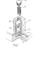
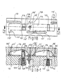
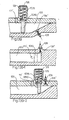
- This kind of structural method of rotary and linear type engine is the main characteristic of common gate plate serial connection gas chamber type and is combined by connecting in series with different depth gas chamber sets Cy, Cx along driving trace, and Cx, Cy are the structures of common use gate plates GC, GC as shown in Fig. 1 and Fig. 1-1, and its character is the section facing to the surface of motion is square shape or arc shape having wave or labyrinth type, at the lower side of gate plate facing to the surface of motion, there are one-way intake valve 101,101 to let fuel gas enter into, and its inner part possesses a pressure-saved gas chamber 102, at the upper part of lagging surface, there is a transmission guide hole 103 as shown in Fig.
- gas chamber Cx 104 is shallower, gas chamber Cy 105 is deeper , their sectional shapes along direction of motion are same and can closely joint with common gate plate GC 106, the largest depth of gas chamber Cx 104 is used for common gate plate GC 106 to slide into and can make one-way intake valve 101 of GC 106 completely face to the gas of gas chamber Cx 104 which will be compressed, and compress the gas and store it in the pressure-saved gas chamber 102, in the meantime, transmission guide hole 103 is still hidden in the gate plate sliding seat 107, and the leading end of gas chamber Cy possesses a larger depth for gate plate GC 106 to slide down, and transmission guide hole 103 completely expose out to guide high pressure gas stored in the pressure-saved gas chamber of gate body into explosive exhaust gas chamber Cy 105, and at the leading end of Cy, there assembled a guide transverse groove 105' for placing plug 108 or fuel nozzle 109 for keeping the deepest part of gas chamber section stridden by
- Transmission guide hole 103 is under the status of hiding in the gate plate seat 107, and gas chamber Cy 105 passes through the deepest section and from the deep to the shallow to let common gate plate GC 106 be hidden into gate plate seat again, to seal high pressure gas stored in the pressure-saved gas chamber 102 after combustion, and its hiding point is between points of explosion and exhaust.
- Outlet end of transmission guide hole 103 of common use gate plate GC 106 further assemble pneumatic seal ring for reducing the loss of leaking gas at low speed.
- the serial connection method of above gas chambers Cx and Cy can be the serial connection of single-set gas chamber Cx and Cy or serial connection of multi-set gas chamber Cx and single-set gas chamber Cy.
- common gate plate type internal combustion engine with exchange gas chamber and separate gas chamber includes the following designs
- This independent gate plate type internal combustion engine with ezchange gas chamber and separate gas chamber includes design of each item as follows:
- Fixed body possesses ecchange gas chamber CZ 1060 and intake compressive gate plate set Gx 1040, gate plate set Gx 1040, at the lagging side of gate plate set Gx 1040, there designed intake port 110' and explosive exhaust gate Gy 1050 which is coupled with Gx 1040 on the different trace, at the leading side of Gy 1050, there designed exhaust port 111', at above-mentioned exchange gas chamber CZ 1060,, there designed plug 108 or fuel nozzle 109 or both of them.
- Intake compressive chamber 104 is designed at motion body and coupled with Gx 1040 on active body and explosive exhaust gas chamber Cy 105 is designed on the motion body to couple with Gy 1050 on active body.
- this design is applied on the embodiment of rotary type engine, if structure which possesses gate plate seats 1074, 1075 and gate plate set Gx 1040, Gy 1050 is used as fixed body and structure which possesses gas chamber set Cx 104, Cy 105 is used as internal rotor motion body, on the fixed body, there designed common gate plate set, and gate plate seats 1074, 1075 and intake compressive gate plate set Gx 1040, and explosive exhaust gate plate set Gy 1050, and exchange gas chamber CZ 1060, on the coupling surface of motion body and fixed body, there designed intake compressive gas chamber Cx 104 and explosive exhaust gas chamber Cy 105 which are connected in parallel and coupled with gate plate set Gx 1040, Gy 1050 on fixed body.
- Plug 108 or fuel nozzle 109 is placed on exchange gas chamber CZ 1060 or placed in the concave chamber which is coupled with guide transverse groove 105' when working angle is ignited, or placed at the leading end of motion body gas chamber Cy 105 and can avoid to be interferred by gate plate set Gy 1050 in the concave chamber or guide transverse groove 105'.
- intake port 110' and exhaust port 111' are placed at the passive body, then intake port 110' is placed at the leading end of gas chamber Cx 104 and penetrate through gas chamber Cx 104 in order to guide through gas chamber Cx 104 and transmission pipe of fuel gas exhaust port 111' is placed at the lagging end of gas chamber Cy 105 and can avoid to be interferred by explosive exhaust gate plate set Gy 1050 and penetrate through gas chamber 105 in order to guide through gas chamber Cy 105 and transmission pipe of waste gas.
- intake port 110' and exhaust port 111' are placed at the active body, this intake port 110' is assembled at the lagging end of gate plate set Gx 1040 and on the trace which is coupled with gas chamber Cx, this exhaust port 111' is assembled at the leading end of explosive exhaust gate plate set Gy 105 and on the trace which is coupled with gas chamber Cy in motion, the working procedure of this embodiment is shown in Figs. 35 to 35-5.
- Fig. 36 is a graphic view of the external rotary type embodiment of above structure, as shown in figure, fixed body with gate plate seats 1074, 1075 and gate plate set Gx 1040 and Gy 1050 is cup or ring type structure,and possesses parallel connected gas chambers Cx 104, Cy 105 which are coupled on it in ring in order to accept drive; the relationship of intake port 110', exhaust port 111', plug 108 or fuel nozzle 109, gas chamber set Cx 104, Cy 105, gate plate set Gx 1040 and Gy 1050 is as same as Figs. 34 and 35. 2. As shown in Figs.
- intake port 110' is assembled on the fixed rail of gate plate set Gx 1040, Gy 1050, and at the leading end of gate plate set Gy 1050, there designed exhaust port 111' which is coupled with gas chamber Cy 105 in driving in order to exhaust waste gas of gas chamber Cy 105, at the lagging end of intake compressive gate plate set Gx 1040, there designed intake port 110' which is coupled with gas chamber Cx 104 in driving in order to let fresh fuel gas enter into, the working procedure of above embodiment is shown in Figs. 37-2 to 37-7; and fuel supplying system and exhaust system also can be assembled on the motion body, and as shown in Figs.
- rotary type engine which designs active body as motion body and passive body as fixed body, active body which possesses gate plate seats 1074, 1075, and intake compressive gate plate set Gx 1040 and explosive exhaust gate plate set Gy 1050 and exchange gas chamber set CZ 1060 is used as internal rotor motion body, and passive body which possesses intake compressive gas chamber set Cx 104 and explosive exhaust gas chamber set Cy 105 is used as fixed body, on the coupling surface of fixed body and motion body, there designed intake compressive gas chamber Cx 104 and explosive exhaust gas chamber Cy 105 which are connected in parallel and coupled with gate plate set Gx 1040, Gy 1050 on motion body.
- plug 108 or fuel nozzle 109 is assembled on the concave structure 105" which is at the leading end of gas chamber Cy 105 of fixed body and can avoid to be interferred by explosive exhaust gate plate set Gy 105, or assembled in the exchange gas chamber CZ 1060 on motion body; if intake port 110' and exhaust port 111' are assembled on the motion body, and then at the lagging end of gate plate Gx 1040, there designed an intake port 110 which communicats gas chamber Cx 104 of fixed body Cx 104 for guide through gas chamber Cx 104 and intake duct in rotation in order to let fresh fuel gas enter into, at the leading end of gate plate Gy 1050, there designed an exhaust port 111' which communicates gas chamber Cy 105 of fixed body to transmit gas of above gas chamber Cy 105 to exhaust duct in rotation and exhaust waste gas of Cy.
- intake port 110' and exhaust port 111' are assembled on the passive body which is used as fixed body, and intake port is placed at the leading end of gas chamber Cx 104 and can avoid to be interferred by common gate plate set Gx 1040 and penetrate through gas chamber Cx 104 to guide through gas chamber Cx 104 and fuel gas transmission duct; exhaust port 111' is placed at the lagging end of gas chamber Cy 105 and can avoid to be interferred by gate plate set Gy 1050 and penetrate through gas chamber Cy 105 to guide through gas chamber Cy 105 and transmission duct of waste gas.
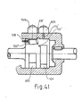
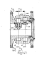
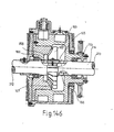
- Fig. 41 is an external rotor structural embodiment in which active body is acted as motion body, and passive body is acted as fixed body, and the relationship of intake port 110', exhaust port 111 plug 108 or fuel nozzle 109, and gas chamber Cx 104, Cy 105, gate plate set Gx 1040, Cy 1050 is as same as Fig.
- intake port is designed on the passive body which is used as fixed body, and its placement is that intake port is placed at the leading end of gas chamber Cx 104 and can avoid to be interferred by gate plate Gx 1040 and penetrate thorugh gas chamber Cx 104 to guide through gas chamber Cx 104 and transmission duct of fuel gas; exhaust port 111' is placed at the lagging end of gas chamber Cy 105 and can avoid to be interferred by gate plate set Gy 1050 and penetrate through gas chamber Cy 105 in order to guide through gas chamber Cy 105 and transmission pipe of waste gas.
- intake port 110' and exhaust port 111' are placed on the active body which is used as external rotor,and guide grooves 112 and 113 and intake exhaust duct are coupled by guide hole on side wall which is at same side or at different side or guide hole on outer circumference o of motion body in order to couple with the fixed transmission interface of inatke exhaust duct, this kind of transmission interface will be described there in after.
- intake port 110' and exhaust port 111' are assembled on the motion body, and at the leading end of explosive exhaust gate plate set Gy 1050, there designed exhaust port 111' which is coupled by gas chamber Cy 105 in driving in order to exhaust waste gas of Cx 105; at the lagging end of intake compressive gate plate set Gx 1040, there designed intake port 110' which is coupled by gas chamber set Cx in driving in order to let fresh fuel gas enter into.
- the working procedure of this method is shown in Figs.42-1 to 42-6.
- Structure of intake compressive gas chamber Cx and explosive exhaust gas chamber Cy are placed at different body, is that Intake compressive gas chamber Cx 104 and explosive exhaust gas chamber Cy 105 are placed in different body, this design is to use the structure which possesses explosive exhaust gate plate set Gy 1050 and intake compressive gas chamber Cx 104 as active body, and structure which possesses intake compressive gate plate set Gx 1040 and explosive exhaust gas chamber Cy 105 is used as passive body.
- the relative position of intake compressive gas chamber set Cx 104 and explosive exhaust gas chamber set Cy 105 of this internal combustion engine is respectively assembled on the corresponding coupling surface of fixed body andmot motion body.
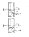
- Figs. 43 and 43-1 to 43-2 it is a rotary type embodiment, on the passive body which is used as motion body, there designed explosive exhaust gas chamber set Cy 105 and intake compressive gate Gx 1040; and on the active body which is used as fixed body, there designed explosive exhaust gate Gy 1050, intake compressive gas chamber Cx 104, and intake port z, exhaust port 111
- Motion body possesses gas chamber set Cy 105 and gate plate driving seat 107, on the rotary trace of intake compressive gas chamber Cx 104 corresponding to fixed body, there is gate plate Gx 1040 extending out of intake compressive gas chamber Cx 104 which closely sticks against inear ring of stator, at the leading end of gas chamber Cx 104, there designed intake port 110', this intake port 110' is placed at the position which can avoid to be interferred by gate plate Gx 1040 for guiding through gas chamber set Cx 104 and intake duct; exhaust port 111' is placed at the leading end of gate plate set Gy 1050 on the fixed body and coupled with gas chamber set Cy 105 on motion body; plug 108 or fuel nozzle 109 for ignition and combustion is independently placed in the concave structure 105" on the trace of gas chamber Cy 105 which is placed at the lagging end of gate plate set Gy 1050 on active body and corresponds to rotor, or placed in the concave chamber 105" which is placed at the leading end of gas chamber set Cy 105 on the passive
- exchanging gas The function of exchanging gas is that a guide groove 104' which is placed at the lagging end of intake eompressive gas chamber Cx 104 of fixed body near side of gas chamber Cy 105 turning back to the leading end and guide transverse groove 105' which is assembled on the explosive exhaust gas chamber Cy 105 of motion body and extends to gas chamber set Cx 104 are communicated each other in order to transmit fuel gas when rotary phase is overlapped, and on the lagging trace of guide groove of active body turning back to gas chamber set Cx 104, there further assembled a pressure-saved gas chamber CP 1060' which intersects guide transverse groove 105' of gas chamber set Cy 105 and gas chamber Cy 105 after ignition and combusiton, and is separated from guide transverse groove 105' before exhaust of this cycle in' order to save high pressure fuel gas of this cycle and mix with fresh fuel gas in the next cycle for promoting pressure of fresh fuel gas to be ignited and burned, its working precedure is shown in Figs. 43-3 to 43-6,
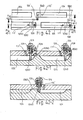
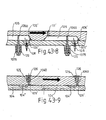
- Figs 43-7 to 43-9 is a graphic view of linear type embodiment
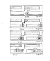
- Figs. 43-10 to 43-13 is a diagram of working procedure.
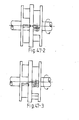
- 44 to 44-1 also it can be constituted by guide transverse groove 104 which is placed at the lagging end of Cx 104 near side of gas chamber set Cy 105 and guide transverse groove 104 which is placed at the leading end of Cy 105 near side of gas chamber set Cx 104, length of two sets guide transverse groove 104 and 105' is suitable for communicating and overlapping each other in the range of working angle of exchange gas in driving and transmitting fuel gas, the working angle of exchange gas is set by the width of two sets of guide transverse groove 104' and 105'; or guide transverse groove which is placed in the gas chamber Cy 105 near gas chamber Cx 104 is bent and turned to the leading end, the bent part can be overlapped and communicated by guide transverse groove 104' which is placed at the lagging end of gas chamber set Cx 104 near side of gas chamber set Cy 105 and transmit fuel gas. Its working procedure is shown in Figs. 44-2 to 44-6.
- Each method of transmitting fuel gas as above-mentioned, transmission of fuel gas must begin after gate plate set Gy 1050 slides into gas chamber Cy 105, and passes through guide transverse groove 105', and finish transmission before gate plate set Gx 1040 passes through guide transverse groove 104 or 104" of gas chamber set Cx 104, in order to present the mixing of fresh fuel gas and waste gate between two gas chambers.
- intake compression gas chamber Cx 104 and explosive exhaust gas chamber Cy 105 are placed in the different body, another embodiment is that active body with explosive exhaust gate plate set Gy 1050 and intake compressive gas chamber Cx 104 is used as motion body; and passive body with intake compressive gate plate set Gx 1040 and explosive exhaust gas chamber Cy 105 is used as fixed body.
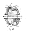
- Fig. 45 it is a rotary type embodiment of the present design, and on the passive body which is used as fixed body, there designed explosive exhaust gas chamber set Cy 105 and intake compressive gate Gx 1040; and on the active body which is used as motion body, there designed explosive exhaust gate Gy 1050, intake compressive gas chamber Cx 104, and intake port 11 0', exhaust port 111
- Fixed body possesses gas chamber set Cy 104 and gate plate driving seat 107, on the rotary trace of intake compressive gas chamber Cx 104 corresponding to motion body, there is gate plate Gx 1040 extending out of intake compressive gas chamber Cx 104 which closely sticks against stator, at the leading end of gas chamber Cx 104, there designed intake port z, this intake port 110' is placed at the position which can avoid to be interferred by gate plate Gx 1040 for guiding through gas chamber set Cx 104 and intake duct; exhaust port 111' is placed at the leading end of gate plate set Gy 1050 on the motion body and coupled with gas chamber set Cy 105 on fixed body; plug 108 or fuel nozzle 109 of the present design is placed in the concave structure 105" on the trace of gas chamber Cy 105 which is placed at the lagging end of gate plate set Gy 1050 on active body and corresponds to rotor, or placed in the concave chamber 105" which is placed at the leading end of gas shamber set Cy 105 on the passive body and can
- exchanging gas is that a guide groove 104" which is placed at the lagging end of intake compressive gas chamber Cx 104 of motion body near side of gas chamber Cy 105 turning back to the leading end and guide transverse groove 105' which is assembled on the explosive exhaust gas chamber Cy 105 of fixed body and extends to gas chamber set Cx 104 and communicated each other in order to transmit fuel gas when rotary phase is overlapped, and on the lagging trace of guide groove of active vody turning back to gas chamber set Cx 104, there further assembled a pressure-saved gas chamber CP z which intersects guide transverse groove 105' of gas chamber set Cy 105 and gas chamber Cy 105, and is separated from guide transverse groove 105' before exhaust of this cycle in order to save high pressure fuel gas of this cycle and mix with fresh fuel gas in the next cycle for promoting pressure of fresh fuel gas to be ignited and burned.
- a guide groove 104" which is placed at the lagging end of intake compressive gas chamber Cx 104 of motion body near side of gas chamber
- intake port 110', exhaust port 111' are assembled on fixed body, and intake port 110' is placed at the lagging end of gate plate set Gx 1040 to couple with trace of gas chamber Cx 104, exhaust port 111' is placed at the lagging end and can avoid to be interferred by gate plate Gy 1050 and can guide through gas chamber Cy 105 to exhaust waste gas.
- Fuel gas exchange structure constituted by guide hole of gate plate and gas guide passage of active body, relates to
- GTx possesses guide hole 1020 facing to compressive side
- GTy possesses guide hole 1030 facing to explosive side.
- guide holes 1020, 1030 of said gate plate set GTx 1045, GTy 1055 can slide according to the depth of gas chambers Cx 104, Cy 105 and communicate each other through gas guide passage 1010 between gate plate seat 1074 of above gate plate set GTx 1045 and gate plate seat 1075 of GTy 1055, its characteristic is to assemble gas guide passage on active body between two gate plate sets GTx 1045, GTy 1055 which is closely sealed by side of GTx 1045, GTy 1055 to form a sealed surface, GTx 1045, GTy 1055 rrspectively assembles guide gas chambers 1020, 1030 which are opposite in direction, and gradually raised and lowered cross section fo Cx 104 and Cy 105 is used for driving GTx 1045, GTy 1055 to transfer up and down.
- Intake compressive gate GTx 1045 faces to compressive surface and at least possesses an intake port 1020 which communicates from inner of gate plate to the exchange side near gas chamber set Cy 105; explosive exhaust gate Gy faces to explosive surface and at least possesses a guide hole 1030 which communicates from inner of gate plate to the exchange side near gas chamber set Cx 104, two guide holes are communicated each other through gas guide passage 1010 of active body when gate plate slide up and down to the eheight of exchange gas, height of exchange gas is between the highest points or between the highest point and the lowest point of gate plate set GTx 1045 and Gty 1055, it means that the gradually promoted section of gate plate set GTx 1045 which almost completes compression and the gradually lowered section of gate plate set GTy 1055 which slides into Cy 105 are the height of exchange gas, its working procedure is shown in Figs.
- Guide hole 1030 of GTy 1055 can further be slightly large chamber type for saving pressure and the return combustion of waste gas, and further assemble a groove 1000 in gas guide passage 1010 of active body for placing the adjusting plug 151.
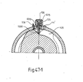
- FIGs. 47 and 47-1 wherein gate plate GTy 1055 possesses guide hole 1030, and at the lagging end of gas chamber set Cx 104 near side of GTy 1055, there possesses a transverse guide groove 104 , active body designes gas guide passage 1010 communicates from gate plate seat 1075 of GTy 1055 near side of gas chamber set Cx 104 to the postion coupling with trace of guide transverse groove 104 of gas chamber set Cx and matches height of exchange fuel gas of guide hole 1030 in GTy 1055, when GTy 1055 raises up to guide hole 1030 through gas guide passage 1010 and communicates above guide transverse groove 104 , fuel gas of gas chamber Cx 104 is transmitted through guide transverse groove 104 to the gas guide passage 1010 of active body and then enters into guide hole 1030 of gate plate set GTy 1055 to be transmitted to gas chamber Cy 105, its working procedure is shown in Figs. 47-2 and 47-3.
- And depth of gas chamber Cy 105 can be further selected, as shown in Fig. 48, due to the leading end is deeper and the lagging end is shallower, in the stroke, guide hole 1030 of shallower section of gas chamber Cy 105 is hidden into gate plate seat 107 of gate plate set GTy 1055 and let high pressure fuel gas be saved in it for mixing with fresh fuel gas in the next cycle.
- Figs.49 and 49-1 are the another embodiment, in which, GTx 1045 possesses guide hole 1020, and at the leading end of gas chamber setCy 105 near side of gas chamber set Cx 104, there is a guide transverse groove 105', and active body assembles gas guide passage 1010 which communicates from gate plate seat 1074 of GTx 1045 near side of gas chamber set Cy 105 to the position coupling with trace of guide transverse groove z of gas chamber set Cy and matches the height of exchange fuel gas of guide hole 1020 in GTx 1045, when GTx 1045 raises up to guide hole 1020 through gas guide passage 1010 and communicates above guide transverse groove 105', fuel gas of gas chamber Cx 104 is transmitted through guide hole 1020 of gate plate set GTx 1045 into gas guide passage 1010 and then passes through guide transverse groove 105' of gas chamber set Cy 105 and enters into the leading end of gas chamber set Cy 105 to be ignited and burned, its working procedure is shown in Figs.
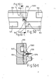
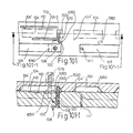
- fuel gas exchange structure constituted by guide hole of gate plate set and gas guide passage of active body is applied on linear type and rotary type embodiments in which active body is used as fixed body or active body is used as motion body, and its intake port 110' and exhaust port 111' are placed according to the principle of placement of each embodiment as mentioned in Item 1 of this section, and the principle of placing plug 108 or fuel nozzle 109 is as same as above-mentioned embodiment, furthermore, it also can be shown in Figs. 50 and 50-1, plug 108 and fuel nozzle 109 are penetrated and placed in the gas guide passage 1010 of active body and before ignition and combustion, GTx 1045 and intake compressive gas chamber set Cx must be separated each other.
- Function of saving pressure and return combustion of waste gas is to use gas guide passage 1010 of active body as pressure-saved chamber, and size of working angle which is formed by intersecting gas guide passage 1010 and guide transverse groove 105' of gas chamber Cy 105 can change the saved pressure.
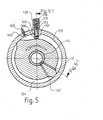
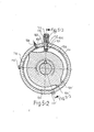
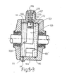
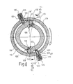
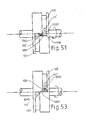
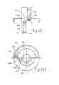
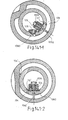
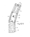
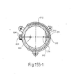
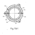
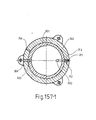
- Exchange gas chamber CZ 1060 of this design is placed at the position of active body, from axial view, it is obliquely between intake compressive gate GX 1040 and explosive exhaust gate Gy 1050 and can be rectangular groove as shown in Fig. 51 or oval-shaped groove as shown in Fig. 52 for being placed to stride between gas chamber set Cx 104, Cy 105 and avoid to occupy working angle and obtain gas chamber set Cx 104, Cy 105 which length is longer than direct stridding type one in order to increase the effective working angle.
- Main chamber of exchange gas chamber is located on the trace of gas chamber Cy and transversely strides over gas chamber Cx by inclined guide groove.
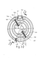
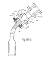
- Exchange gas chamber possesses a spherical main chamber and inclined guide groove, main chamber is located on the rotary trace of explosive exhaust gas chamber Cy 105, and strides a smaller guide groove in the direction of rotary trace of intake compressive gas chamber Cx 104, and obliquely extending direction of said guide groove is decided by the phase relationship between the lagging end of gas chamber Cx 104, and the leading end of gas chamber Cy 105 in the gas chamber set of same working cycle, and extending to the lagging direction in certain slope as shown in Fig. 53, or extending to the leading direction as shown in Fig. 54, or extending in turning method as shown in Figs.
- overlapping area of exchange gas chamber CZ 1060 and main chamber can obtain saved pressure in exchange gas chamber CZ 1060 after separating exchange gas chamber CZ 1060 and Cy 105, and before communicating Cy 105 and ignition again.
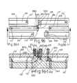
- Fig. 56 is an embodiment which transmit fuel gas by outer duct 160, in figure, on active body, hole 161 joining with duct respectively leads to gas chamber set Cx 104, Cy 105 or guide transverse groove 104', 105 to substitute for exchange gas chamber CZ 1060 on the coupling curface of active body and passive body.
- gas chambers Cx 104, Cy 105 communication of gas chambers Cx 104, Cy 105 is to assemble guide transverse groove z at lagging end of gas chamber set Cx 104 near side of Cy 105 for transmitting fuel gas, a section of working angle in motion is overlapped and communicated by exchange gas chamber which is coupled by the trace of gas chamber Cy 105 and guide transverse groove 104 , and is not coupled directly by gas chamber set Cx 104, in order to transmit fuel gas.
- Exchange gas chamber groove or guide transverse groove possesses turbulent structure of turbulent column, barrier, hole, granules, curved path.
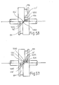
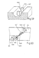
- Exchange gas chamber or guide transverse groove used for transmitting fuel gas from gas chamber Cx 104 to gas chamber Cy 105 as abobe-mentioned can further assemble column type turbulent structure 1060 which can possesses function of turbulence as shown in Fig. 59, barrier type 1062 as shown in Fig. 60, hole type 1063 as shown in Fig. 61, granule type 1064 as shown in Fig. 62, or curved type guide groove 1065 as shown in Fig. 63, or structure of each set of small thin tube 1066 as shown in Fig. 64 in order to let the mixture of fuel gas mix in average.
- exchange gas chamber CZ 1060 of this design only communicates gas chambers Cx 104, Cy 105 in exchange of fuel gas, and before explosion, CZ 1060 is firstly separated from gas chamber Cy 105, and then CP 1060' and guide transverse groove 105' of gas chamber Cy 105 communicates each other and then ignite fuel gas, and after CP 1060' is separated from guide transverse groove 105', Cy 105 begins to exhaust, its working procedure is shown in Figs.
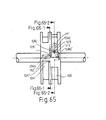
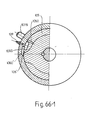
- Figs. 66, 66-1 at side of gas chamber Cy 105 of passive body not near gas chamber set Cx 104, there designed a guide transverse groove 105', at lagging end, there designed an auxiliary pressure-saved chamber CPS 1060 , when at the moment of CPS 1060 and CP 1060 communicate guide transverse groove 105', before ignition of fuel gas, high pressure waste gas stored in the last cycle is released from CP z and CPS 1060", and before exhaust of this cycle, it is separated from guide transverse groove z of gas chamber set Cy 105, in order to save the high pressure waste gas of this cycle, its working procedure is shown in Figs. 66-2, 66-3.
- exchange gas chamber CZ 1060 and pressure-saved gas chamber CP 1060' are positioned on a same trace, exchange gas chamber CZ 1060 is at the leading place, CP 1060' is at the lagging place, and both of them are in the middle of trace of gas chamber Cx 104, Cy 105, and communicate gas chambers Cx 104, Cy 105 on proper time, it means that exchange gas chamber set CZ 1060 and pressure-saved gas chamber CP 1060 are respectively assembled as independent gas chamber, CP 1060' is between the driving traces of intake compressive gas chamber Cx 104 and explosive exhaust gas chamber Cy 105 and at the lagging end of exchange gas chamber 1060; its method of exchanging fuel gas is to push and compress fuel gas of gas chamber Cx 104 by gate plate Gx
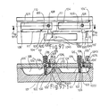
- the present design is to dig a hole 152 for screwing pressure release valve 150 on structure of exchange gas chamber CZ 1060 or pressure-saved gas chamber CP 1060', or auxiliary pressure-saved chamber 1060", critical pressure of constant pressure release valve 150 can be further adjusted.
- exchange gas chamber is directly formed by coupling with engine body, it also can be shown in Gis. 69, as an independent plug type structure of exchange gas chamber CZ 1060 in order to plug in or screw on the active body of gate plate set Gy 1050, on the independent plug type exchange gas chamber, it can assemble plug 108 or fuel nozzle 109 or both of them.
- This independent plug type exchange gas chamber CZ 1060 can be placed on the active body which can be used as fixed body or motion body, and can assemble pressure release valve 150 of it is necessare.
- the pressure release valve On the pressure release valve, it possesses an adjusting plug 151 which is placed in the screw hole or groove type structure 152 of active body and joined by screw or groove, and is locked and fixed on the active body by fixing screw nut, screw or button ring or pin, it is adjusted and locked by rotating or sliding in order to change the volume of exchange gas chamber.
- exchange gas chamber CZ 1060 In rotary or linear motion, above exchange gas chamber CZ 1060 will communicate explosive exhaust gas chamber Cy 105 and then ignite and explode after exchange gas chamber slides away from gas chamber Cx 104, explosive pressure of fuel gas in gas chamber Cy 105 will distribute at the leading end of gate plate Cy 1050 of gas chamber Cy 105 and in exchange gas chamber CZ 1060, motion body is driven to gas chamber Cy 105, before exhaust, gas chamber Cy 105 is firstly separated from exchange gas chamber CZ 1060 in order to save high pressure fuel gas in exchange gas chamber CZ 1060.
- this kind of function includes gas chamber sets which are in the same body or in the different bodies, and method of transmitting fuel gas, and the relationship of series connection or parallel connection between gas chamber set Cx 104 and Cy 105, and dynamic set in which above-mentioned multi-sectional gas chamber Cx 104 is matched by single set gas chamber Cy 105, or multi-row gas chamber 104 is matched by single set gas chamber Cy 105 to form a dynamic set, and structural selection of method of matching multi-set intake compressive gate plate set Gx 1040 with gas chamber Cx 104.
- Gate plate set internal combustion engine twice help combustion structure includes the following main designs:
- Structural relation between active body and passive body is that active body is used as fixed body.
- passive body is used as motion body.
- Gas chamber sets Cx 104 and Cy 105 Relation between gas chamber sets Cx 104 and Cy 105 is that gas chamber set Cx is placed at passive body; gas chamber set Cy is placed at passive body: gas chamber sets Cx and Cy are placed in series connection.
- Gate plate set Characteristic of gate plate set is that common gate plate GC 106 is in front, and gate GS 1048 with panetrating hole is in rear.
- Intake compressive structure with function of twice help combustion is to place multi-set gate plate set GC 106, GP 1046 on single-set gas chamber set Cx 104, and possesses independent or common intake ports.
- Fuel gas is transmitted from gas chamber set Cx 104 to gas chamber set Cy 105 by common gate plate set GC 106 and GP 1046 with pressure-saved gas chamber 102 and low position intake valve 101, and high position output guide hole 103.
- Method and device of ignition and combustion include that plug ignites the mixed gas, or fuel nozzle injects fuel to mix with and ignite high pressure high temperature air, or the burned high termerature fuel is used to ignite fresh fuel.
- Ignition device is placed in the concave chamber structure which is at the lagging end of gate plate set GC 106 of active body and can couple with gas chamber Cy, and avoid to be interferred by passive body; or it is placed in the concave chamber which is at the leading end of gas chamber set Cy 105 of passive body and can avoid to be interferred by gate plate GP 1046 or gate plate GC 106.
- intake method respectively possesses independent intake port which is placed at the active body used as fixed body, and each intake port is respectively placed at side of each gate plate set GC 106 and GP 1046 and coupled by intake guide transverse groove 104 of gas chamber set Cx 104.
- exhaust method is to be placed at the active body which is used as fixed body, and wxhaust port 111' is placed at the side of leading end of gate plate set GC 106, and couples with wxhaust guide transverse groove 105' of gas chamber set Cy 105;
- exhaust port 111' is respectively placed in the hole structure which is at the lagging end of each gas chamber set Cy 105, and can avoid to be interferred by gate plate set GC 106, and transmit fuel gas through transmission pipe which is coupled by exhaust port 111' on motion body; or it is respectively placed in groove type structure which is at the lagging end of each gas chamber set Cy 105 and can avoid to be interferred by gate plate set GC 106 and transmit fuel gas through transmission pipe which is coupled by exhaust groove 111 on motion body.
- Each dynamic cycle is constituted by a set of gas chamber set Cx 104 and Cy 105.
- Time of help combustion can be set by the difference of working angle of gate plate set GC 106 and GP 1046.
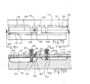
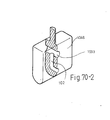
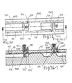
- gate plate set GP 1046 with penetrating hole, as shown in Fig. 70-2, at the surface which faces to the motion body and is near the coupled contact end of gas chamber, there places one-way intake valve 101, in the gate body, there possesses pressure-saved chamber 102, at the far distance, there possesses a guide hole 1033 which penetrates the leading end and the lagging end of gate plate set GP 1046.
- Gas chamber set Cx 104 is shallower and when gate plate set GC 106 and GP 1046 slides in, one-way intake valve can expose and face to the gas which will be compressed, and guide hole 103 of gate plate set GC and penetrating guide hole 1033 of GP 1046 are hidden into gate plate seat.
- Gas chamber set Cy is deeper or its leading section is deeper, and when gate plate set GC 106 and GP 1046 slide into the deeper section, guide hole 103 of gate plate set GC 106 and penetrating guide hole 1033 of GP 1046 expose outside gas chamber.
- ventilated crack which can avoid to the resistance caused by the pressure difference of two ends of gate plate before rrleasing the gas of pressure-saved chamber 102 in the instant of gate plate set to slide into, and ventilated crack is in the front of working angle of pressure-saved chamber for releasing gas.
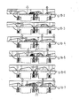
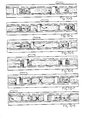
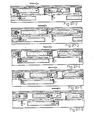
- Figs. 70-3 to 70-8 are the working procedure diagrams of above twice help combustion embodiment A in which active body is used as fixed body, gas chambers Cx, Cy are connected in series in the same body, and possess single-set gas chamber Cx, multi-set gate plate Gx. Its working cycle is shown in Table 8.
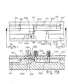
- Figs 71 and 71-1 are the graphic views of twice help combustion embodiment B in which gas chambers Cx, Cy are connected in series in the same body and possess single-set gas chamber Cx, multi-set gate plate Gx, and its main characters are as follows:
- Twice help combustion intake compressive structure is to place multi-set gate plate GC 106, GP 1046 on single-set gas chamber set Cx 104, and possesses common intake port 110'.
- intake port 110' is placed at side of lagging end of gate plate set GC 106 and couples with intake guide transverse groove of gas chamber set Cx;
- intake port 110' is placed in the hole structure which is at the leading end of gas chamber Cx 104 and can avoid to be interferred by gate plate set GC 106, and transmit fuel gas through transmission pipe which is coupled on the intake port 110' on motion body; or it is placed in the groove type structure which is at the leading end of gas chamber Cx 104 and can avoid to be interferred by gate plate set GC 106, GP 1046 and transmit fuel gas through transmission pipe which is coppled by intake groove 110 on motion body.
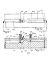
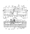
- Figs. 72 and 72-1 are the graphic views of twice help combustion embodiment in which active body is used as motion body, gas chambers Cx, Cy are connected in series in the same body, and possess gas chamber Cx, multi-set gate plate Gx, and its main characters are as follows:
- Structural relation between active body and passive body is that active body is used as motion body; passive body is used as fixed body.
- Relation between gas chamber sets Cx 104 and Cy 105 is that gas chamber set Cx is placed at passive body, gas chamber set Cy is placed at passive body; gas chamber sets Cx and Cy are placed in series connection.
- Gate plate set Characteristic of gate plate set is that common gate plate GC 106 is in front, and gate GP 1046 with penetrating hole is in rear.
- Intake compressive structure with function of twice help combustion is to place multi-set gate plate set GC 106, Gp 1046 and possesses common intake port 110'.
- Fuel gas is transmitted from gas chamber set Cx 104 to gas chamber set Cy 105 by common gate plate set GC 106 and GP 1046 with pressure-saved gas chamber 102 and low position intake valve 101, and high position output guide hole 103.
- Method and device of ignition and combustion include that plug ignites the mixed gas, or fuel nozzle injects fuel to mix with and ignite high pressure high temperature air, or the burned high temperature fuel is used to ignite fresh fuel.
- Ignition device is placed in the concave chamber structure which is at the lagging end of gate plate set GC 106 of active body and can couple with gas chamber Cy and avoid to be interferred by passive body; or it is placed in the concave chamber which is at the leading end of gas chamber set Cy 105 of passive body and can avoid to be interferred by gate plate GP 1046 or gate plate GC 106.
- intake method respectively possesses independent intake port which is placed at the passive body used as fixed body, and intake port 110' is placed in the hole structure or guide transverse groove which is at the leading end of gas chamber set Cx 104, and can avoid to be interferred by gate plate set GC 106;
- intake port 110' is placed at side of lagging end of and couples with intake guide transverse groove of gas chamber set Cx and can transmit fuel gas through transmission pipe which is coupled by intake port 110' on motion body.
- exhaust port 111' is placed in the hole structure which is at the lagging end of gas chamber set Cy 105 and can avoid to be interferred by gate plate set GC 106;
- exhaust port 111' is respectively placed at side of leading end of each gate plate set GC 106, and couples with exhaust guide transverse groove 105' of gas chamber set Cy 105 and can transmit fuel gas through transmission pipe which is coupled by exhaust port 111' on motion body.
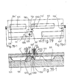
- Gigs. 73 and 73-1 are the graphic views of twice help combustion embodiment in which active body is used as fixed body, gas chambers Cx, Cy are connected in series in the same body and possess multi-set gas chamber Cx, single-set gate plate Gx, and its main characters are as follows:
- Atructural relation between active body and passive body is that active body is used as fixed body; passive body is used as motion body.
- Gas chamber sets Cx 104 and Cy 105 Relation between gas chamber sets Cx 104 and Cy 105 is that gas chamber set Cx is placed at passive body; gas chamber set Cy is placed at passive body; gas chamber sets Cx and Cy are placed in series connection.
- Gate plate set possesses transverse guide hole gate GTx 1045, and each set is placed at interval of 120° working angle.
- Intake compressive structure with function of twice help combustion is constituted by connecting multi-set gas chamber Cx 104 in series and on which there has independent intake port z.
- Fuel gas is transmitted from gas chamber set Cx 104 to gas chamber set Cy 105 by gate plate set GTx 1045 with guide hole 1020, transverse guide pass 1010 of active body, and guide transverse groove 105' of gas chamber set Cy 105.
- Method and device of ignition and combustion include that plug ignites the mixed gas, or fuel nozzle injects fuel to mix with and ignite high pressure high temperature air, or the burned high temperature fuel is used to ignite fresh fuel.
- Ignition device is placed in the concave chamber structure which is at the lagging end of gate plate set GTx 1045 of active body, and can avoid to be interferred by passive body; or it is placed in the guide groove 1010 of active body; or it is placed in the concave chamber which is at the leading end of gas chamber set Cy 105 of passive body and can avoid to be interferred by gate plate GTx 1045.
- intake method respectively possesses independent intake port which is placed at the active body used as fixed body, and each sectional intake port 110' is respectively placed at the lagging end of each gate plate set GTx 1045, and coupled by intake guide transverse groove 104' of gas chamber Cx 104';
- intake port l 10' is respectively placed in the hole structure which is at the leading end of each gas chamber Cx 104 and can avoid to be interferred by gate plate set GTx 1045 and transmit fuel gas through transmission pipe which is coupled by intake port on motion body.
- exhaust method is to plate exhaust port on the active body which is used as fixed body, and exhaust port 111' is placed at the side of leading end of gate plate set GTx 1045 and is coupled by exhaust guide transverse groove 105' of gas chamber set Cy 105;
- exhaust port 111' is respectively placed in the hole structure which is at the lagging end of each gas chamber set Cy 105 and can avoid to be interferred by gate plate set GTx 1045, and transmit fuel gas through transmission pipe which is coupled by exhaust port 111' on motion body; or it is respectively placed in the groove type structure which is at the lagging end of each gas chamber set Cy 105 and can avoid to be interferred by gate plate set GTx 1045, and can transmit fuel gas through transmission pipe which is coupled by exhaust groove 111 on motion body.
- Intake compression gas chamber which is constituted by two sectional gas chamber set Cx 104 is connected in series by a set of explosive exhaust gas chamber set Cy 105 and used as passive body.
- the coupled and guided position of gate plate set GTx 1045 between the leading gas chamber set and the lagging gas chamber set and transverse guide hole 1010 of active body is the point of exchanging gas.
- the largest length from ignition point to the lagging end on gas chamber set Cy 105 is the length of 120° working angle
- the largest length of the leading gas chamber set Cx 104 is 120° working angle
- the lagging set of gas chamber set Cx 104 is designed to be closely behind the leading set
- the gradually raising surface of lagging end lets the position which gate plate set GTx 1045 is coupled and guided again by transverse guide hole 1010 of active body is the point of help combustion
- its length is similar to the corresponding length of working angle from ignition, combustion to twice help combustion.
- Each dynamic unit includes a set of gas chamber set Cy 105, and intake compressive gas chamber set which is constituted by a set of leading gas chamber and a set of lagging gas chamber, and three sets of gate plate set GTx 1045 and it is placed at interval of 120° working angle.
- Guide groove which is placed on active body and coupled with transverse guide hole 1020 wxtends toward the leading end of GTx 1045 to the position which it can be coupled by guide transverse groove 105' of gas chamber set Cy 105.
- Ignition point, exchange gas point, and the interval point between gas chamber Cy 105 and the leading gas chamber set Cx are distanced with 120° working angle.
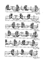
- Figs. 73-2 to 73-7 are the working procedure diagrams of above twice help combustion in which active body is used as fixed body, gas chambers Cx, Cy are connected in series in the same body, and possess multi-set gas chamber Cx, single-set gate plate Gx. Its working cycle is shown in Table 9.
- Figs. 74 and 74-1 are the graphic view of twice help combustion embodiment in which active body is used as motion body, gas chambers Cx, Cy are connected in series in the same body and possess multi-set gas chamber Cx, single-set gate plate Gx, and its main characters are as follows:
- Structureal relation between active body and passive body is that active body is used as motion body; passive body is used as fixed body.
- Gas chamber sets Cx 104 and Cy 105 Relation between gas chamber sets Cx 104 and Cy 105 is that gas chamber set Cx is placed at passive body; gas chamber set Cy is placed at passive body; gas chamber sets Cx and Cy are placed in series connection.
- Gate plate set possesses transverse guide hole gate GTx 1045, and each set is placed at interval of 120° working angle.
- Intake compressive structure with function of twice help combustion is constituted by connecting multi-set gas chamber Cx 104 in series and on which there has independent intake port 110'.
- Fuel gas is transmitted from gas chamber set Cx 104 to gas chamber set Cy 105 by gate plate set GTx 1045 with guide hole 1020, transverse guide pass 1010 of active body, and guide transverse groove 105' of gas chamber set Cy 105.
- Method and device of ignition and combustion include that plug ignites the mixed gas, or fuel nozzle injects fuel to mix with and ignite high pressure high temperature air, or the burned high temperature fuel is used to ignite fresh fuel.
- Ignition device is placed in the concave chamber structure which is at the lagging end of gate plate set GTx 1045 of active body, and can avoid to be interferred by passive body; or it is placed in the guide groove 1010 of active body; or it is placed in the concave chamber which is at the leading end of gas chamber set Cy 105 of passive body and can avoid to be interferred by gate plate GTx 1045.
- intake method respectively possesses independent intake port which is placed at the active body used as fixed body, and each sectional intake port is respectively placed in the hole structure which is at the leading end of each gas chamber set Cx 104, and can avoid to be interferred by gate plate set GTx 1045;
- intake port is respectively placed at side of each gate plate set GTx 1045 and coupled with intake guide transverse groove 104 at the leading end of gas chamber set Cx 104, and can transmit fuel gas through transmission pipe which is coupled by intake port 110' on motion body.
- exhaust method is to place exhaust port on the passive body which is used as fixed body, and exhaust port 111' is placed in the hole structure which is at the lagging end of gas chamber set Cy 105, and can avoid to be interferred by gate plate set GTx 1045;
- exhaust port 111' is respectively placed at side of leading end of each gate place set GTx 1045, and is coupled by exhaust guide transverse groove 105' which is at the lagging end of gas chamber set Cy 105, and can transmit fuel gas through transmission pipe which is coupled by exchaust port 111' on motion body.
- Figs. 75 and 75-1 are the graphic views of twice help combustion embodiment A in which active body is used as fixed body, gas chambers Cx, Cy are connected in parallel in the same body, and possess single-set gas chamber Cx, multi-set gate plate set Gx, and its main characters are as follows:
- Structural relation between active body and passive body is that active body is used as fixed body; passive body is used as motion body.
- Relation between gas chamber sets Cx 104 and Cy 105 is that gas chamber set Cx is placed at passive body; gas chamber set Cy is placed at passive body; gas chamber sets Cx and Cy are placed in parallel connection.
- Gate plate Characteristic of gate plate is that each dynamic unit possesses multi-set Gx 1040 and single-set Gy 1050.
- Intake compressive structure with function of twice help combustion is to place multi-set gate plate set Gx 1040 on signle-set gas chamber Cx 104, and possesses common intake port z.
- Fuel gas is transmitted by exchange gas chamber CZ 1060 or groove on active body from gas chamber set Cx 104 to gas chamber Cy 105.
- Method and device of ignition and combustion include that plug ignites the mixed gas, or fuel nozzle injects fuel to mix with and ignite high pressure high temperature air, or the burned high temperature fuel is used to ignite fresh fuel.
- Ignition device is placed in the exchange gas chamber CZ 1060 of active body; or it is placed in the concave chamber structure which is at the lagging end of gate plate set Gy 1050 of active body and can couple with gas chamber Cy, and avoid to be interferred by passive body; or it is placed in the concave chamber which is at the leading end of gas chamber set Cy 105 of passive body and can avoid to be interferred by gate plate Gy 1050.
- intake method possesses common intake port which is placed at the active body used as fixed body, and intake port 110' is placed at side of lagging end of gate plate set Gx 1040, and is coupled by intake guide transverse groove of gas chamber set Cx;
- intake port 110' is placed in the hole structure at the leading end of gas chamber Cx 104 and can avoid to be interferred by gate plate set Gx 1040, GC 1060, and transmit fuel gas through transmission Pipe which is coupled by intake port 110' on motion body; or it is placed in the groove type structure which is at the leading end of gas chamber Cx 104 and can avoid to be interferred by gate plate set Gx 1040, GC 106, GTx 1045, and transmit fuel gas through transmission pipe which is coupled by intake groove 110 on motion body.
- exhaust port 111' is placed at the leading end of gate plate set Gy 1050 and couples on the track of gas chamber Cy 105; or it is placed at side of leading end of gate plate set Gy 1050, and is coupled by exhaust guide transverse groove 105' of gas chamber set Cy 105;
- exhaust port 111' is respectively placed in the hole structure which is at the lagging end of each gas chamber set Cy 105, and can avoid to be interferred by gate plate set Gy 1050, and transmit fuel gas through transmission pipe which is coupled by exhaust port 111' on motion body; or it is respectively placed in the groove type structure which is at the lagging end of each gas chamber set Cy 105 and can avoid to be interferred by gate plate set Gy 1050, and transmit fuel gas through transmission pipe which is coupled by exhaust port 111 on motion body.
- Gate plate set Gy 1050 at least is coupled by a set of gas chamber Cy;
- Each dynamic unit is constituted by serial connection of a set of gas chamber which is matched by two gate plate sets Gx 1040, and a set of gas chamber set Cy 105 which is matched by a set of gate plate set Gy 1050;
- Two sets of exchange gas chamber is placed between gas chambers Cx 104 and Cy 105 and only intersect guide transverse grooves 104 and 105' to transmit fuel gas during driving, and its leading set is placed at the lagging end of the leading gate plate set Cx, and its lagging set is placed at the lagging end of the lagging gate plate set Cy;
- Time of twice help combustion is after fuel gas of gas chamber set Cy 105 is ignited;
- exchange gas chamber CZ 1060 of the lagging set intersects and communicates guide groove 104 of gas chamber set Cy 105, and then intersects guide transverse groove 105 of gas chamber set Cy 105, exchange gas chamber CZ 1060 of the lagging set, intersects and communicates guide transverse grooves 104 and 105' in difference in order to prevent fuel gas flowing to gas chamber set Cx 104.
- exchange gas chamber CZ 1060 of the lagging set separates from guide transverse groove 105 of exchange gas chamber Cy to store high pressure fuel gas for the return combustion of the saved pressure.
- Figs. 75-2 to 75-7 are the working procedure diagrams of above twice help combustion embodiment A in which active body is used as fixed body, gas chambers Cx, Cy are connected in parallel in the same body, and possess single-set gas chamber Cx, multi-set gate plate set Gx, and its working cycle is shown in Table 10.
- Figs. 76 and 76-1 are the graphic views of twice help combustion embodiment B in which active body is used as fixed body, gas chambers Cx, Cy are connected in parallel in the same body and possess single-set gas chamber Cx, multi-set gate plate set Gx, and its main characters are as follows:
- Intake compressive structure with function of twice help combustion is to place multi-set gate plate set Gx 1040 on single-set gas chamber set Cx 104 and possesses independent intake port 110'.
- each independent intake port is assembled on the active body which is used as fixed body, and intake port 110' is respectively placed at side of each gate plate set Gx 1040 to couple with intake guide transverse groove 104 of gas chamber set Cx 104.
- Figs. 77 and 77-1 are the graphic views of twice help combustion embodiment in which active body is used as motion body, gas chambers Cx, Cy are connected in parallel in the same body and possess single-set gas chamber Cx, multi-set gate plate set Gx, and its main characters are as follows:
- Structural relation between active body and passive body is that active body is used as motion body; passive body is used as fixed body.
- Relation between gas chamber sets Cx 104 and Cy 105 is that gas chamber set Cx is placed at passive body; gas chamber set Cy is placed at passive body; gas chamber sets Cx and Cy are placed in parallel connection.
- Gate plate set Characteristic of gate plate set is that each dynamic unit possesses multi-set GX 1040 and single-set Gy 1050.
- Intake compressive structure with function of twice help combustion is to place multi-set gate plate set Gx 1040 on single-set gas chamber set Cx 1040 and possesses common intake port z.
- Fuel gas is transmitted by exchange gas chamber CZ 1060 or groove on active body from gas chamber set Cx 104 to gas chamber set Cy 105.
- Method and device of ignition and combustion include that plug ignites the mixed gas, or fuel nozzle injects fuel to mix with and ignite high pressure high temperature air, or the burned high temperature fuel isused to ignite fresh fuel.
- Ignition device is placed in the exchange gas chamber CZ 1060 of active body; or it is placed in the concave chamber structure which is at the lagging end of gate plate set Gy 1050 of active body and can couple with gas chamber Cy, and avoid to be interferred by passive body; or it is placed in the concave chamber which is at the leading end of gas chamber set Cy 105 of passive body and can avoid to be interferred by gate plate Gy 1050.
- intake method possesses common intake port which is placed at the active body used as fixed body, and intake port 110' is placed in the hole structure or guide transverse groove which is at the leading end of gas chamber set Cx 104 and can avoid to be interferred by gate plate set Gx 1040;
- intake port is placed at the lagging end of gate plate set Gx 1040 and is coupled on the track of gas chamber Cx, and can transmit fuel gas through transmission pipe which is coupled by intake port 110' on motion body; or it is placed at side of lagging end of gate plate set Gx 1040, Gtx 1045, and is coupled by intake guide transverse groove 104 of gas chamber set Cx 104, and can rransmit fuel gas through transmission pipe which is coupled by intake port 110' on motion body.
- exhaust method is to place exhaust port on the passive body which is used as fixed body, and exhaust port 111' is placed in the hole structure which is at the lagging end of gas chamber set Cy 105, and can void to be interferred by gate plate set Gy 1050;
- exhaust port 111' is placed at the leading end of gate plate set Gy 1050, and couples on the track of gas chamber Cy, and can transmit fuel gas through transmission pipe which is coupled by exhaust port 111' on motion body; or it is respectively placed at side of leading end of gate plate set Gy 1050, and is coupled by exhaust guide transverse groove 105' of gas chamber set Cy 105, and can transmit fuel gas through transmission pipe which is coupled by exhaust port 1111 on motion body.
- Figs. 78 and 78-1 are the graphic views of twice help combustion embodiment A in which active body is used as fixed body, gas chambers Cx, Cy are connected in parallel in the same body, and possess multi-set gas chamber Cx, single-set gate plate Gx, and its characters are as follows:
- Structural relation between active body and passive body is that active body is used as fixed body; passive body is used as motion body.
- Gas chamber sets Cx 104 and Cy 105 Relation between gas chamber sets Cx 104 and Cy 105 is that gas chamber set Cx is placed at passive body; gas chamber set Cy isalso placed at passive body; gas chamber sets Cx and Cy are placed in parallel connection.
- Gate plate set Characteristic of gate plate set is to be constituted by gate plate set Gx 1040, Gy 1050 without guide hole.
- Intake compressive structure with function of twice help combustion is connected in series by multi-set gas chamber set Cx 104, and places independent or common intake port 110' on it.
- Fuel gas is transmitted by exchange gas chamber CZ 1060 or groove on active body from gas chamber set Cx 104 to gas chamber set Cy 105.
- Method and device of ignition and combustion include that plug ignites the mixed gas, or fuel nozzle injects fuel to mix with and ignite high pressure high temperature air, or the burned high temperature fuel is used to ignite fresh fuel.
- Ignition device is placed in the exchange gas chamber CZ 1060 of active body; or it is placed in the concave chamber structure which is at the lagging end of gate plate set Gy 1050 of active body and can couple with gas chamber Cy, and avoid to be interferred by passive body; or it is placed in the concave chamber which is at the leading end of gas chamber set Cy 105 of passive body and can avoid to be interferred by gate plate Gy 1050.
- intake method respectively possesses independent intake port which is placed at the passive body used as motion body, and intake port is respectively placed in the hole structure which is at the leading end of each gas chamber set Cx 104, and can avoid to be interferred by gate plate set Gx 1040;
- intake port 110 is placed at the side of lagging end of gate plate set Gx 1040 or Gc 106 or GTx 1045 and is coupled by intake guide transverse groove of gas chamber set Cx;
- intake port z is placed in the hole structure which is at the leading end of gas chamber Cx 104 and can avoid to be interferred by gate plate set Gx 1040 and transmit fuel gas through transmission pipe which is coupled by intake port 110' on motion body; or it is placed in the groove type structure which is at the leading end of gas chamber Cx 104 and can avoid to be interferred by gate plate set Gx 1040 and can transmit fuel gas through transmission pipe which is coupled by intake groove 110 on motion body.
- exhaust port 111' is placed at the leading end of gate plate set Gy 1050 and couples on the track of gas chamber Cy 105; or it is placed at side of leading end of gate plate set Gy 1050, and is coupled by exhaust guide transverse groove 105' of gas chamber set Cy 105;
- exhaust port 111' is respectively placed in the hole structure which is at the lagging end of each gas chamber set Cy 105, and can avoid to be interferred by gate plate set Gy 1050, and transmit fuel gas through transmission pipe which is coupled by exhaust port 111' on motion body; or it is respectively placed in the groove type structure which is at the lagging end of each gas chamber set Cy 105 and can avoid to be interferred by gate plate set Gy 1050, and transmit fuel gas through transmission pipe which is coupled by exhaust port 111 on motion body.
- Cy 105 is used as passive body
- Gate plate set Gx 1040 at least couples a set of intake compressive gas chamber set which is constituted by two sections of series connection gas chamber Cx 104;
- Gate plate set Gy 1050 at least couples a set of gas chamber set Cy 105;
- each section of gas chamber Cx 104 is near side of gas chamber set Cy, and there is guide transverse groove;
- Each dynamic unit is constituted by intake compressive gas chamber which is connected in series by a set of explosive exhaust gas chamber set Cy 105 and at least two sections of gas chamber Cx 104;
- the coupled track of wxchange gas chamber CZ 1060 is between gas chambers Co 104 and Cy 105, and intersects guide transverse grooves 104', 105' to transmit fuel gas;
- exchange gas chamber CZ 1060 intersects guide transverse groove 105' in the middle section of gas chamber set Cy 105 and transmit, and exchange gas chamber CZ 1060 and guide transverse grooves 104', 105 of gas chamber sets Cx 104, Cy 105 intersect and communicate at different time;
- Gate plates Gx 1040 and Gy 1050 can cover guide transverse grooves 104 , 105' when it intersects guide transverse grooves 104 and 105 during drive.
- Figs. 79 and 79-1 are the graphic views of twice help combustion embodiment B in which active body is used as fixed body, gas chambers Cx, Cy are connected in parallel in the same body and possess multi-set gas chamber Cx, single-set gate plate Gx, and its main characters are as follows:
- Active body is used as fixed body; passive body is used as motion body.
- At least a set of gas chamber Cy 105 is connected in parallel by gas chamber Cx 104 which is at least two times of series connection of Cy 105.
- Series connection gas chamber Cx 104 is used as common gate plate Gx 1040.
- Figs. 80 and 80-1 are the graphic views of twice help combustion embodiment in which active body is used as motion body, gas chambers Cx, Cy are connected in parallel in the same body, and possess multi-set gas chamber Cx, single-set gate plate Gx, and its main characters are as follows:
- Active body is used as motion body; passive body is used as fixed body.
- Gas chamber sets Cx 104 and Cy 105 Relation between gas chamber sets Cx 104 and Cy 105 is that gas chamber set Cx is placed at passive body; gas chamber set Cy is also placed at passive body; gas chamber sets Cx and Cy are placed in parallel connection.
- Gate plate set Characteristic of gate plate set is to be constituted by gate plate set Gx 1040, Gy 1050 without guide hole.
- Intake compressive structure with function of twice help combustion is connected in series by multi-set gas chamber set Cx 104, and places independent or common intake port 110' on it.
- Fuel gas is transmitted by exchange gas chamber CZ 1060 or groove on active body from gas chamber set Cx 104 to gas chamber set Cy 105.
- Method and device of ignition and combustion include that plug ignites the mixed gas, or fuel nozzle injects fuel to mix with and ignite high pressure high temperature air, or the burned high temperature fuel is used to ignite fresh fuel.
- Ignition device is placed in the exchange gas chamber CZ 1060 of active body; or it is placed in the concave chamber structure which is at the lagging end of gate plate set Gy 1050 of active body and can couple with gas chamber Cy, and avoid to be interferred by passive body; or it is placed in the concave chamber which is at the leading end of gas chamber set Cy 105 of passive body and can avoid to be interferred by gate plate Gy 1050.
- intake method respectively possesses independent intake port which is placed at the passive body used as fixed body, and intake port is respectively placed in the hole structure which is at the leading end of each gas chamber set Cx 104, and can avoid to be interferred
- intake port 110' is placed in the hole structure or guide transverse groove which is at the leading end of gas chamber set Cx 104, and can avoid to be interferred by gate plate set Gx 1040;
- intake port is placed at the lagging end of gate plate set Gx 1040 and is coupled on the track of gas chamber Cx, and transmit fuel gas through transmission pipe which is coupled by intake port 110' on motion body; or it is placed at side of lagging end of gate plate set Gx 1040 and is coupled by guide transverse groove, and can transmit fuel gas through transmission pipe which is coupled by intake port 110' on motion body.
- exhaust method is to place exhaust port on the passive body which is used as fixed body, and exhaust port 111' is placed in the hole structure which is at the lagging end of gas chamber set Cy 105, and can avoid to be interferred by gate plate set Gy 1050;
- exhaust port 111' is placed at the leading end of gate plate set Gy 1050, and couples on the track of gas chamber Cy, and can transmit fuel gas through transmission pipe which is coupled by exhaust port 111' on motion body; or it is respectively placed at side of leading end of each gate plate set Gy 1050, and is coupled by exhaust guide transverse groove 105' of gas chamber set Cy 105, and can transmit fuel gas through transmission pipe which is coupled by exhaust port 111' on motion body.
- Figs. 80-2 to 80-7 are the working procedure deagrams of twice help combustion embodiment in which active body is used as motion body, gas chambers Cx, Cy are connected in parallel in the same body, and possess multi-set gas chamber Cx, single-set gate plate Gx; and its working cycle is shown in Table 11.
- Twice help combustion structure possesses multi-row gas chamber Cx which connects single-set gas chamber Cy in parallel in the same body.
- Figs. 81 and 81-1 are the graphic views of twice help combustion embodiment in which active body is used as fixed body, and it possesses multi-row gas chamber Cx which is connected by single-set gas chamber Cy in parallel in the same body, and its main characters are as follows:
- Structure relation between active body and passive body is that active body is used as fixed body; passive body is used as motion body.
- Gas chamber sets Cx 104 and Cy 105 Relation between gas chamber sets Cx 104 and Cy 105 is that gas chamber set Cx is placed at passive body; gas chamber set Cy is also placed at passive body; gas chamber sets Cx and Cy are placed in parallel connection.
- Gate plate set Characteristic of gate plate set is to be constituted by gate plate set Gx 1040, Gy 1050 without guide hole.
- Intake compressive structure with function of twice help combustion which connects single-set gas chamber set Cy 105 in parallel by multi-row gas chambers set Cx 104, gas chamber set Cx 104 possesses independent intake port z.
- Fuel gas is transmitted by exchange gas chamber CZ 1060 or groove on active body from gas chamber set Cx 104 to gas chamber set Cy 105.
- Method and device of ignition and combustion include that plug ignites the mixed gas, or fuel nozzle injects fuel to mix with and ignite high pressure high temperature air, or the burned high temperature fuel is used to ignite fresh fuel.
- Ignition device is placed in the exchange gas chamber CZ 1060 of active body; or it is placed in the concave chamber structure which is at the lagging end of gate plate set Gy 1050 of active body and can couple with gas chamber Cy, and avoid to be interferred by passive body; or it is placed in the concave chamber which is at the leading end of gas chamber set Cy 105 of passive body and can avoid to be interferred by gate plate Gy 1050.
- intake method respectively possesses independent intake port which is placed at active body used as fixed body, and intake port 110' is respectively placed at the lagging end of each gate plate set Gx 1040 and is coupled on the track of gas chamber Cx 104; or intake port 110' is respectively placed at side of gate plate set Gx 1040 and is coupled by ntake guide transverse groove 104 of gas chamber set Cx 104; if it is placed on the passive body which is used as motion body, and intake port 110' is respectively in the hole structure which is at the leading end of each gas chamber Cx 104, and can avoid to be interferred by gate plate set Gx 1040, and transmit fuel gas through transmission pipe which is coupled by intake port on motion body;
- intake port 110' is placed at the lagging end of gate plate set Gx 1040, and is coupled on the track of gas chamber Cx 104; or intake port 110' is placed at side of lagging end of gate plate set Gx 1040, and is coupled by intake guide transverse groove of gas chamber set Cx;
- intake port 110' is placed in the hole structure which is at the leading end of gas chamber Cx 104, and can avoid to be interferred by gate plate set Gx 1040, and transmit fuel gas through transmission pipe which is coupled by intake port 110' on motion body; or it is placed in the groove type structure which is at the leading end of gas chamber Cx 104, and can avoid to be interferred by gate plate set Gx 1040; and transmit fuel gas through transmission pipe which is coupled by intake groove 110 on motion body.
- exhaust method is to place exhaust port on the active body which is used as fixed body, and exhaust port 111' is placed at the leading end of gate plate set Gy 1050, and is coupled on the track of gas chamber Cy 105; or it is placed at side of leading end of gate plate set Gy 1050, and is coupled by exhaust guide transverse groove 105' of gas chamber set Cy 105;
- exhaust port 111' is respectively placed in the hole structure which is at the lagging end of each gas chamber set Cy 105, and can avoid to be interferred by gate plate set Gy 1050, and transmit fuel gas through transmission pipe which is coupled by exhaust port 111' or motion body; or it is respectively placed in the groove type structure which is at the lagging end of each gas chamber set Cy 105, and can avoid to be interferred by gate plate set Gy 1050, and transmit fuel gas through transmission pipe which is coupled by exhaust groove 111 on motion body.
- Each dynamic unit is constituted by at least a set of gas chamber Cy 105 and at least two sets of gas chamber set Cx 104 which is located at its two sides, at two sides of leading end of gas chamber set Cy 105, there respectively possesses a guide transverse groove 105', at the lagging end of two sets of gas chamber Cx 104 near side of gas chamber set Cy 105, there also respectively possesses guide transverse groove 104
- Two sets of exchange gas chamber set are respectively used to couple gas chamber set Cy 105 and gas chamber set Cx 104 at two sides in sequence, wherein, the leading coupled set is used to transmit fuel to gas chamber Cy 105, and the lagging set is used to transmit fresh fuel gas of twice help combustion to gas chamber Cy 105;
- Transmission time of the lagging set exchange gas chamber CZ 1060 and the lagging gas chamber set Cx 104 is after fuel gas of gas chamber Cy 105 is ignited;
- the lagging set exchange gas chamber CZ 1060 firstly intersects and communicates guide transverse groove 104 of lagging gas chamber set Cx, and then communicates guide transverse groove of gas chamber set Cy 105, and both of them intersect and communicate at different time.
- Figs. 81-2 to 81-7 are the working procedure diagrams of twice help combustion embodiment in which active body is used as fixed body, and multi-row gas chamber Cx is connected by single set gas chamber Cy in parallel in the same body; and its working cycle is shown in Table 12.
- Figs. 82 and 82-1 are the graphic views of twice help combustion embodiment in which active body is used as motion body, and multi-row gas chamber Cx is connected by single set gas chamber Cy in parallel in the same body, and its main characters are as follows:
- Structure relation between active body and passive body is that active body is used as motion body; passive body is used as fixed body.
- Gas chamber sets Cx 104 and Cy 105 Relation between gas chamber sets Cx 104 and Cy 105 is that gas chamber set Cx is placed at passive body; gas chamber set Cy is also placed at passive body; gas chamber sets Cx and Cy are placed in parallel connection.
- Gate plate set Characteristic of gate plate set is to be constituted by gate plate set Gx 1040, Gy 1050 without guide hole.
- Intake compressive structure with function of twice help combustion which connects single-set gas chamber set Cy 105 in parallel by multi-row gas chamber set Cx 104, gas chamber set Cx 104 possesses independent intake port 110'.
- Fuel gas is transmitted by exchange gas chamber CZ 1060 or groove on active body from gas chamber set Cx 104 to gas chamber set Cy 105.
- Method and device of ignition and combustion include that plug ignites the mixed gas, or fuel nozzle injects fuel to mix with and ignite high pressure high temperature air, or the burned high temperature fuel is used to ignite fresh fuel.
- Ignition device is placed in the exchange gas chamber CZ 1060 of active body; or it is placed in the concave chamber structure which is at the lagging end of gate plate set Gy 1050 of active body and can couple with gas chamber Cy, and avoid to be interferred by passive body; or it is placed in the concave chamber which is at the leading end of gas chamber set Cy 105 of passive body and can avoid to be interferred by gate plate Gy1050.
- intake method respectively possesses independent intake port which is placed at the passive body used as fixed body, and intake port is respectively placed in the hole structure or guide transverse groove which is at the leading end of each gas chamber set Cx 104, and can avoid to be interferred by gate plate set Gx 1040;
- intake port is respectively placed at the lagging end of each gate plate set Gx 1040, and is coupled on the track of gas chamber Cx, and can transmit fuel gas through transmission pipe which is coupled by intake port on motion body; or it is respectively placed at side of gate plate set Gx 1040 and is coupled by guide transverse groove 104', and can transmist frel gas through transmission pipe which is coupled by intake port 110' on motion body.
- exhaust method is to place exhaust port on the passive body which is used as fixed body, and exhaust port 111' is placed in the hole structure which is at the lagging end of gas chamber set Cy 105, and can avoid to be interferred by gate plate set Gy 1050;
- exhaust port 111' is placed at the leading end of gate plate set Gy 1050, and couples on the track of gas chamber Cy, and can transmit fuel gas through transmission pipe which is coupled by exhaust port 111' on motion body; or it is respectively placed at side of leading end of each gate plate set Gy 1050, and is coupled by exhaust guide transverse groove 105' of gas chamber set Cy 105, and can transmit fuel gas through transmission pipe which is coupled by exhaust port 111' on motion body.
- VI Twice help combustion structure possesses gas chambers Cx, Cy which are in the same body and connect and mix in series and parallel connection.
- Figs. 83 and 83-1 are the graphic views of twice help combustion embodiment in which active body is used as fixed body, gas chambers Cx and Cy are connected and mixed in series andparallel, and its main characters are as follows:
- Structure relation between active body and passive body is that active body is used as fixed body; passive body is used as motion body.
- Gas chamber sets Cx 104 and Cy 105 Relation between gas chamber sets Cx 104 and Cy 105 is that gas chamber set Cx is placed at passive body; gas chamber set Cy is also placed at passive body; gas chamber sets Cx and Cy are placed and mixed in series and parallel connection.
- Gate plate set Characteristic of gate plate set is to be constituted by gate plate GTx 1045 with transverse guide hole and common gate plate set GC 106.
- Intake compressive structure with function of twice help combustion is connected and mixed by multi-set gas chamber sets Cx and Cy in series and parallel, in order to transmit fuel gas from different working angle to gas chamber Cy 105, and each gas chamber set Cx 104 possesses independent intake port 110.
- Fuel gas is transmitted by exchange gas chamber CZ 1060 or groove on active body from gas chamber set Cx 104 to gas chamber set Cy 105, and it is also transmitted by common gate plate set GC 106 which possesses pressure-saved gas chamber 102 and low position intake valve 101, high position output guide hole 103.
- Method and device of ignition and combustion include that plug ignites the mixed gas, or fuel nozzle injects fuel to mix with and ignite high pressure high temperature air, or the burned high temperature fuel is used to ignite fresh fuel.
- Ignition device is placed in the exchange gas chamber CZ 1060 of active body; or it is placed in the concave chamber structure which is at the lagging end of gate plate set GC 106 of active body and can couple with gas chamber Cy, and avoid to be interferred by passive body; or it is placed in the concave chamber which is at the leading end of gas chamber set Cy 105 of passive body and can avoid to be interferred by gate plate GC 106.
- intake method respectively possesses independent intake port which is placed at active body which is used as fixed body, and intake port z of series and parallel connection gas chamber Cx 104 is respectively placed at lagging end of each gate plate set Gx 1040 and is coupled on the track of gas chamber Cx 104; and intake port 110' of series and parallel connection gas chamber Cx 104 is placed at side of gate plate set GC 106 and is coupled by intake guide transverse groove 104 of gas chamber set Cx 104, if serial and parallel connection gas chamber possesses guide transverse groove, intake port can be also placed and coupled at side of gate plate set Gx 1040;
- intake port 110' is respectively placed in the hole structure which is at leading end of each gas chamber Cx 104 and can avoid to be interferred by gate plate set Gx 1040 or GC 106, and transmit fuel gas through transmission pipe which is coupled by intake port on motion body.
- exhaust method is to place exhaust port on the active body which is used as fixed body, and exhaust port 111' is placed at side of leading end of gate plate set GC 106, and is coupled by exhaust guide transverse groove 105' of gas chamber set Cy 105;
- exhaust port 111' is respectively placed in the hole structure which isat the lagging end of each gas chamber set Cy 105 and can avoid to be interferred by gate plate set GC 106, and transmit fuel gas through transmission pipe which is coupled by exhaust port 111 on motion body; or it is respectively placed in the groove type structure which is at the lagging end of each gas chamber set Cy 105 and can avoid to be interferred by gate plate set GC 106, and transmit fuel gas through transmission pipe which is coupled by exhaust groove 111 on motion body.
- Each dynamic is constituted by at least a set of shallower gas chamber Cx 104 which is coupled by common gate plate set GC 106 and is connected by gas chamber Cy 105 in series and parallel, and at least a set of gas chamber set Cx 104 which is connected in parallel by the above series and parallel connection gas chamber set Cx 104, Cy 105, andthe parallel connection gas chamber set Cx 104 is coupled by gate plate set Gx 1040, at its leading end near side of gas chamber Cy, there is a guide transverse groove 104 ;
- Fuel gas transmission of serial and parallel connection of gas chamber sets Cx, Cy is that when common gate plate set GC 106 passes through shallower gas chamber Cx, its guide hole 103 is hidden into gate plate seat, and store fuel gas which will enter from one-way intake valve 101 in the pressure-saved chamber 102, and when it passes through deeper gas chamber Cy 105, guide hole 103 is exposed and transmits fuel gas to gas chamber Cy;
- Twice help combustion exchange gas chamber CZ 1060 is placed among the lagging end of gate plate set GC 106, the leading end of Gx 1040, and gas chamber set Cy 105 and the parallel connection gas chamber Cx 104, and can intersect and communicate guide transverse grooves 104 and 105';
- Exchange gas chamber CZ firstly intersects and communicates the serial and parallel connection gas chamber set Cx 104, and then intersects and communicates guide transverse groove 105' in the middle section of gas chamber Cy, and both two guide transverse grooves are intersected and communicated at different time.
- Figs. 83-2 to 83-6 is the working procedure diagrams of twice help combustion in which above active body is used as fixed body, and gas chambers Cx, Cy are connected and mixed in series and parallel in the same body. Its working cycle is shown in Table 13.
- Figs. 84 and 84-1 are the graphic views of twice help combustion embodiment in which active body is used as motion body, gas chambers Cx and Cy are connected and mixed in series and parallel, and its main characters are as follows:
- Structure relation between active body and passive body is that active body is used as motion body; passive body is used as fixed body.
- Gas chamber sets Cx 104 and Cy 105 Relation between gas chamber sets Cx 104 and Cy 105 is that gas chamber Cx is placed at passive body; gas chamber set Cy is also placed at passive body; gas chamber sets Cx and Cy are placed and mixed in series and parallel connection.
- Gate plate set Characteristic of gate plate set is to be constituted by gate plate GTx 1045 with transverse guide hole and common gate plate set GC 106.
- Intake compressive structure with function of twice help combustion is connected and mixed by multi-set gas chamber sets Cx and Cy in series and parallel, in order to transmit fuel gas from different working angle to gas chamber Cy 105, and each gas chamber set Cx 104 possesses independent intake port z.
- Fuel gas is transmitted by exchange gas chamber CZ 1060 or groove on action body from gas chamber set Cx 104 to gas chamber set Cy 105, andit is also transmitted by common gate plate set GC 106 which possesses pressure-saved gas chamber 102 and low position intake valve 101, high position output guide hole 103.
- Method and device of ignition and combustion include that plug ignites the mixed gas, or fuel nozzle injects fuel to mix with and ignite high pressure high temperature air, or the burned high temperature fuel is used to ignite fresh fuel.
- Ignition device is placed in the exchange gas chamber CZ 1060 of active body; or it is placed in the concave chamber structure which is at the lagging end of gate plate set GC 106 of active body and can couple with gas chamber Cy, and avoid to be interferred by passive body; or it is placed in the concave chamber which is at the leading end of gas chamber set Cy 105 of passive body and can avoid to be interferred by gate plate GC 106.
- intake method respectively possesses independent intake port which is placed at the passive body used as fixed body, and intake port is respectively placed in the hole structure which is at the leading end of each gas chamber set Cx 104, and can avoid to be interferred by gate plate set Gx 1040 or GC 106;
- intake port is respectively placed at the lagging end of gate plate set Gx 1040 or GC 106 and is coupled on the track of gas chamber Cx 104 and transmit fuel gas through transmission pipe which is coupled by intake port on motion body; or it is respectively placed at side of gate plate set Gx 1040 or GC 106 and is coupled by guide transverse groove 104 , and can transmit fuel gas through transmission pipe which is coupled by intake port 110' on motion body.
- exhaust method is to place exhaust port on the passive body which is used as fixed body, and exhaust port 111' is placed in the hole structure which is at the lagging end of gas chamber set Cy 105, and can avoid to be interferred by gate plate set GC 106;
- exhaust port 111' is placed at the leading end of gate plate set GC 106 and couples on the track of gas chamber Cy, and can transmit fuel gas through transmission pipe which is coupled by exhaust port 111' on motion body; or it is respectively placed at side of leading end of each gate plate set GC 106, and is coupled by exhaust guide transverse groove 105' of gas chamber set Cy 105, and can transmit fuel gas through transmission pipe whichis coupled by exhaust port 111' on motion body.
- Vil. Twice help combustion structure possesses single-set gate plate Gx, and multi-set series connection gas chamber Cx which is connected in parallel by gas chamber Cy in different body.
- Figs.85 and 85-1 are the graphic views of twice help combustion embodiment A in which active body is used as fixed body, and different body gas chamber Cy is parallel connection and possesses single-set gate plate Gx, multi-set series connection gas chamber Cx, and its main characters are as follows:
- Active body is used as fixed body; passive body is used as motion body.
- Relation between gas chamber sets Cx 104 and Cy 105 is that gas chamber set Cx is placed at active body, gas chamber set Cy is placed at passive body; gas chamber sets Cx and Cy are placed in parallel connection.
- Gate plate set Characteristic of gate plate set is to be constituted by gate plates Gx 1040, Gy 1050 without guide hole.
- Intake compressive structure with function of twice help combustion is connected in series by multi-set gas chamber Cx 104, and placed in dependent or common intake port 110' on it.
- Fuel gas is transmitted from gas chamber set Cx 104 to gas chamber set Cy 105 by guide transverse groove which is overlapped by trace of guide transverse groove 105' of gas chamber Cy on active body and turning guide transverse groove Cz of gas chamber set Cx on passive body.
- Method and device of ignition and combustion include that plug ignites the mixed gas, or fuel nozzle injects fuel to mix with and ignite high pressure high temperature air, or the burned high temperature fuel is used to ignite fresh fuel.
- Ignition device is placed in the concave chamber structure which is at active body and couples with guide transverse groove of gas chamber Cy; or it is placed in the concave chamber structure which is at the lagging end of gate plate set Gy 1050 of active body, and can couple with gas chamber Cy, and avoid to be interferred by passive body; or it is placed in the concave chamber or guide transverse groove which is at the leading end of gas chamber set Cy 105 of passive body, and can avoid to be interferred by gate plate.
- intake method respectively possesses independent intake port which is placed at passive body used as motion body, and intake port 110' is respectively placed at the lagging end of each gate plate set Gx 1040, and is coupled on the track of gas chamber Cx 104; or it is respectively placed at side of each gate plate set Gx 1045, or GC 106 or GTx 1045, and is coupled by intake guide transverse groove 104 of gas chamber set Cx 104; and can transmit fuel gas through transmission pipe which is coupled by intake port on motion body;
- intake port 110' is respectively placed in the hole structure which is at the leading end of each gas chamber Cx 104 and can avoid to be interferred by gate plate set Gx 1040;
- intake method possesses common intake port which is placed at the passive body of motion body, and intake port 110' is placed at the lagging end of gate plate set Gx 1040 and is coupled on the track of gas chamber set Cx 104; or it is placed at side of lagging end of gate plate set Gx 1040 or GC 106 or GTx 1045, and is coupled by intake guide transverse groove of gas chamber set Cx, and can transmit fuel gas through transmission pipe which is coupled by intake groove 110 on motion body;
- intake port 110' is placed in the hole structure which is at the leading end of gas chamber Cx 104, and can avoid to be interferred by gate plate set Gx 1040, and transmit fuel gas through transmission pipe which is coupled by intake port 110' on active body; or it is placed in the groove type structure which is at the leadingend of gas chamber Cx 104, and can avoid to be interferred by gate place set Gx 1040, GC 106, GTx 1045.
- exhaust method is to place exhaust port on the active body which is used as fixed body, and exhaust port 111' is placed at the leading end of gate plate set Gy 1050, and is coupled on the track of gas chamber Cy 105; or it is placed at side of leading end of gate plate set Gy 1050 or GTy 1055 or GC 106 and is coupled by exhaust guide transverse groove 105' of gas chamber set Cy 105.
- Each dynamic unit is constituted by parallel connection of explosive exhaust structure which is formed by coupling a set of gate plate set Gy 1050 with at least a set of gas chamber set Cy 105, and intake compressive structure which is formed by coupling a set of gate plate set Gx 1040 with at least two sections series connection gas chamber set Cx 104;
- Each section of gas chamber Cx 104 possesses guide transverse groove z which extends from the lagging end forward to side of gas chamber Cy 105, and then turns to the leading end, each section of guide transverse groove 104" intersects and communicates guide transverse groove 105' of gas chamber set Cy at different time;
- Time of ignition and combustion is after side of gate plate set Gx 1040 completely covers guide transverse groove 104" which is at leading end of gas chamber set Cx 104 of the leading section;
- Gas chamber set Cx 104 of leading section separates from gas chamber Cy 105 before side of gate plate set Gx 1040 separates from guide transverse groove 104 of gas chamber set Cx of the leading section;
- Time of ignition and combustion is when side of gate plate set Gx 1040 completely covers guide transverse groove 104" which is at the leading end of gas chamber set of the lagging end;
- gas chambers Cx 104, Cy 105 are separated before side of gate plate Gx 1040 separates from guide transverse groove 104" of gas chamber Cx 104 of the lagging section;
- Fuel gas is transmitted after gate plate set Gy 1050 passes through guide transverse groove 105' of gas chamber Cy 105.
- Figs. 85-2 to 85-7 is the working procedure diagrams of twice help combustion embodiment A in which above active body is used as fixed body, and different body gas chamber Cy is parallel connection and possesses multi-set connection gas chamber Cx, single-set gate plate Gx; and its working cycle is shown in Table 14.
- Figs. 86 and 86-1 are the graphic views of twice help conbustion embodiment B in which active body is used as fixed body, and different body gas chamber Cy is parallel connection and possesses single-set gate plate Gx, multi-set series gas chamber Cx, and its main characters are as follows:
- Active body is used as fixed body
- passive body is used as motion body
- intake method respectively possesses independent intake port which is placed at active body used as passive body , and intake port 110' is respectively placed in the hole structure which is at the leading end of each gas chamber Cx 104, and can avoid to be interferred by gate plate set Gx 1040.
- exhaust method is to place exhaust port on the passive body which is used as motion body, and exhaust port 111' is respectively placed in the hole structure which is at the lagging end of each gas chamber set Cy 105 and can avoid to be interferred by gate plate set Gy 1050; or it is respectively placed in the groove type structure which is at the lagging end of each gas chamber set Cy 105, and can avoid to be interferred by gate plate set Gy 1050 or GTx 1055 or GC 106.
- Figs.87 and 87-1 are the graphic views of twice help combustion embodiment in which active body is used as motion body, and different body as chamber Cy is parallel connection and possesses single-set gate plate Gx, multi-set series connection gas chamber Cx, and its main characters are as follows:
- Structure relation between active body and passive body is that active body is used as motion body; passive body is used as fixed body.
- Gas chamber sets Cx 104 and Cy 105 Relation between gas chamber sets Cx 104 and Cy 105 is that gas chamber set Cx is placed at active body; gas chamber set Cy is placed at passive body; gas chamber sets Cx and Cy are placed in parallel connection.
- Gate plate set Characteristics of gate plate set is to be constituted by gate plates Gx 1040, Gy 1050 without guide hole.
- Intake compressive structure with function of twice help combustion is connected in series by multi £ set gas chamber Cx 104, and places independent or common intake port z on it.
- Fuel gas is transmitted from gas chamber set Cx 104 to gas chamber set Cy 105 by overlapping trace of guide transverse groove 105' of gas chamber Cy on active body and turning guide transverse groove 104" of gas chamber set Cx on passive body.
- Method and device of ignition and combustion include that plug ignites the mixed gas, or fuel nozzle injects fuel to mix with and ignite high pressure high temperature air, or the burned high temperature fuel is used to ignite fresh fuel.
- Ignition deviee is placed in the concave chamber structure which is at the active body and couples with guide transverse groove; or it is placed in the concave chamber structure which is at the lagging end of gate plate set Gy 1050 of active body, and can couple with gas chamber Cy, and avoid to be interferred by passive body; or it is placed in the concave chamber or guide transverse groove which is at the leading end of gas chamber set Cy 105 of passive body and can avoid to be interferred by gate plate.
- intake method respectively possesses independent intake port which is placed at active body used as motion body, and intake port is respectively placed in the hole structure which is at the leading end of each gas chamber set Cx 104, and can avoid to be interferred by gate plate set Gx 1040, and transmit fuel gas through transmission pipe which is coupled by intake port on motion body;
- intake port is respectively placed at the lagging end of each gate plate set Gx 1040, and is coupled on the track of gas chamber Cx 104, and can transmit fuel gas through transmission pipe which is coupled by intake port on active body; or it is respectively placed at side of each gate plate set Gx 1040, and is coupled by intake guide transverse groove 104 of gas chamber set Cx 104;
- intake port 110' is placed in the hole structure or guide transverse groove which is at the leading end of gas chamber set Cx 104, and can avoid to be interferred by gate plate set Gx 1040, and transmit fuel gas through transmission pipe which is coupled by intake port 110' on motion body;
- intake port is placed at the lagging end of gate plate set, and is coupled on the track of gas chamber Cx 104; or it is placed at side of lagging end of gate plate set Gx 1040, and is coupled by intake guide transverse groove of gas chamber set Cx, and can transmit fuel gas through transmission pipe which is coupled by intake port 110' on active body.
- exhaust method is to place exhaust port on the passive body which is used as fixed body, and exhaust port 111' is placed in the hole structure which is at the lagging end of gas chamber set Cy 105, and can avoid to be interferred by gate plate set Gy 1050;
- exhaust port 111' is placed at the leading end of gate plate set Gy 1050, and is coupled on the track of gas chamber Cy 105, and can transmit fuel gas through transmission pipe which is coupled by exhaust port 111' on motion body; or it is respectively placed at side of leading end of each gate plate set Gy 1050, and is coupled by exhaust guide transverse groove z of gas chamber set Cy 105, and can transmit fuel gas through transmission pipe which is coupled by exhaust port 111' on motion body.
- Twice help combustion structure possesses multi-row gas chamber Cx which connects gas chamber Cy of different body in parallel .
- Figs. 88 and 88-1 are the graphic views of twice help combustion embodiment in which active body is used as fixed body, and it possesses multi-row gas chamber Cx to connect different body gas chamber Cy in parallel, and its main characters are as follows:
- Structure relation between active body and passive body is that active body is used as fixed body; passive body is used as motion body.
- Gas chamber sets Cx 104 and Cy 105 Relation between gas chamber sets Cx 104 and Cy 105 is that gas chamber set Cx is placed at active body; gas chamber set Cy is placed at passive body; gas chamber sets Cx and Cy are placed in parallel connection.
- Gate plate Characteristic of gate plate is to be constituted by gate plates Gx 1040, Gy 1050 without guide hole.
- Intake compressive structure with function of twice help combustion possesses multi-row gas chamber set Cx 104 which is connected by gas chamber Cy 105 in parallel, gas chamber set Cx 104 possesses independent intake port 110' and different transmission working angle in order to let fuel gas enter into gas chamber set Cy in sequence.
- Fuel gas is transmitted from gas chamber set Cx 104 to gas chamber set Cy 105 by overlapping trace of guide transverse groove 105' of gas chamber Cy on active body and turning guide transverse groove 104 of gas chamber set Cx on passive body.
- Method and device of ignition and combustion include that plug ignites the mixed gas, or fuel nozzle injects fuel to mix with andignite high pressure high temperature air, or the burned high temperature fuel is used to ignite fresh fuel.
- Ignition device is placed in the concave chamber structure which is on active body and couples with guide transverse groove 105'; or it is placed in the concave chamber structure which is at the lagging end of gate plate set Gy 1050 of active body; and can couple with gas chamber Cy, and avoid to be interferred by passive body; or it is placed in the concave chamber or guide transverse groove which is at the leading end of gas chamber set Cy 105 of passive body, and can avoid to be interferred by gate plate.
- intake method respectively possesses independent intake port which is placed at passive body used as motion body, and intake port 110' is respectively placed at the lagging end of each gate plate set Gx 1040, and is coupled on the track of gas chamber Cx 104; or it is respectively placed at side of each gate plate set, and is coupled by intake guide transverse groove 104 of gas chamber set Cx 104; and can transmit fuel gas through transmission pipe which is coupled by intake port on motion body;
- intake port 110' is placed in the hole structure which is at the leading end of each gas chamber Cx 104 and can avoid to be interferred by gate plate set Gx 1040.
- exhaust method is to place exhaust port on the active body which is used as fixed body, and exhaust port 111' is placed at the leading end of gate plate set Gy 1050, and is coupled on the track of gas chamber Cy 105; or it is placed at side of leading end of gate plate set Gy 1050, and is coupled by exhaust guide transverse groove 105 of gas chamber set Cy 105;
- exhaust port 111' is respectively placed in the hole structure which is at thelagging end of gas chamber set Cy 105 and can avoid to be interferred by gate plate set Gy 1050, and transmit fuel gas through transmission pipe which is coupled by exhaust port 111' on motion body; or it is respectively placed in the groove type structure which is at the lagging end of each gas chamber set Cy 105, and can avoid to be interferred by gate plate set Gy 1050. and transmit fuel gas through transmission pipe which is coupled by exhaust groove 111 on motion body.
- Time of ignition and combustion is after side of gate plate set Gx 1040 completely covers guide transverse groove 104" which is at the leading end of gas chamber set Cx 104 of the leading section;
- Gas chamber set Cx 104 of leading section separates from gas chamber Cy 105 before side of gate plate set Gx 1040 separates from guide transverse groove 104 of gas chamber set Cx of the leading section;
- Time of ignition and conbustion is when side of gate plate set Gx 1040 completely covers guide transverse groove 104" which is at the leading end of gas chamber set of the lagging end;
- gas chambers Cx 104, Cy 105 of the lagging section are separated before side of gate plate Gx 1040 separates from guide transverse groove 104" of gas chamber set Cx 104 of the lagging section;
- Fuel gas is transmitted after gate plate set Gy 1050 passes through guide transverse groove 105' of gas chamber set Cy 105.
- Figs. 89 and 89-1 are the graphic views of twice help combustion embodiment in which active body is used as motion body, and it possesses multi-row gas chamber Cx which connects different body gas chamber Cy in parallel, and its main characters are as follows:
- Action body is used as motion body; passive body is used as fixed body.
- Gas chamber sets Cx 104 and Cy 105 Relation between gas chamber sets Cx 104 and Cy 105 is that gas chamber set Cx is placed at active body; gas chamber set Cy is placed at passive body; gas chamber sets Cx and Cy are placed in parallel connection.
- Gate plate Characteristic of gate plate is to be constituted by gate plate Gx 1040, Gy 1050 without guide hole.
- Intake compressive structure with function of twice help combustion possesses multi-row gas chamber set Cx 104 which is connected by gas chamber Cy 105 in parallel, gas chamber set Cx 104 possesses independent intake port 110' and different transmission working angle in order to let fuel gas enter into gas chamber set Cy in sequence.
- Fuel gas is transmitted from gas chamber set Cx 104 to gas chamber set Cy 105 by overlapping trace of guide transverse groove 105' of gas chamber Cy on active body and turning guide transverse groove 104" of gas chamber Cx on passive body.
- Method and device of ignition and combustion include that plug ignites the mixed gas, or fuel nozzle injects fuel to mix with and ignite high pressure high temperature air, or the burned high temperature fuel is used to ignite fresh fuel.
- Ignition device is placed in the concave chamber structure which is at active body and couples with guide transverse groove 105'; or it is placed in the concave chamber structure which is at the lagging end of gate plate set Gy 1050 of active body; and can couple with gas chamber Cy, and avoid to be interferred by passive body; or it is placed in the concave chamber or guide transverse groove which is at the leading end of gas chamber set Cy 105 of passive body, and can avoid to be interferred by gate plate, and transmit fuel gas through transmission pipe which is coupled by intake port on motion body.
- intake method respectively possesses independent intake port which is placed at active body used as motion body, and intake port is respectively placed in the hole structure which is at the leading end of each gas chamber set Cx 104, and can avoid to be interferred by gate plate set Gx 1040;
- intake port 110' is respectively placed at the lagging end of each gate plate set Gx 1040, and is coupled on the track of gas chamber Cx 104; or it is respectively placed at side of each gate plate set Gx 1040, and is coupled by intake guide transverse groove 104 of gas chamber set Cx 104, and can transmit fuel gas through transmission pipe which is coupled by intake port 110' on active body.
- exhaust method is to place exhaust port on the passive body which is used as fixed body, and exhaust port 111' is placed in the hole structure which is at the lagging end of gas chamber set Cy 105, and can avoid to be interferred by gate plate set Gy 1050;
- exhaust port 111' is placed at the leading end of gate plate set Gy 1050, and is coupled on the track of gas chamber Cy 105, and can transmit fuel gas through transmission pipe which is coupled by exhaust port 111' on motion body; or it is respectively placed at side of leading end of each gate plate set Gy 1050, and is coupled by exhaust guide transverse groove z of gas chamber set Cy 105, and can transmit fuel gas through transmission pipe which is coupled by exhaust port 111 , on motion body.
- Figs.89 - 2 to 89-6 are the working procedure diagrams of twice help combustion in which above active body is used as motion body, and it possesses multi-row gas chamber which connects different body gas chamber Cy in parallel; and its working cycle is shown in Table 15.
- Figs. 90 and 90-1 are the graphic views of twice help combustion embodiment A in which active body is used as fixed body, gate plate set GTx 1045 possesses guide hole, gas chamber Cx possesses multi-set gate plate GTx 1045 and they are connected by gas chamber Cy in parallel in the same body, and its main characters are as follows:
- Structure relation between active body and passive body is that active body is used as fixed body; passive body is used as motion body.
- Relation between gas chamber sets Cx 104 and Cy 105 is that gas chamber set Cx is placed at passive body; gas chamber set Cy is placed at passive body; gas chamber sets Cx and Cy are placed in parallel connection.
- Gate plate set Characteristic of gate plate set is to be constituted by gates GTx 1045 and GTy 1055 or Gy 1050 which possess transverse guide hole.
- Intake compressive structure with function of twice help combustion is to place multi-set gate plate set Gx 1040 on single-set gas chamber set Cx 104 and possesses common intake port 110'.
- Fuel gas is transmitted from gas chamber set Cx 104 to gas chamber set Cy 105 by groove or hole type guide passage 1010 on active body which is at transverse side of gate plate, and gate plate sets GTx 1045, GTy 1055 with transverse guide hole, or one of these two gate plate sets and the other set is substituted by guide transverse groove.
- Method and device of ignition and combustion include that plug ignites the mixed gas, or fuel nozzle injects fuel to mix with and ignite high pressure high temperature air, or the burned high temperature fuel is used to ignite fresh fuel.
- Ignition device is placed in the concave chamber structure which is at the lagging end of gate plate set GTy 1055 or Gy 1050 on active body, and is coupled by gas chamber Cy, and can aooid to be interferred by passive body; or it is placed in the guide groove 1010 of active body; or it is placed in the concave chamber which is at the leading end of gas chamber set Cy 105 of passive body and can avoid to be interferred by gate plate GTy 1055 or Gy 1050.
- intake port and exhaust port is as same as embodiment mentioned in Item 1 of Article Ill.
- Figs. 90-2 to 90-7 are the working procedure diagrams of twice help combustion embodiment A in which above active body is used as fixed body, gate plate possesses guide hole, gas chamber Cx possesses multi-set gate plate Gx, and they are connected by gas chamber Cy in parallel in the same body.
- Gigs.91 and 91-1 are the graphic views of twice help combustion embodiment B in which active body is used as fixed body, gate plate set possesses guide hole, gas chamber Cx possesses multi-set gate plate Gx, and they are connected by gas chamber Cy in the same body, and its main characters are as follows:
- Structure relation between active body and passive body is that active body is used as fixed body; passive body is used as motion body.
- Relation between gas chamber sets Cx 104 and Cy 105 is that gas chamber set Cx is placed at passive body; gas chamber set Cy is placed at passive body; gas chamber sets Cx and Cy are placed in parallel connection.
- Gate plate set Characteristic of gate plate set is to be constituted by gates GTx 1045, GTy 1055 which possess transverse guide hole.
- Intake compressive structure with function of twice help combustion is to place multi-set gate plate set Gx 1040 on single-set gas chamber set Cx 104 and possesses common intake port 110'.
- Fuel gas is transmitted from gas chamber set Cx 104 to gas chamber set Cy 105 by groove or hole type guide passage 1010 on active body which is at transverse side of gate plate, and gate plate sets GTx 1045, GTy 1055 with transverse guide hole, or one of these two gate plate sets and the other set is substituted by guide transverse groove.
- Method and device of ignition and combustion include that plug ignites the mixed gas, or fuel nozzle injects fuel to mix with and ignite high pressure high pressure high temperature air, or the burned high temperature fuel is used to ignite fresh fuel.
- Ignition device is placed in the concave chamber structure which is at the lagging end of gate plate set GTy 1055 or Gy 1050 on active body, and is coupled by gas chamber Cy, and can avoid to be interferred by passive body; or it is placed in the guide groove 1010 of active body; or it is placed in the concave chamber which is at the leading end of gas chamber set Cy 105 of passive body and can avoid to be interferred by gate plate GTy 1055 or Gy 1050.
- intake port and exhaust port is as same as embodiment mentioned in Item 2 of Article III.
- Figs. 92 and 92-1 are the graphic views of twice help combustion embodiment in which active body is used as fixed body, gate plate set possesses guide hole, gas chamber Cx possesses multi-set gate plate Gx, and they are connected by gas chamber Cy in parallel in the same body, and its main characters are as follows:
- Structure relation between active body and passive body is that active body is used as motion body; passive body is used as fixed body.
- Relation between gas chamber sets Cx 104 and Cy105 is that gas chamber set Cx is placed at passive body; gas chamber set Cy is placed at passive body; gas chamber sets Cx and Cy are placed in parallel connection.
- Gate plate set Characteristic of gate plate set is to be constituted by gates GTx 1045 and GTy 1055 which possess transverse guide hole.
- Intake compressive structure with function of twice help combustion is to place multi-set gate plate set Gx 1040 on single-set gas chamber set Cx 104 and possesses common intake port 110'.
- Fuel gas is transmitted from gas chamber set Cx 104 to gas chamber set Cy 105 by groove or hole type guide passage 1010 on active body which is at transverse side of gate plate, and gate plate sets GTx 1045, GTy 1055 with transverse guide hole, or one of these two gate plate sets and the other set is substituted by guide transverse groove.
- Method and device of ignition and combustion include that plug ignites the mixed gas, or fuel nozzle injects fuel to mix with and ignite high pressure high temperature air, or the burned high temperature fuel is used to ignite fresh fuel.
- Ignition device is placed in the concave chamber structure which is at the lagging end of gate plate set GTy 1055 or Gy 1050 on active body, and is coupled by gas chamber Cy, and can avoid to be interferred by passive body; or it is placed in the guide groove 1010 of active body; or it is placed in the concave chamber which is at the leading end of gas chamber set Cy 105 of passive body and can avoid to be interferred by gate plate GTy 1055 or Gy 1050.
- intake port and exhaust port is as same as embodiment mentioned in Item 3 of Article Ill.
- Twice help combustion structure which gate plate set possesses guide hole and multi-set series connection gas chamber Cx is connected in parallel by single-set gas chamber Cy in the same body.
- Figs. 93 and 93-1 are the graphic views of twice help combustion embodiment in which active body is used as fixed body, gate plate set possesses guide hole, multi-set series connection gas chamber Cx is connected in parallel by single-set gas chamber Cy in the same body, and its main characters are as follows:
- Structure relation between active body and passive body is that active body is used as fixed body; passive body is used as motion body.
- Relation between gas chamber sets Cx 104 and Cy 105 is that gas chamber set Cx is placed at passive body; gas chamber set Cy is placed at passive body; gas chamber sets Cx and Cy are placed in parallel connection.
- Gate plate set Characteristic of gate plate set is to be constituted by gates GTx 1045, GTy 1055 which possess transverse guide hole.
- Intake compressive structure with function of twice help combustion is connected in series by multi-set gas chamber set Cx, and possesses independent or common intake port z.
- FUel gas is transmitted from gas chamber set Cx 104 to gas chamber set Cy 105 by groove or hole type guide passage 1010 on active body which is at transverse side of gate plate, and gate plate sets GTx 1045, FTy 1055 with transverse guide hole, or one of these two gate plate sets and the other set is substituted by guide transverse groove.
- Method and device of ignition and combustion include that plug ignites the mixed gas, or fuel nozzle injects fuel to mix with and ignite high pressure high temperature air, or the burned high temperature fuel is used to ignite fresh fuel.
- Ignition device is placed in the concave chamber structure which is at the lagging end of gate plate set GTy 1055 or Gy 1050 on active body, and is coupled by gas chamber Cy, and can avoid to be interferred by passive body; or it is placed in the guid3 groove 1010 of active body; or it is placed in the concave chamber which is at the leading end of gas chamber set Cy 105 of passive body and can avoid to be interferred by gate plate GTy 1055 or Gy 1050.
- intake port and exhaust port is as same as embodiment mentioned in Item 1 of Article IV.
- Figs. 94 and 94-1 are the graphic views of twice help combustion embodiment in which active body is used as motion body, gate plate set possesses guide hole, multi-set series connection gas chamber Cx is connected in parallel by single-set gas chamber Cy in the same body, and its main characters are as follows:
- Structure relation between active body and passive body is that active body is used as motion body; passive body is used as fixed body.
- Relation between gas chamber sets Cx 104 and Cy 105 is that gas chamber set Cx is placed at passive body; gas chamber set Cy is placed at passive body; gas chamber sets Cx and Cy are placed in parallel connection.
- Gate plate set Characteristic of gate plate set is to be constituted by gates GTx 1045, GTy 1055 which possess transverse guide hole.
- Intake compressive structure with function of twice help combustion is connected in series by multi-set gas chamber set Cx, and possesses independent or common intake port z.
- Fuel gas is transmitted from gas chamber set Cx 104 to gas chamber set Cy 105 by groove or hole type guide passage 1010 on active body which is at transverse side of gate plate, and gate plate sets GTx 1045, GTy 1055 with transverse guide hole, or one of these two gate plate sets and the other set is substituted by guide transverse groove.
- Method and device of ignition and combustion include that plug ignites the mixed gas, or fuel nozzle injects fuel to mix with and ignite high pressure high temperature air, or the burned high temperature fuel is used to ignite fresh fuel.
- Ignition device is placed in the concave chamber structure which is at the lagging end of gate plate set GTy 1055 or Gy 1050 on active body, and is coupled by gas chamber Cy, and can avoid to be interferred by passive body; or it is placed in the guide groove 1010 of active body; or it is placed in the concave chamber which is at the leading end of gas chamber set Cy 105 of passive body and can avoid to be interferred by gate plate GTy 1055 or Gy 1050.
- intake port and exhaust port is as same as embodiment mentioned in Item 3 of Article IV.
- Figs. 94-2 to 94-7 are the working precedure diagrams of twice help combustion in which above active body is used as motion body, gate plate set possesses guide hole, multi-set series connection gas chamber Cx is connected in parallel by single-set gas chamber Cy in the same body.
- Twice help combustion structure which gate plate set possesses guide hole, and multi-row gas chamber Cx is connected in parallel by single-set gas chamber in the same body.
- Figs. 95 and 95-1 are the graphic views of twice help combustion embodiment in which active body is used as fixed body, gate plate set possesses guide hole, multi-row gas chamber Cx is connected in parallel by single-set gas chamber in the same body, and its main characters are as follows:
- Structure relation between active body and passive body is that active body is used as fixed body; passive body is used as motion body.
- Gas chamber sets Cx 104 and Cy 105 Relation between gas chamber sets Cx 104 and Cy 105 is that gas chamber set Cx is placed at passive body; gas chamber set Cy is placed at passive body; gas chamber sets Cx and Cy are placed in parallel connection. '
- Gate plate set Characteristic of gate plate set is to be constituted by gates GTx 1045, GTy 1055 which possess transverse guide hole.
- Intake compressive structure with function of twice help combustion whichconnects single-set gas chamber set Cy 105 in parallel by multi-row gas chamber set Cx 104, gas chamber set Cx 104 possesses independent intake port 110'.
- Fuel gas is transmitted from gas chamber set Cx 104 to gas chamber set Cy 105 by groove or hole type guide passage 1010 on active body which is at transverse side of gate plate, and gate plate sets GTx 1045, GTy 1055 with transverse guide hole, or one of these two gate plate sets and the other set is substituted by guide transverse groove.
- Method and device of ignition and combustion include that plug ignites the mixed gas, or fuel nozzle injects fuel to mix with and ignite high pressure high temperature air, or the burned high temperature fuel is used to ignite fresh fuel.
- Ignition device is placed in the concave chamber structure which is at the lagging end of gate plate set GRy 1055 or Gy 1050 on active body, and is coupled by gas chamber Cy, and can avoid to be interferred by passive body; or it is placed in the guide groove 1010 of active body; or it is placed in the concave chamber which is at the leading end of gas chamber set Cy 105 of passive body and can avoid to be interferred by gate plate GTy 1055 or Gy 1050.
- intake port and exhaust port is as same as embodiment mentioned in Item 1 of Article V.
- Figs. 95-2 to 95-7 are the working procedure diagrams of twice help combustion embodiment in which active body is used as motion body, gate plate set possesses guide hole, multi-row gas chamber Cx is connected in parallel by single-set gas chamber in the same body.
- Figs. 96 and 96-1 are the graphic views of twice help combustion embodiment in which active body is used as motion body, gate plate set possesses guide hole, multi-row gas chamber Cx is connected in parallel by single-set gas chamber in the same body, and its main characters are as follows:
- Structure relation between active body and passive body is that active body is used as motion body; passive body is used as fixed body.
- Relation between gas chamber sets Cx 104 and Cy 105 is that gas chamber set Cx is placed at passive body; gas chamber set Cy is placed at passive body; gas chamber sets Cx and Cy are placed in parallel connection.
- Gate plate set Characteristic of gate plate set is to be constituted by gates GTx 1045. GTy 1055 which possess transverse guide hole.
- Intake compressive structure with function of twice hlep combustion which connects single-set gas chamber set Cy 105 in parallel by multi-row gas chamber set Cx 104, gas chamber set Cx 104 possesses independent. intake port 110'.
- Fuel gas is transmitted from gas chamber set Cx 104 to gas chamber set Cy 105 by groove or hole type guide passage 1010 on active body which is at transverse side of gate plate, and gate plate sets GTx 1045, GTy 1055 with transverse guide hole, or one of these two gate plate sets and the other set is substituted by guide transverse groove.
- Method and device of ignition and combustion include that plug ignites the mixed gas, or fuel nozzle injects fuel to mix with and ignite high pressure high temperature air, or the burned high temperature fuel is used to ignite fresh fuel.
- Ignition device is placed in the concave chamber structure which is at the lagging end of gate plate set GTy 1055 or Gy 1050 on active body, and is coupled by gas chamber Cy, and can avoid to be interferred by passive body; or it is placed in the guide groove 1010 of active body; or it is placed in the concave chamber which is at the leading end of gas chamber set Cy 105 of passive body and can avoid to be interferred by gate plate GTy 1055 or Gy 1050.
- intake port and exhaust port is as same as embodiment mentioned in Item 2 of Article V.
- Twice help combustion structure which gate plate set possesses guide hole, and gas chambers Cx, Cy are in the same body and connected and mixed in series and parallel.
- Figs. 97 and 97-1 are the graphic views of twice help combustion embodiment in which active body is used as fixed body, gate plate set possesses guide hole, gas chambers Cx, Cy are connected and mixed in series and parallel in the same body, and its main characters are as follows:
- Structure relation between active body and passive body is that active body is used as fixed body; passive body is used as motion body.
- Gas chamber sets Cx 104 and Cy 105 Relation between gas chamber sets Cx 104 and Cy 105 is that gas chamber set Cx is placed at passive body; gas chamber set Cy is placed at passive body; gas chamber sets Cx and Cy are placed in serial and parallel connection.
- Gate plate set Characteristic of gate plate set is to be constituted by gates GTx 1045 which possess transverse guide hole, and gate plate set GC 106.
- Intake compressive structure with function of twice help combustion is connected and mixed by multi-set gas chamber sets Cx and Cy in series and parallel, in order to transmit fuel gas from different working angle to gas chamber Cy 105, and each gas chamber set Cx 104 possesses independent intake port 110'
- Fuel gas is transmitted from gas chamber set Cx 104 to gas chamber set Cy 105 by common gate plate set GC 106 which possesses pressure-saved gas chamber 102 and low position intake valve 101, high position output guide hole 103; and by groove or hole type guide passage 1010 on active body which is at transverse side of gate plate ,and gate plate sets GTx 1045 which are coupled by guide transverse groove 105' of gas chamber Cy 105.
- Method and device of ignition and combustion include that plug ignites the mixed gas, or fuel nozzle injects fuel to mix with and ignite high pressure high temperature air, or the burned high temperature fuel is used to ignite fresh fuel.
- Ignition device is placed in the concave chamber structure which is at the lagging end of gate plate set GC 106 on active body, and is coupled by gas chamber Cy, and can avoid to be interferred by passive body; or it is placed in the guide groove 1010 of active body; or it is placed in the concave chamber which is at the leading end of gas chamber set Cy 105 of passive body and can avoid to be interferred by gate plate GC 106.
- intake port and exhaust port is as same as embodiment mentioned in Item 1 of Article VI.
- Figs. 97-2 to 97-6 are the working procedures diagrams of twice help combustion in which above active body is used as fixed body, gate plate set possesses guide hole, gas chambers Cx, Cy are connected and mixed in series and parallel in the same body.
- Figs 98 and 98-1 are the graphic views of twice help combustion embodiment in which active body is used as motion body, gate plate set possesses guide hole, gas chambers Cx, Cy are connected and mixed in series and parallel in the same body, and its main characters are as follows:
- Structure relation between active body and passive body is that active body is used as motion body; passive body is used as fixed body.
- Gas chamber sets Cx 104 and Cy 105 Relation between gas chamber sets Cx 104 and Cy 105 is that gas chamber set Cx is placed at passive body; gas chamber set Cy is placed at passive body; gas chamber sets Cx and Cy are placed in series and parallel connection.
- Gate plate set Characteristic of gate plate set is to be constituted by gates GTx 1045 which possess transverse guide hole, and gate plate set GC 106.
- Intake compressive structure with function of twice help combustion is connected and mixed by multi-set gas chamber sets Cx and Cy in series and parallel, in order to transmit fuel gas from different working angle to gas chamber Cy 105, and each gas chamber set Cx 104 possesses independent intake port z.
- Fuel gas is transmitted from gas chamber set Cx 104 to gas chamber set Cy 105 by common gate plate set GC 106 which possesses pressure-saved gas chamber 102 and low position intake valve 101, high position output guide hole 103; and by groove or hole type guide passage 101 on active body which is at transverse side of gate plate and gate plate sets GTx 1045 which are coupled by guide transverse groove 105' of gas chamber Cy 105.
- Method and device of ignition and combustion include that plug ignites the mixed gas, or fuel nozzle injects fuel to mix with and ignite high pressure high temperature air, or the burned high temperature fuel is used to ignite fresh fuel.
- Ignition device is placed in the concave chamber structure which is at the lagging end of gate plate set GC 106 on active body, and is coupled by gas chamber Cy, and can avoid to be interferred by passive body; or it is placed in the guide groove 1010 of active body; or it is placed in the concave chamber which is at the leading end of gas chamber set Cy 105 of passive body and can avoid to be interfered by gate plate GC 106.
- intake port and exhaust port is as same as embodiment mentioned in Item 2 of Article Vi.
- Twice help combustion structure which gate plate possesses guide hole, multi-set serial connection gas chamber set Cx, single-set gate plate set Gx connect gas chamber Cy of different body in parallel.
- Figs. 99 and 99-1 are the graphic views of twice help combustion embodiment in which active body is used as fixed body, gate plate set possesses guide hole, cross-set series connection gas chamber set Cx, single-set gate plate set Gx connect gas chamber Cy of different body in parallel, and its main characters are as follows:
- Structure relation between active body and passive body is that active body is used as fixed body; passive body is used as motion body.
- Gas chamber sets Cx 104 and Cy 105 Relation between gas chamber sets Cx 104 and Cy 105 is that gas chamber set Cx is placed at active body; gas chamber set Cy is placed at passive body; gas chamber sets Cx and Cy are placed in parallel connection.
- Gate plate set Characteristic of gate plate set is to be constituted by gates GTx 1045, GTy 1055 which possess transverse guide hole.
- Intake compressive structure with function of twice help combustion is connected in series by multi-set gas chamber set Cx, and possesses independent or common intake port z.
- Fuel gas is transmitted from gas chamber set Cx 104 to gas chamber set Cy 105 by groove or hole type guide passage 1010 on active body which is at transverse side of gate plate, and gate plate sets GTx 1045, GTy 1055 with transverse guide hole, or one of those two gate plate sets and the other set is substituted by guide transverse groove.
- Method and device of ignition and combustion include that plug ignites the mixed gas, or fuel nozzle injects fuel to mix with and ignite high pressure high temperature air, or the burned high temperature fuel is used to ignite fresh fuel.
- Ignition device is placed in the concave chamber structure which is at the lagging end of gate plate set GTy 1055 or Gy 1050 on active body, and is coupled by gas chamber Cy, and can avoid to be interferred by passive body; or it is placed in the guide groove 1010 of active body; or it is placed in the concave chamber which is at the leading end of gas chamber set Cy 105 of passive body and can avoid to be interferred by gate plate GTy 1055 or Gy 1050.
- Figs. 100 and 100-1 are the graphic views of twice help combustion embodiment A in which active body is used as motion body, gate plate set possesses guide hole, multi-set series connection gas chamber set Cx, single-set gate plate set Gx connect gas chamber Cy of different body in parallel, and its main characters are as follows:
- active body is used as motion body; passive body is used as fixed body.
- Gas chamber sets Cx 104 and Cy 105 Relation between gas chamber sets Cx 104 and Cy 105 is that gas chamber set Cx is placed at active body; gas chamber set Cy is plaeed at passive body; gas chamber sets Cx and Cy are placed in parallel connection.
- Gate plate set Characteristic of gate plate set is to be constituted by gates GTx 1045, GTy 1055 which possess transverse guide hole.
- Intake compressive structure with function of twice help combustion is connected in series by multi-set gas chamber set Cx, and possesses independent or common intake port 110'.
- Fuel gas is transmitted from gas chamber set Cx 104 to gas chamber set Cy 105 by groove or hole type guide passage 1010 on active body which is at transverse side of gate plate, and gate plate sets GTx 1045, GTy 1055 with transverse guide hole; or one of these two gate plate sets and the other set is substituted by guide transverse groove.
- Method and device of ignition and combustion include that plug ignites the mixed gas, or fuel nozzle injects fuel to mix with and ignite high pressure high temperature air, or the burned high temperature fuel is used to ignite fresh fuel.
- Ignition device is placed in the concave chamber structure which is at the lagging end of gate plate set GTy 1055 or Gy 1050 on active body, and is coupled by gas chamber Cy, and can avoid to be interferred by passive body; or it is placed in the guide groove 1010 of active body; or it is placed in the concave chamber which is at the leading end of gas chamber set Cy 105 of passive body and can avoid to be interferred by gate plate GTy 1055 or Gy 1050.
- intake port and exhaust port is as same as embodiment mentioned in Item 3 of Article VII.
- Figs. 100-2 to 100-7 are the working procedure diagrams of twice help combustion embodiment A in which above active body is used as motion body, gate plate set possesses guide hole, multi-set serial connection gas chamber set Cx, single-set gate plate set Gx connect gas chamber Cy of different body in parallel.
- Figs. 101 and 101-1 are the graphic views of twice help combustion embodiment B in which active body is used as motion body, gate plate set possesses guide hole, multi-set serial connection gas chamber set Cx, single-set gate plate set Gx connect gas chamber Cy of different body in parallel, and its main characters are as follows:
- Intake port z is placed in the hole structure which is at the leading end of gas chamber set Cx 104 on passive body, and can avoid to be interferred by gate plate set Gx 1040 or GTx 1045.
- Exhaust port 111' is placed in the hole structure which is at the lagging end of gas chamber set Cy 105, and can avoid to be interferred by gate plate set Gy 1050 or GTy 1055 or GC 1060.
- Figs. 102 and 102-1 are the graphic views of twice help combustion embodiment in which active body is used as fixed body, gate plate set possesses guide hole, multi-row parallel connection gas chamber Cx connects gas chamber Cy of different body in parallel, and its main characters are as follows:
- Structure relation between active body and passive body is that active body is used as fixed body; passive body is used as motion body.
- Gas chamber sets Cx 104 and Cy 105 Relation between gas chamber sets Cx 104 and Cy 105 is that gas chamber set Cx is placed at active body; gas chamber set Cy is placed at passive body; gas chamber sets Cx and Cy are placed in parallel connection.
- Gate plate set Characteristic of gate plate set is to be constituted by gates GTx 1045, GTy 1055 which possess transverse guide hole.
- Intake compressive structure with function of twice help combustion possesses multi-row gas chamber set Cx 104 which is connected by gas chamber set Cy 105 in parallel, gas chamber set Cx 104 possesses independent intake port 110' and different transmission working angle in order to let fuel gas enter into gas chamber set Cy in sequence.
- Fuel gas is transmitted from gas chamber set Cx 104 to gas chamber set Cy 105 by groove or hole type guide passage 1010 on active body which is at transverse side of gate plate, and gate plate sets GTx 1045, GTy 1055 with transverse guide hole, or one of these two gate plate sets and the other set is substituted by guide transverse groove.
- Method and device of ignition and combustion include that plug ignites the mixed gas, or fuel nozzle injects fuel to mix with and ignite high pressure high temperature air, or the burned high temperature fuel is used to ignite fresh fuel.
- Ignition device is placed in the concave chamber structure which is at the lagging end of gate plate set GTy 1055 or Gy 1050 on active body, and is coupled by gas chamber Cy, and can avoid to be interferfed by p passive body; or it is placed in the guide groove 1010 of active body, or it is placed in the concave chamber which is at the leading end of gas chamber set Cy 105 of passive body and can avoid to be interfered by gate plate GTy 1055 or Gy 1050.
- intake port and exhaust port are as same as embodiment mentioned in Item 1 of Article VIII. '
- Figs. 102-2 to 102-6 are the working procedure diagrams of twice help combustion in which above active body is used as fixed body, gate plate set possesses guide hole, multi-row parallel connection gas chamber Cx connects gas chamber Cy of different body in parallel.
- Figs. 103 and 103-1 are the graphic view of twice help combustion embodiment in which active body is used as motion body, gate plate set possesses guide hole, multi-row parallel connection gas chamber Cx connects gas chamber Cy of different body in parallel, and its main characters are as follows:
- Structure relation between active body and passive body is that active body is used as motion body; passive body is used as fixed body.
- Gas chamber sets Cx 104 and Cy 105 Relation between gas chamber sets Cx 104 and Cy 105 is that gas chamber set Cx is placed at active body; gas chamber set Cy is placed at passive body; gas chamber sets Cx and Cy are placed in parallel connection.
- Gate plate set Characteristic of gate plate set isto be constituted by gates GTx 1045, GTy 1055 which possess Transverse guide hole.
- Intake compressive structure with function of twice help combustion possesses multi-row gas chamber set Cx 104 which is connected by gas chamber set Cy 105 in parallel, gas chamber set Cx 104 possesses independend intake port 110' and different transmission working angle in order to let fuel gas enter into gas chamber set Cy in sequence.
- Fuel gas is transmitted from gas chamber set Cx 104 to gas chamber set Cy 105 by groove or hole type guide passage 1010 on active body which is at transverse side of gate plate, and gate plate sets GTx 1045, GTy 1055 with transverse guide hole, or one of these two gate plate sets and the other set is substituted by guide transverse groove.
- Method and device of ignition and combustion include that plug ignites the mixed gas, or fuel nozzle injects fuel to mix with and ignite high pressure high temperature air, or the burned high temperature fuel is used to ignite fresh fuel.
- Ignition device is placed in the concave chamber structure which is at the lagging end of gate plate set GTy 1055 or Gy 1050 on active body, and is coupled by gas chamber Cy, and can avoid to be interferred by passive body; or it is placed in the guide groove 1010 of active body, or it is placed in the concave chamber which is at the leading end of gas chamber set Cy 105 of passive body and can avoid to be interferred by gate plate GTy 1055 or Gy 1050.
- intake port and exhaust port is as same as embodiment mentioned in Item 2 of Article VIII.
- the present design can make the second input of fresh high pressure air on single set Cy 105 at different working angle by multi-sectional or multi-row gas chamber Cx 104, or multi-sectional intake compressive gate plate set Gx 1040 in order to let the first combustion be more complete, and further can make twice help combustion by compound fuel, the method is to transmit fresh high pressure air into the lagging gas chamber set Cx 104, and simultaneously jet fuel into from fuel nozzle 109, and the retransmitted fuel can be same or different fuel which can be ignited by the originally ignited high pressure high temperature combustion gas or ignited again by plug, for the ignition combustion and drive on compound fuel.
- 104 and 104-1 are the graphic view of structural embodiment, and it is characterized in that it simultaneously assembles plug 108, fuel nozzle 109 and two kinds of fuel supply system, ignition time and inject time contral device in order to act in sequence appropriately and produce twice help combustion function of above compound fuel.
- Figs. 104-2 to 104-7 are the diagrams of working procedure, its working cycle is referred as shown in Table 8-5, and it is characterized in that at the moment of help combustion air is transmitted into gas chamber Cy, and it simultaneously jets same or different fuel into from fuel nozzle, in order to produce drive of compound fuel.
- Cross-section of each gas chamber set mentioned in the present case can be rectangular shapr, arc shape or labyrinth shape or concave arc shape, and has same depth or unequal depth, same length or unequal depth, same length or unequal length, forming structure of entity as shown in Figs. 105, 106, 107, 108 depends on the demand of dynamic output of engine to be selected. And gas chamber Cx can be further shown in Figs.
- Design of each item includes:
- I Dynamic unit formed by ingle-set intake compressive gas chamber Cx 104 and single-set explosive exhaust gas chamber Cy 105 in parallel.
- single-set gas chambers Cx 104, Cy 105 respectively stride over 180° up working angle, and let both phases overlap, and provide a larger working angle in explosion and push the lagging end of intake compressive gas chamber and the leading end of explosive exhaust gas chamber Cy 105 can oppositely connect in same phase, or as shown in Fig. 113, they possess difference of phase and overlap proper length.
- Dynamic unit formed by multi-set gas chamber sets Cx, Cy in parallel.
- the present design possesses internal rotor engine structure with two sets of gas chamber set Cx 104 and Cy 105, wherein phases of gas chambers Cx 104 and Cy 105 are crisscross and are not overlapped to let it possess 180° working angle, and relatively possess housing of fixed body of gate plate seat gate plate set and exchange gas chamber set, and also match the distance between gas chamber sets Cx 104, Cy 105 to design exchange gas chamber CZ 1060, gate plate Gx 1040, Gy 1050, intake port 110', exhaust port 111'.
- Dynamic unit constituted by multi-sectional gas chamber Cx and single-set gas chamber Cy.
- Figs. 115 and 115-1 its main purpose is to let fuel gas of gas chamber set Cx 104 be stirred several times to be under the best mixing status before explosion, or further it uses the present design of multi-sectional gas chamber set Cx 104 as one of means of above twice help combustion embodiment.
- Dynamic unit constituted by multi-row gas chamber Cx and single-row gas chamber Cy.
- rotor of the present design possesses single-row gas chamber Cy 105 which opposes to multi-row chamber Cx 104 and directly exchanges fuel gas by single exchange gas chamber CZ 1060; or further structure for wxchanging fuel gas by multi- set exchange gas chamber CZ 1060 in which different row gas chamber Cx 104 is arranged in equal phase or unequal phase, and this design of parallel arrangement gas chamber set Cx 104 can press fresh air into gas chamber Cy 105 again for twice help combustion after ignition and combustion.
- each row of gas chamber sets Cx, Cy is in same phase, or as shown in Fig. 118, it is placed in different phase, wherein placement of same phase can let moment directly plus together, placement of different phase can let moment overlap in order to reduce pulsation.
- Dynamic unit constituted gas chamber sets Cx, Cy which possess structure of guide transverse groove.
- Cy 105"' there is a longitudinal guide groove Cy 105"', and in the instant of gate plate set which coupled with gas chamber Cy 105 slides into Cy 105, and before fresh fuel gas transmit into, it can reduce the difference of pressure formed by two sides of gate plate for an instance and cause damping, as shown in Fig. 119-1.
- Series gas chamber set on the passive body of internal combustion engine as mentioned in Item A also can be crisscrossed in sequence and series by multi-set gas chambers Cx 104, Cy 105, and multi-set series gas chamber set connects in the same direction or in series with difference of phase, and further, multi-sectional gas chamber Cx 104 are single-set gas chamber Cy 105 are in series.
- Fig. 120 is a graphic view of embodiment of multi-set gas chambers Cx 104, Cy 105 are crisscrossed in sequence and series, it let driving moment be more close by the present design; Fig.
- 121 is a graphic view of embodiment of multi-row series gas chamber set, by this design, the added moment can be obtained in the drive of same direction, and when it possesses drive of phase difference, it can reduce pulsation of moment;
- Fig. 122 is a graphic view of embodiment of multi-sectional gas chamber Cx 104 and single-set gas chamber Cy 105 in series, each section of gas chamber respectively possesses intake port, due to this design, it can let fuel gas mix more averagely.
- Gate plate set structure of internal combustion engine as mentioned in items A, B, C, D:
- gate plate of above-mentioned Items A, B can single sheet type structure of gate plate, cross section of gate plate bottom end of entity along driving trace is smooth arc for slidding into smoothy and separating from the coupled gas chamber set.
- gate plate set of above mentioned Items A,B can be combined by combining or overlapping multiple unit gate, each unit gate can be independently driven by spring 1251, or drive active gate by a active spring 125, and other gates is pressed statically, in order to keep the atatic pressure of each gate on the sliding surface of gas chamber.
- Inclined cracked angle of the present design is as shown in Fig. 130, if it is on gate plate set Gx 1040, near side of gas chamber Cy, there is inclined cracked angle 1040 forward to the direction of exchange gas chamber.
- Each type of gate plate set as indicated in above items I, ll, is shown in the graphic view of embodiment of Figs. 131 and 132, between its side and the coupling sliding face of gas chambers Cx 104, Cy 105, there is oil groove 130, its function is to produce pumping action when gate plate set slides up and down and let oil liquid in gate plate seat 107 be pumped to the contact face of gate plate set and gas chamber set along oil groove 130, and then diffuse to form lubrication effectiveness.
- V Structure of turbulence gate GM which is placed at the front and rear end of trace of gate plate set Gx or GC.
- the present design relates to the front and rear turbulence gate GM 1042 of intake compressive gate plate Gx 1040 as shown in Fig. 135 and it is assembled at the leading end of gate plate Gx 1040, when it compresses, it simultaneously make surbulence, its working procedure is as shown in Figs. 135-1, 135-2; Fig.
- 136 is an embodiment in which there are turbulence gates which are assembled respectively at the leading end and the lagging end of gate plate set Gx, the character of this turbulence gate GM 1042 is that along the motion direction the cross section of contact end which contacts gas chamber Cx 104 has at least a hole 1043 or the shape of barrier 1044, for stirring fuel gas, design of common gate plate set GC 106 applied on Item A is also same as above-mentioned.
- Cross section of contact end of gate plates Gx 1040, Gy 1050 and gas chamber along motion trace can be square shape, arc shape or ladder type or labyrinthic shape, wave shape, or the middle part is larger arc shape, two side are smaller arc shape.
- This kind of internal combustion engine can be applied on the structure which is ignited and burned by plug or high pressure high temperature air or both of them, and further possesses twice help combustion which can transmit fresh air into again after ignition and combustion, and transmit same or different compound fuel into again to ignite and burn, and the character of each item is as follows:
- the dynamics of the present design is produced by exploding the fuel gas of gas chamber Cy 105, the placement of plug 108 or fuel nozzle 109 is better near Cy 105, therefore, the inclined striding grooved exchange gas chamber CZ 1060 assembles ignition and combustion device at the position which exchange gas chamber CZ 1060 couples with trace of gas chamber Cy 105, as shown in Figs. 137 to 137-1; and exchange gas chamber CZ 1060 with guide groove uses its main chamber which couples with trace of Cy 105 as position of placement, as shown in Figs.
- Plug and fuel nozzle are used together.
- Ignition and combustion device of the present design can simultaneously assembles plug 108 and fuel nozzle 109 according to the quality of fuel gas,
- the compression of fuel gas of the present design can determine the compressive ratio required by diesel oil, gasoline by means of gas chamber Cx 104, and instant volume of combustion chamber of CZ 1060 and Cy 105 before ignition, and high pressure waste gas of the previons working cycle which is originally saved by CZ 1060, and further determin the suitable fuel.
- internal combustion engine of the present design mainly includes fixed body structure and motion body structure, wherein motion body structure is combined by internal rotor, driving axle, joint ring, key, and cooling structure; at the column face of rotor, there are two parallel gas grooves which respectively are intake compressive gas chamber Cx 104, explosive exhaust gas chamber Cy 105, joint ring is fixed and locked by fixed body at one side of rotor, and linked the driving axle by key.
- Structure of fixed body is constituted by housing,
- CZ 1060 can be made in the overlap form or radial type cooling fin 177 and used as air cooling medium.
- active body and passive body can be different diameter cylinders which can be sleeved co-axially, and its main structure includes:
- Explosive exhaust gas chamber set Cy 105 it is arranged on the trace of same circumference.
- Outer ring cylinder is a fixed active body, at its coupling sliding surface corresponding to passive body, there assembles:
- active body structure which includes cylindrical stator and on the coupling rotary trace of cylindrical stator corresponding to intake compressive gas chamber Cx 104, there assembles pressure intake gate plate seat 1074 and intake port 110 , said pressure intade gate plate seat is used for placing spring 125 and intake compressive gate Gx 1040, and intake port 110' is positioned at the lagging side of pressure intake gate plate seat 1074; and at the coupling surface cylinder type stator and explosive exhaust gas chamber Cy 105, there assembles gate plate seat 1075, exhaust port 111' and exchange gas chamber CZ 1060, said explosive gate plate seat 1075 is at the leading end of exchange gas chamber CZ 1060, for placing spring 125 and explosive exhaust gate Gy 1050, and exhaust port 111' is at the leading side of explosive exhaust gate plate seat 1075; exchange gas chamber CZ 1060 can be an inclined striding type or turning type guide groove, and let gas chamber sets Cx 104, Cy 105 of motion body be communicated by exchange gas chamber
- the inner ring space of cylindrial fixed body of active body can be used to place fuel sppply system and waste gas exhaust pipe system and ignition device, the wall of inner ring also can be made as ringed overlap sheet or radial sheet 177 cooling system structure.
- the above structure mainly includes:
- Explosive exhaust gas chamber set Cy 105 it is arranged on the trace of different circumference.
- Inner ting cylinder is a fixed active body, at its coupling sliding surface corresponding to passive body, there assembles:
- passive body is a motive inner rotor
- active body is a fixed housing, at disc end face of one end of inner rotor, there assembles at least a pair of gas chamber set Cx 104, Cy 105 with different radius trace
- said inner rotor links the driving axle by key, at housing of fixed body and side end face of the corresponding gas chamber set Cx 104, Cy 105, there assembles gate plate seat set 1074, 1075 and exchange gas chamber CZ 1060 in order to match gas chamber set Cx 104, Cy 105, and further the phase-overlapped gas chambers Cx, Cy couple with housing which possesses arc guide groove.
- Sliding surface structure of passive body includes:
- At least one set of explosive exhaust gas chamber set Cy 105 it corresponds to the set number. position of Cx 104, and is matched and placed at the trace of different radius.
- the structure of sliding surface of active body corresponding to passive body includes:
- This type of internal combustion engine, the coupling structure of its active body and passive body can possess cylindrical type and disc type structure simultaneously;
- At least one set of explosive exhaust gas chamber set Cy 105 At least one set of explosive exhaust gas chamber set Cy 105.
- Fig. 143 is a internal rotor type embodiment, wherein, internal rotor possesses conic ringed column surface with proper length to couple the conic seat at housing of stator, at the conic ringed column surface, there is gas chamber set Cx 104, Cy 105 to match gate plates 1074, 1075 of conic seat, exchange gas chamber CZ 1060, intake port 110', exhaust port 111', one end of fixed body housing can be set on the engine body, another end can set internal rotor by a protective cover, the cooling liquid or gas can enter into the hollow part of internal rotor, and then flow out to form a circulating return passage.
- Coupling surface of this design is only changed from parallel ringed column surface of above Item I into conic ringed surface, therefore, each equipment of this design i. e. gas chamber set Cx 104, Cy 105. exchange gas chamber CZ 1060 are as same as mentioned in Item I.
- the coupling structure of motion body and fixed body of this type internal combustion engine also can be conic seat which places gas chamber set Cx 104, Cy 105, and at the relative conic column surface. there places exchange gas chamber set CZ 1060, and gate plate Gx 1040, Gy 1050, intake port 110'. exhaust port 111' and plug 108 or fuel nozzle 109, and lubricant cooling system.
- V Linear driving internal combustion engine.
- Fig. 144 is the structure of the present internal combustion engine which is applied on the linear drive, this strictire assembles passive body with gas chamber, and at the relative coupling surface which possesses gate plate seat gate plate set and exchange gas chamber set, there has at least one more row of gas chamber set Cx 104, and at least one row of gas chamber set Cy 105, said gas chamber set Cx 104 or Cy 105 is linear arrangement, two sets of gas chamber set are parallel each other; active body is a fixed seat or rail for passive body of motion body slides on it, on the trace of sliding coupling surface of active body corresponding to gas chamber set Cx 104, Cy 105, there are at least one set or more of intake gate plate 1040, and exhaust gate plate 1050, and exchange gas chamber CZ 1060, and intake port 110', exhaust port 111'.
- the time of igniting, jetting oil, and intaking exhausting fuel gas of exchange gas chamber CZ 1060 of the present design depends on the length of motion body, number of set of gas chamber Cx 104, Cy 105, and relation of relative phase, if it is single-set gas chamber set Cx 104, Cy 105, ignition time is ignited and burned one by one according to the transfer of motion body; if it is multi-set gas chamber set Cx 104, Cy 105 which distributed in different phase, it can be ignited and burned time after time in order to reduce pulsation.
- the motion length of this design is at least the length of two sets of relative gas chamber set Cx 104, Cy 105 or up, and possesses at least two sets or more gate plate Gx 1040 and Gy 1050, exchange gas chamber CZ 1060, intake port 110', exhaust port 111'. and a set of fuel gas supply device, above gate plate set Gy 1050, and exchange gas chamber CZ 1060 can be only placed at the second set and each lagging set, the front leading set may not place explosive exhaust gate Gy 1050 and exchange gas chamber CZ 1060.
- this kind of engine possesses linear driving passive body; wherein passive body is motion body, at its corresponding sliding surface coupled on the fixed body, there are:
- Active body is fixed body, at the sliding surface corresponding to motion body, there places:
- the main coupling sliding surface of the present design are the coupling surface of fixed body and motion body, and coupling surface of gate plate and gas chamber set, and each coupling surface can discontinuously or continuously pump oil into by independent pump through traditional oil passate in order to lubricate.
- gate plate seat of the present design can store lubricant, to let passive body move to caust gate plate moving up and down to pump oil and force oil to pass through oil groove 130 at side of gate plate and infiltrate downward.
- Above gate plate pumping type lubricant system further can diffuse lubricant to the frictional surface of circumference by multi-layer gate plate, and oil guide groove 130 between the overlapped surfaces of gate plate.
- cooling liquid pump is integral with engine, as shown in Fig. 146, in figure, driving axle 114 is hollow tubular axle, and penetrates through center of internal rotor 173 to be fixed and locked, the interior part of hollow tubular body is partitioned by internal partition plug 165 to form two internal chambers, on it, there is radial hole 166, at the hollow tubular axle, there penetrates a turbine bane 167 to be fixed and locked, two ringed chambers 168, 169 are formed in the inner space of rotor of engine by turbine vane 167 and internal partition plug 165, when engine is driven, turbine bane will produce one-way absorbing foree, and absorb cooling liquid into from input end 212 of hollow tubular axle, through radial hole 166 at input end 212 of hollow tubular axle into ringed chamber 168, and then go through turbine vane 167 into ringed chamber 169 at another side, and flow through radial hole 166 at output end to transmit out the cooling liquid from output end 2
- driving axle 114 is hollow tubular axle, and penetrates through center of internal rotor 173 to be fixed and locked
- the interior part of hollow tubular body is partitioned by internal partition plug 165 to form two internal chambers, on it, there is radial hole 166, at the hollow tubular axle, there penetrates an radial vane 167 to be fixed and locked
- two ringed chambers 168, 169 are formed in the inner space of engine by radial vane 167 and internal partition plug 165, when engine is driven, it has air pump effect, in order to absorb the external air, and flow through input end 212 of hollow tubular axle, and enter into gas chamber 168 through radial hole 166 on input end, and then enter into gas chamber 169 through radial vane 167, and penetrate through radial hole 166 of output end of hollow tubular axle, and transmit out to the outside from output end 213 of hollow tubular axle.
- the air cooling structure of this design when driving axle of engine is solid axle rod, as shown in Fig. 148, its intake port can be placed on the fixed side cover 170 and designed as turbine vane 172 or radial vane z by the inner ring of joint ring, and link with internal rotor 173, internal rotor 173 assembles high density gas guide chamber 174 in ring at the position coupling with radial vane 172 , said gas guide chamber 174 can be enlarged toward one side, or possess turning curved, arc shape guide passage, between ring surface 175 of this structure at front side of housing of stator and internal rotor 173, there has proper gap, at the ring passage of stator housing corresponding to said gap, there is high density guide hole 176 which is used as hole for diffusing and transmitting air out.
- Free air cooling structure equipped with radial cooling fin.
- This structure radiates heat through radial vane, as shown in Fig. 149, it can cast radial vane 177 on the non-coupling surface of fixed body, in order to enlarge the radiating area.
- the middle part of hollow rotary axle 114 of this device has partition structure, on the fixed body, there are fuel transmission pipe which couples with intake port 212 at one end of above rotary axle and waste gas transmission pipe which couples with exhaust port 213 at another end, method of coupling with hollow rotary axle is that covers 240, 241 at fixed end of rotary axle which possesses guide hole, coupled with hollow rotary axle, as shown in Figs.
- Figs. 151-2 and 151-3 are the graphic views of the embodiments.
- ring type coupling interface device assembles help combustion intake port and ring type fuel gas intake sealing ring type structure 235' for help combustion which leads to fresh air supply system, and on the hollow axle, there also has help combustion intake axle hole 115' to couple with hollow axle, fuel gas intake axle hole is synchronous with fuel gas intake working angle on engine main body, and help combustion intake axle hole is synchronous with help combustion intake working angle of engine as its features.
- transverse guide hole is placed to lead to side wall, in which fuel gas intake transverse hole 116 and exhaust transverse hole 118 can be placed in the position of different side or different driving trace, and through the coupling of fixed structure which can communicate with transverse holes 116 and 118 in rotation, and closely contact side wall of transverse holes 116 and 118 and possess arc shape or ring shape fuel gas intake guide groove 240 and exhaust guide groove 241, in order to have function of transmission, Figs. 152 and 152-1 are graphic view of the embodiment.
- help combustion intake transverse hole 116' is placed to lead to the help combustion arc shape or ring shape guide groove 240' of fresh air supply system, its fuel gas intake guide groove is synchronous with intake working angle of engine main body, and help combustion guide groove is synchronous with help combustion working angle of engine main body as its features.
- Another method of its synchronous distribution is to use conventional electromagnetic valve, wherein the outlets of another set of electromagnetic valve are parallel connection and lead to fuel gas supply system, inlet of a set of electromagnetic valve leads to help combustion air supply system, and the driving coil is driven loy the switch device which is synchronous with fuel gas intake and help combustion working angle of engine; or by the mechanical valve which is synchronous with the rotation of engine as shown is Fig. 152-4, or the mechanical valve driven by the eccentric machine which is synchronous with engine as shown in Fig. 152-5, and its outlet communicates with common intake port, and two inlets respectively communicate with fuel gas supply system and help combustion air supply system in order to be synchronous with fuel gas intake and help combustion intake working angle of engine.
- the coupling of motion body and fixed body is to make use of weight of motion body in order to keep the close contact between both of them and the sliding and guidance, further it can limit the motion trace of motion body by the externally added guidance and the limitation of guide rail, the method of limitation is that the wheel or sliding rail which is fixed and locked in the fixed body and parallel with the driving rail of motion body is coupled by motion body and is used for motion body to make linear drive in accordance with the limitation, Figs.
- 153 and 153-1 are the embodiment, and further it can additionally place pre-pressed spring on the limiting wheel or guide rail in the vertical direction of motion body and fixed body in order to keep the close contact of the coupling surface of motion body and fixed body, the bended section of fixed guide rail is made with active body to form a gap between them to the finear section avoiding to be wedged and locked by actibe body and then return to the normal closely adjacent status, and the gap section also can further be filled and pluged by reflexible things, its embodiment as shown in Fig. 153-2. If its gas chamber set is placed at the upper part of fixed guide rail, at the upper part of guide rail of bended section, it is smooth sliding surface, and the one which does not place gas chamber is shown in Fig. 153-3.
- This kind of internal combustion engine unit includes:
- Engine structure includes: the combination of a set of double-sided piston 301 and a cylinder block 302, the inner wall of one end of the cylinder block 302 forming a combustion gas chamber with the combustion side of the pistion 301, plugs 108 for ignition, at least one set of exhaust ports 304 and at least one set of intake ports 305 being provided on the cylinderblock 302, the other end of the piston 301 having an output axle 307 communicating with the other end of the cylinder block 302 and forming an pressure intake gas chamber with the inner wall of the cylinder block, a sealing ring 308 and a slide bearing 309 are provided at the communicating and linking position so that the piston 301 can make reciprocating movement therein, at least one gas guide path 310 communicating the combustion gas chamber and compressive chamber, and a check valve 311 is provided to be clockwise connected in series with intake end of gas guide path 310, at least one set of pressure-saved gas chamber 312 is provided between the check valve 311 and the gas guide path outlet 313, the combustion side of the piston
- the working cycle is characterized in that the waste gas in the combustion gas chamber is re-compressed simultaneously with the intake stroke and that the fuel gas in the intake compressive gas chamber is pre-pressed into the pressure-saved gas chamber simultaneously with the explosive stroke. Furthermore, high pressure fuel gas is transmitted into the combustion chamber before ignition.
- the separation of the pressure-saved gas chamber and the combustion gas chamber is defined before ignition, or at the instant of ignition, or after ignition and before exhaust by means of the positioning of the guide hole or the setting of the ignition time.
- Figs. 155, 155-1 shownthe engine as shown in Figs. 154, 154-1 which has further been provided with second set of pistons 315 for serving as auxiliary fluid pump and providing relatively stable output, in figure 155> designating 315 is the second piston, 316 is set screw of the second piston, 317 is crank pin, and 318 8 is crank.
- the structure of above mentioned engine includes a combination of a set of double-sided upper piston 301, lower piston 314 and cylinder block 302, the liner wall of on end of the cylinder block constucting a combustion gas chamber with the combustion side of the upper piston; a plug 108 for ignition, at least one set of exhaust port 304 and at least one set of intake port 305 and intake valve 306 being provided on the cylinder block 302, the other side of the upper piston 301 constructing an intake compressive gas chamber with the inner wall of the cylinder block, an output axle 307 being provided to communicate with the other end of the cylinder blodk and be linked with lower piston 315, a sealing ring 308 being provided at the communicating and linking position, lower pistion 315 forming a third gas chamber with the inner wall of the ' cylinder block 302, the structure of the wall of the cylinder of the third gas chamber comprises of an intake valve 306 and an output valve for serving as fluid pump or open type structure for stable reciprpcating movement of upper and lower piston sets
- Figs. 154, 154-1, 155, 155-1 provide the function of separated gas chamber so that the pollution and the waste of fuel caused by the two-stroke engine at the instant of simultaneous intake and exhaust can be prevented.
- the embodiment shown in Figs. 156, 156-1 is a further evolution of the embodiments shown in Figs. 154, 154-1 and 155, 155-1, and it is a structure of double-piston drive without pressure-saved gas chamber, the gas chamber formed by the lower piston in Figs.155 155-1 and the cylinder block is used as intake compressive gas chamber so that another kind of cycle of working can be formed.
- designating numeral 319 is a relief valve.
- This kind of engine structure is comprised of: a combination of a set of upper piston 301, lower piston 315 and cylinder block 302, the inner wall of one end of the cylinder block 302 forming a combustion chamber with the combustion side of the upper piston 301, at least one set of plug 108 for ignition, at least one set of exhaust port 304, at least one set of intake port 305 and intake check valve 306 being provided on the cylinder block, the other end of the upper piston 301 having an output axle 307 communicating with a partitioning wall on the other end of the cylinder block to the inner wall of the other end and combining with lower piston 315 to form an intake compressive gas chamber, sealing ring 308 being provided at the communicating and linking position so that the piston can make reciprocating movement therein.
- the combustion side of the above-mentioned piston 301 has a flange which is contiguous to the wall of the wall of the cylinder block and which is provided with at least one set of intake guide hole 314 for overlapping with the above-mentioned gas guide path outlet 313 around the top dead center in order to guide high pressure fuel gas in the pressure intake gas chamber into the combustion chamber, the above-mentioned path is blocked when the engine is not at the intake stroke.
- the bottom dead center of the piston 301 is lower than the exhaust port 304 or at the circumference of the piston, at least a set of gas guide grooves or holes 320 are provided around the bottom dead center and are communicated with exhaust port, and at least one gas guide path 310 is communicated with the combustion chamber and compressive chamber, Figs. 156-2 to 156-6 show the working process diagrams of the engine. The driving cycle there of is shown in Table 17.
- the working cycle is characterized in that the explosive exhaust stroke works simultaneously with the intake stroke, and the compressive stroke of the compressive gas chamber works simultaneously with the re-compression of the waste gas of the combustion gas chamber, and that the ignition is taken place when the piston passes through top dead center, after the guide hole on the flange has completed the guiding of gas and after the guide hole on the cylinder block has been separated.
- the embodiment shown in Figs. 157, 157-1 is an evolution double piston driving structure with pressure-saved gas chamber of that shown in Figs. 156, 156-1 and is provided with a check valve which is clockwise connected in series with the intake end of the gas guide path, and at least a set of pressure-saved gas chamber between above check valve and the outlet of the gas guide path.
- the working cycle of the embodiment is characterized in that the explosive exhaust stroke works simultaneously with the intake stroke, and the compressive stroke of the compressive gas chamber works simultaneously with the re-compression of the waste gas of the combustion gas chamber, and that the ignition is taken place when the piston passes top dead center and at the instant when the guide hole on the flange has completed the guiding of gas, or after the gas hole on the piston has been separated from that of the cylinder bloke. That is to say, the ignition can be taken place at the instant when the guide hole has completed the guiding of gas because of the providing of the check valve, and therefore, the working angle can be made wider than that of the embodiment shown in Figs. 156, 156-1.
- the working process is shown in Figs 157-2 to 157-9, the working cycle is shown in Table 18.
- Figs. 158, 158-1 are the structure of the second exhaust port and possesses design in which the release of waste gas is taken place again when the piston reach the highest point in the return travel and before the intake stroke, in figure, 321 is the second exhaust port.
- the above engine structure includes: at least one set of the second exhaust port 321 around the top dead center and it is characterized in that the combustion side of the piston 301 has a flange which is contiguous to the wall of the cylinder block and which is provided with at least a set of intake guide hole and at least a set of exhaust guide hole 321, the cylinder block has at least a gas guide path communicating with the combustion gas chamber and compressive gas chamber, a check valve is provided to be clockwise connected in series with the intake end of the gas guide path, at least a set of pressure-saved gas chamber is provided between the check valve and the outlet of the gas path, another check valve also provided clockwise at the outlet of gas path, at least a set of guide hole is communicated with the exhaust port around the bottom dead center, and at least a set of guide hole is communicated with the exhaust port around the top dead center,
- Fig 158-7 is an working angle distribution diagram of the embodiment shown in Figs. 158, 158-1 .
- Fig. 158-8 is pressure cure diagam of Figs. 158, 158-1.
- the working of above engine is characterized in that the high pressure gas compressed by the pressure intake gas chamber passes through the check valve of the intake end of the gas path to the pressure-saved gas chamber, that the communication of the check valve provided at the outlet of the gas path is blocked by the pressure formed by the combustion gas chamber when the piston has been raised to the position such that the guide hole of the piston side is overlapped with the outlet of the gas guide path of the inner wall of the cylinder block, and that the check valve of the outlet of the gas guide path is opened and the compressed gas is guided in and ignited when the piston passes the above-mentioned overlapping position after the piston has been passed through the second exhaust position and the pressure has been relieved.
- the pressure-saved gas chambers thereof are provided around the cylinder block.
- a transmission valve is utilized to replace the intake guide hole of piston shown in the single-set double-side design shown in Figs. 154, 154-1, 155 155-1 in Figures, 322 is transmission valve, 323 is return spring, 324 is retaining ring, and 325 is washer.
- the structural design of this kind of engine is characterized in that at least a set of transmission valve 322 is used to replace the intake guide hole on the flange of the piston, its structure includes at least a set of gas guide path 310 is provided to communicate between the compressive gas chamber and the combustion gas chamber, and a check valve 311 is provided to be clockwise connected in series with the intake end of the gas path, at least a set of transmission valve 322 is provided between the pressure-saved gas chamber and the combustion gas chamber, and at least a set of pressure-saved gas chamber 312 is placed between above check valve and transmission valve, and that at least a set of plug 108 is provided in the same pressure gas chamber or the combustion gas chamber.
- the working process thereof is shown in Figs. 159-2 to 159-13, Fig. 159-13 is its working angle distribution diagram its workingcycle is shown in Table 20, Fig. 159-15 is its pressure curve diagram.
- the compressive gas in the intake compressive gas chamber through check valve enters into pressure-saved gas chamber and due to the isolation of transmission valve and combustion and transmission valve is opened before piston returns to top dead center, high pressure gas in the pressure-saved gas chamber enters into combustion chamber and then ignite to let pressure-saved gas chamber form as an auxiliary combustion chamber; and transmission valve is closed before exhaust in order to let pressure-saved gas chamber under high pressure status for one stroke and mix with high pressure gas to raise up compressive ratio.
- Figs. 160, 160-1 is the embodiment of the present invention which uses transmission valve to substitute for piston gas intake guide hole of double-set piston as shown in Figs. 156, 156-1, 157, 157-1, and its transmission structure is as same as the structure shown in Figs. 159, 159-1, and its working procedure is shown in Figs. 160-2 to 160-10, its working cycle is shown in Table 21, Fig. 160-11 is the distribution diagram of working angle of the embodiment of Fig. 160, Fig. 160-1 is the pressure curve chart of the embodiment of Figs. 160, 160-1.
- the position of assembling plug 108 depends on the selection of space to place in the combustion chamber or pressure-saved chamber or both of them to become double plug, if engine is the diesel engine egnited by high temperature and high pressure air, the above-mentioned plug 108 is substituted by fuel nozzle 109; and if it is driven by compound fuel, and possesses both of plug 108 and fuel nozzle 109 and designes double set fuel supplying system and relevant interface for selecting fuel.
- compound fuel drive besides selective fuel, furthermore, there is a compound fuel engine which can work simultaneously through the arrangement of fuel supply and the sequence of ignition, Figs. 161, 161-1 are the graphic views of compound fuel driving structure which possesses plug and fuel nozzle.
- plug 108 in the pressure-saved gas chamber and place fuel nozzle 109 in the combcation chamber.
- fuel nozzle 109 in the combcation chamber.
- the explosion stroke after combustion gas is ignited by plug 108, and then fuel is injected again through fuel nozzle and complete the second ignition and explosion by high temperature and high pressure combustion gas in the cylinder.
- each engine is single cylinder, and design of each item can further be the coupled type stracture.
- Figs. 162, 162-1 is the coupled embodiment of mutual reverse coupled structure with two sets of single-set double-sided piston drive without pressure-saved gas chamber in Figs. 154, 154-1, its working principle is similar to Figs. 154, 154-1;
- Figs. 163, 163-1 are the coupled embodiments of Figs. 156, 156-1 which possess mutual-rever coupled grapplture with two sets of double piston drive without pressure-saved gas chamber, Fig.
- FIG. 163-2 is coupled embodiment of Figs 156, 156-1, its characteristic is that the that transmissionstructure of compressive gas has designed gas guide path in the piston, Figs 164, 164-1 are the coupled embodiments of Figs. 157, 157-1 it is mutual reverse coupled structure with two sets of double piston drive without pressure-saved gas chamber, and Figs. 165, 165-1 are the coupled embodiments of Figs.159, 159-1, its working principle is similar to the single set, therefore, its is not described again.
- gas chamber formed by lower piston and cylinder block can be used as pressure intake gas chamber for help combustion, as shown in Figs. 166, 166-1, it possesses single-set double piston drive without pressure-saved gas chamble added stable lower piston to form twice help pressure intake gas chamber structure.
- At least a set of intake valve 335 is assembled in the pressure intake gas chamber for helping combustion, intake port 336 communicated with pressure intake gas chamber, and at least a set of check valve 340 and gas guide path 342 lead to help combustion pressure-saved gas chamber 341, between combustion chamber and pressure-saved gas chamber for help combustion, are communicated by gas guide hole 330 in the cylinder block, on the piston, there designed gas guide hole or used together with exhaust hole.
- Figs. 166-2 to 166-10 Its working procedure is shown in Figs. 166-2 to 166-10, and driving cycle as shown in Fig. 22, Fig. 166-11 is the distribution diagram of working angle of the embodiment in Figs. 166, 166-1, Fig. 166-12 is the pressure curve chart of the embodiment in Figs. 166, 166-1.
- Figs. 167, 167-1, 167-2 are the twice help pressure-saved gas chamber controlled by actuating type valve.
- 326 is tongue of intake valve
- 327 is return spring
- 328 is retaining ring.
- tongue of intake valve 326 is placed between combustion chamber and pressure-saved gas chamber for help combustion 341, in the gas chamber for help combustion, there designed at least one set of intake valve 335 and communicated with gas chamber for help combutsion by intake port 336, and at least one set of check valve 340 and gas guide path 342 lead to pressure-saved gas chamber for help combustion 341, between pressure-saved gas chamber for help combustion and combustion chamber, piston is used to actuate tongue of intake valve 330 near top dead center to let fresh high pressure air in the pressure-saved gas chamber for help combustion mix with combustion gas burned in the combustion chamber to possess the effect of helping combustion. Its working procedure as shown from Figs. 167-3 to 167-11, and drive cycle as shown in Table 23.
- the helping combustion structure design of intake valve tongue controlled by actualing piston is applicable on the engine shown in Figs 155, 155-1, and also can combine the engines as shown in the embodiment of Figs. 156, 156-1 to 161, 161-1, Figs 168, 168-lare the embodiment in which twice help combustion pressure intake gas chamber is constituted by single set double-sided piston drive and piston actuating type pressure-saved gas chamber.
- help combustion chamber The theory of help combustion chamber is disclosed by the Stratified Charge S C Engine developed by Crantield Industitute of Technology ( and only its application should occupy plane space independently and possess crank, but the design of the present invention only occupies a section of high stroke and shares crank and there is no reverse turning tonque existed and guided through by instantly help combustion, its merits is obvious.
- Figs. 169, 169-1 is a twice help combustion pressure-saved structure which is operated by single-set double-sided piston drive and actuating type valve, its character is to assemble valbe which is touched by piston at twice help combustion intake port in order to control time of twice help combustion, its working procedure diagram as shown in Figs. 169-2 to 169-10, and above engine structuee when fuel nozzle of combustion chamber inject fuel oil, twice help combustion air enters into simultaneously to promote combustion effectiveness.
- Figs. 170, 170-1 are the graphic views of embodiment of compound fuel engine with twice help combustion function, the main structure of the design includes: exchange gas valve with pressure-saved gas chamber, combustion chamber, pressure intake gas chamber, help combustion pressure-saved gas chamber, intake valve tongue, plug, fuel nozzle, and gas guide path and upper and lower pistons, crank and cylinder block.
- Pressure-saved gas chamber possesses plug, for ignition the combustion gas which is the output gas from pressure intake gas chamber after exchange gas valve is opened, and the fuel nozzle in the combustion chamber is used to inject fuel again after ignition and combustion of gas in the pressure-saved gas chamber and in the meantime, air in the help combustion pressure-saved gas chamber is also led into for helping combustion
- Figs 170-2 to 170-10 is the working procedure, and its drive cycle as shown in Table 25, Fig. 170-11 is the working distribution diagram, Fig. 170-12 is the pressure curve chart.
- Structure of exhaust hole, gas guide path and check valve, pressure-saved gas chamber and transmission valve of above-mentioned each engine, can be assembled in the cylinder block or piston body, and transmission valve and exhaust valve can be opened and closed by external synchronous eccentric motion structure, or piston-actuated valve with return spring, or by the pressure difference of gas of output and input ends.
- Figs. 159, 159-1 are the structural embodiments of transmission valve returned by spring which is actuated by piston.
- the isolation wall in the cylinder block in figure is used for partition pressure-saved gas chamber and gas chamber, and transmission valve penetrates through and is placed on it, to couple with the return spring by the retatining ring and washer when lower end of transmission valve and piston separated, valve is returned by the force of spring to separate pressure-saved gas chamber and combustion chamber and actuated and opened valve when piston raised up.
- Fig. 171 is the embodiment of the exchange valve designed on the isolation wall between pressure-saved gas chamber and combustion chamber, and return spring designed on the piston, in figure, at the piston, there is guide hole, exchange valve which are coupled by the retaining ring and returning spring, in the course of railing and lowering piston to actuate exchange valve.
- Figs. 171-1 and 171-2 it is a graphic view of cross section of each set of gas guide path and single transmission valve.
- Figs. 172, 172-1 and Figs 173, 173-1 are the embodiments in where gas guide path is placed in the piston, in figures valve compressed the gas in the pressure intake gas chamber when piston is raised up, and open valve by said high pressure gas, and furthermore, at the intake port of guide path, there assembled a check valve, and form pressure-saved gas chamber between exchange valve and the gas guide space of piston.
- Figs. 174, 174-1 are the embodiments of exhaust valve placed in the piston, wherein 326 is the tongue of exhaust valve, 327 is return spring, 328 is the retaining ring, 329 is the sealing ring. Tongue of exhaust valve 326 penetrates through the exhaust port of piston, end of said tongue extends outside bottom margin of piston in order to actuate and open exhaust valve when piston is near bottom dead point; return spring 327 and retaining ring 328 let exhaust valve tongue close in usual time sealing ring 329 is used to avoid leaking gas, and exhaust path leads to the exhaust pipe from the inner transmission axle in the exhaust port of piston.
- Figs 174-2, 174-3 are the graphic views of the embodiment of intake valve and exhaust valve assembled on the piston: fresh fuel gas goes from the pressure intake gas chamber of lower piston through intake valve of piston to combustion chamber, the waste gas after combustion actuates the exhaust valve of piston to exhaust waste gas when upper piston lowered down near bottom dead center.
- Figs. 175, 175-1 are the embodiments of structure of double piston assembled on the exhaust valve piston.
- exhaust valve tongue 326 penetrates through piston and slightly extendes out, by return spring 327 and retaining ring 328, exhaust valve tongue usually is under closed status , exhaust path 320 is controlled by exhaust valve tongue 326, when piston is near the bottom dead center, to actuate exhaust gate to let waste gas exhaust out through exhaust pathes 320 and 304.
- Above gas chamber for saving pressure furthermore can be as above pressure-saved gas chamber structure of item B-b to possess volume regulating cock screwed externally for regulating the volume of pressure-saved gas chamber in order to further design a relief valve which can regulate the rated acting pressure to stabilize the saved pressure.
- Fig. 176 is the structural graphic view of friving intake valve, exchange valve, help combustion valve by additionally eccentric cam.
- the merit of engineering technique of the structure of the embodiment of independent pressure intake gas chamber and explosive exhaust gas chamber of the present invention is to possess the merit of high performing work of two-stroke engine, but it does not cause the loss and pollution of incomplete combustion during same section of intake and exhaust gas, the pressure saving function raised the compression ratio, its effect obviously possesses the condition of application.
- An internal combustion engine possesses : the working procedure of intake - compression - fuel gas exchange - explosion - pressure storage - exhaust, and its main structure is characterized in that:
- passive body which possesses gas chamber set, at least there are two sets of gas chamber set on it, and both of them are grooved gas chamber and connected each other in series, the extension direction of grooved gas chamber structure is parallel to the driving direction of motion body;
- active body which possesses gate plate set, at least there is a set of common plate set GC 106 coupled with gas chamber set, common gate plate set GC 106 possesses pressure-saved chamber 102, at leading end, there is one-way intake port 101, at lagging end, there is guide hole 103, three of them communicate together; one-way intake port near end of gate plate set GC will be under exposed status when it passes through two gas chambers, and when guide hole passes through intake compressive gas chamber, it hides in the gate plate seat, and the deeper section passes through explosive exhaust gas chamber, it is under exposed status, in order to release high pressure fuel gas to explosive exhaust gas chamber for ignition. combustion and explosion; .
- the time of saving pressure of guide hole which hides into gate plate seat depends on the length of deeper section of explosive exhaust gas chamber.
- Series gas chamber common gate plate set one-way drive engine structure as claimed in claim 2 is constituted by active body with gate plate set and passive body with gas chamber set; its structural method includes: internal rotor or external rotor engine structure active body is the fixed body, passive body is motion body; and active body is motion body, passive body is the fixed body, and its main character is that :
- common gate plate set GC 106 possesses one-way intake valve 10i facing to the lagging end of gas chamber Cx104, there is pressure-saved gas chamber 102 in gate plate set, and there is transmission guide hole 103 facing to the leading end of gas chamber Cy, three of them communicate together; one-way intake valve is near the working end of common gate plate set and far away from transmission guide hole;
- gate plate seat 107 a guide groove is placed in for placing gate plate set GC 106, at common gate plate set GC 106, there places drive spring 125 to press static pressure on common gate place set GC 106, and assembled an adjusting cover 126 for adjusting up and down and press spring 125 in order to adjust the static pressure of spring pressed on common gate plate set GC 106.
- intake compressive gas chamber Cx104 and its number is just one time of number of common gate plate set, and is as same as number of explosive exhaust gas chamber Cy105, and couples with common gate plate set GC 106 on motion body;
- gas chamber Cx104 is shallower and is only used for common gate plate set exposes out of one-way intake valve
- gas chamber Cy105 is deeper, and used for transmission guide hole exposes out.
- gas chamber Cy105 further can possess deeper leading end, shallower lagging end, the size of working angle of deeper leading end is used to select the pressure saving time of transmission guide hole which constringes into gate plate seat.
- Rotary engine structure as claimed in Claim 3 wherein the placement of plug or fuel nozzle for ignition and combustion, in the structure of which passive body is the fixed body, active body is motion body, and it is placed in the guide transver groove 105' at the leading end of gas chamber Cy105.
- Rotary engine structure as claimed in Claim 3 wherein the placement of plug or fuel nozzle for ignition and combustion, in the structure of which passive body is the fixed body, active body is motion body, and it is placed in the concave structure 105 which couples with gas chamber Cy105 and can avoid to be interferred by common gate plate GC.
- Rotary engine structure as claimed in Claim 3 wherein the placement of plug or fuel nozzle for ignition and combustion in the structure of which active body is the fixed body, passive body is motion body, and it is placed in the concave structure 105" which is placed at the lagging end of common gate plate set GC106 and couples with gas chamber Cy105.
- Rotary engine structure as Claimed in Claim 3 sherein the placement of plug or fuel nozzle for ignition and combustion in the structure of which active body is the fixed body, passive body is motion body, and it is placed in the concave chamber which is in the guide transverse groove 105' and can avoid to be interferred by motion body.
- motion body extends and assembles guide groove 113 which is at the same side of guide transverse groove 105' of fixed body gas chamber Cy105, and is parallel to gas chamber Cy105 and has same arc length as gas chamber Cy105, it is used for transmitting guide transverse groove 105' of gas chamber Cy105 in operation, guide transverse 113 leads to exhaust pipe;
- guide groove 112 which is at the same side of guide transverse groove 104 of fixed body gas chamber Cy104, and is parallel to gas chamber Cx104 and has same arc length as gas chamber Cx104, it is used to guide through guide transverse groove 104 of gas chamber Cx104, in operation, guide groove 112 leads to intake pipe.
- Structure of two-way drive common gate plate common gas chamber rotary internal combustion engine as Claim in Claim 2 is constituted by active body with gate plate set and passive body with gas chamber set. its constitution method includes: internal rotor or external rotor rotary engine structure wherein active body is the fixed body, passive body is motion body, and active body is motion body, passive body is the fixed body, and its main character is that :
- intake exhaust gate GG 120 which has same number of set as common gate plate set : it is a dense thin plate, shape of cross facing to common gas chamber set CC 119 is as same as common gate plate and it is placed at the position of 180° working angle of the leading common gate plate set GC; ' gate plate seat 107 : a guide groove is placed in for placing gate plate set GC 106, at common gate plate set GC 106, there places drive spring 125 to press static pressure on common gate plate set GC 106, and assembles an adjusting cover 126 for adjusting up and down and press spring 125 in order to adjust the static pressure of spring pressed on common gate plate set GC 106.
- Common gas chamber set CC 119 which has at least two times of number of set of common gate plate set along motion trace in series each other:
- Two-way drive common gate plate linear type internal combustion engine structure as claimed in Claim 2, wherein active body with gate plate set couples with passive body having gas chamber set, its coupling method includes :
- One-way drive common gate plate linear type internal combustion engine structure as Claimed in Claim 2, wherein active body with gate plate set couples with passive body having gas chamber set, its coupling method includes :
- common gas chamber set CC 119 which are in series each other along motion trace : it is characterized in that according to the drive direction, there is variation of depth which is deep firstly and then shallow, the depth of leading end can let transmission guide hole 103 of common gate plate set GC 106 expose out in order to transmit out fuel gas of pressure saved gas chamber 102 for ignition. combustion and producing dynamic power, the lagging shallower section can let common gate plate set GC 106 be limited only to expose out one-way intake valve 101 and let transmission guide hole 103 hide in the gate plate seat 106.
- Engine as Claimed in Claim 2 wherein structure of two-way drive common gate plate rotary type internal combustion engine is constituted by active body with gate plate set and passive body with gas chamber set; its constitution method includes : internal rotar or external rotor rotary engine structure wherein active body is the fixed body, passive body is motion body, and active body is motion body, passive body is the fixed body, and its main character is that.
- common gate plate set includes at least a set of positive rotary common gate plate set GCF 121, its character is to assemble one-way intake valve 101 at leading end and possesses pressure-saved gas chamber 102, and at lagging end there is a transmission guide hold 103, three of them are communicated, it is characterized in that it is coupled with deeper gas chamber set Cy 105, transmission guide hole 103 of common gate plates GCF 121 and GCR 122 expose out in order to transmit out fuel gas of pressure-saved gas chamber for ignition, combustion and producing dynamic power when dynamic power passes through shallower gas chamber set Cx 104, and it can let common gate plate set GC 106 be limited only to expose out one-way intake valve 101 and transmission guide hole 103 hides in the gate plate seat 107, at its end which contacts gas chamber, there is a gas guide hole or terminal sub gate 123 which is pressured and driven by spring 1241; and constringes due to the static pressure of spring pressed on common gate plate set is adjusted and strengthened, to let guide hole or
- gate plate set 107 a guide groove is placed in for placing common gate plate set GCF 121, GCR 122, at common gate plate set GCF 121, GCR 122, there places drive spring 125 to press static pressure on common gate plate set GC 121, GC 122, and assembles an adjusting cover 126 for adjusting up and down and press spring 125 by man power or dynamic mechanism in order to adjust the static pressure of spring pressed on common gate plate set.
- deeper gas chamber gas chamber Cy 105 which has at least one time of number of common gate plate GCF 121, and series gas chamber set which has same number of shallow gas chamber Cx 104: at end of same side of gas chamber Cx 104, there assembles guide transverse groove 104 , at two ends of same side of gas chamber Cy 105, there assembles guide transverse groove 105', guide transverse grooves 104 , 105' are placed at different sides.
- Engine structure as Claimed in Claim 39 wherein the placement of plug or fuel nozzle for ignition and combustion is that active body is motion body, passive body is the fixed body, and it is placed when distance between two sets of gate plate GCF 121, GCR 122 is larger than length of gas chamber Cy 105 passes through the leading end of gate plate set before ignition and combustion, at least a set of plug 108 or fuel 109 used for positive rotary driving ignition and combustion, and at least a set of plug 108 or fuel nozzle 109 used for reverse rotary driving ignition and combustion are placed on the guide transverse groove 105' at two ends of passive body gas chamber Cy 105.
- Engine structure as Claimed in Claim 39 wherein the placement of plug or fuel nozzle for ignition and combustion is that active body is motion body, passive body is the fixed body, and it is placed when distance between two sets of gate plate GCF 121, GCR 122 is longer than length of gas chamber Cy 105 passes through the leading end of gate plate set before ignition and combustion, at least a set of plug 108 or fuel nozzle used for positive rotary driving ignition and combustion , and at least a set of plug 108 or fuel nozzle 109 used for reverse rotary driving ignition and combustion are placed in the concave structure 105" which is at two ends of gas chamber Cy 105 and can avoid to be interferred by common gate plate GCF 121 and GCR 122.
- Engine structure as Claimed in Claim 39 wherein the placement of plug or fuel nozzle for ignition and combustion is that active body is motion body, passive body is the fixed body, and it is placed when distance between two sets of common gate plate GCF 121, GCR 122 is smaller than length of gas chamber Cy 105 passes through the leading end of gate plate set before ignition and combustion, at least a set of plug 108 or fuel nozzle 109 used for positive and reverse rotary driving common ignition and combustion, are placed in the concave structure 105" which is at two ends of gas chamber, and can avoid to be interferred by common gate plate GCF 121 and GCR 122.
- Engine structure as Claimed in Claim 39 wherein the placement of plug or fuel nozzle for ignition and combustion is that active body is the fixed body, passive body is motion body, and it is placed when distance between two sets of common gate plate GCF 121, GCR 122 is larger than length of gas chamber Cy 105 passes through the leading end of gate plate set before ignition and combustion, at least a set of plug 108 or fuel nozzle 109 used for positive and reverse rotary driving common ignition and combustion are placed at the position which guide transverse grooves 105 at two ends of gas chamber Cy 105 on passive body are coupled.
- Engine structure as Claimed in Claim 39 wherein the placement of plug or fuel nozzle for ignition and combustion is that active body is the fixed body, passive body is motion body, and it is placed when distance between two sets of common gate plate GCF 121, GCR 122 is larger than length of gas chamber Cy 105 passes through the leading end of gate plate set ignition and combustion, at least a set of plug 108 or fuel nozzle 109 used for positive and reverse rotary driving common ignition and combustion are placed in the concave structure 105" which is at the lagging end of common gate plate set GCF 121, GCR 122, and can avoid to be interferred by passive body.
- Engine structure as claimed in Claim 39 wherein the placement of plug or fuel nozzle for ignition and combustion is that active body is the fixed body, passive body is motion body, and it is placed when distance between two sets of common gate plate GCF 121, GCR 122 is smaller than length of gas chamber Cy 105 passes through the leading end of gate plate set before ignition and combustion, at least a set of plug 108 or fuel nozzle 109 used for positive and reverse rotary driving common ignition and combustion are placed in the concave structure 105 which is at the lagging end of common gate plate set GCF 121, GCR 122, and can avoid to be interferred by passive body .
- Two-way drive common gate plate linear type internal combustion engine structure as claimed in Claim 2, wherein active body with gate plate set couples with passive body having gas chamber set, its coupling method includes :
- common gate plate set includes at least a set of positive rotary common gate plate set GCF 121 as claimed in Claim 39, and at least a set of reverse rotary common gate plate set GCR 122, its structure is as same as positive rotary common gate plate set GCF 121, both of them are placed in reverse relationshipe : gate plate set GP 1046 with penetration hole : it is placed at leading end of common gate plate set GC 106.
- this gate plate is solid structure. and possesses guide hole 1047, height of guide hole 1047 hides into gate plate seat when it passes through shallower gas chamber Cx 104, and when it passes through deeper gas chamber Cy 105, it is under exposed status;
- gate plate set 107 a guide groove is placed in for placing common gate plate set GCF 121, GCR 122, at common gate plate set, there places drive spring 125 to press static pressure on common gate plate set, and assembles an adjusting cover 126 for adjusting up and down and press spring 125 by man power or dynamic mechanism in order to adjust the static pressure of spring pressed on common gate plate set.
- Engine structure as claimed in Claim 52 wherein the placement of plugs m fuel nozzle for ignition and combustion is that active body is motion body, passive body is the fixed rail, and it is placed when distance between two sets of gate plate GCF 121, GCR 122 is larger than length of gas chamber Cy 105 passes through the leading end of gate plate set before ignition and combustion, at least a set of plug 108 or fuel nozzle 109 used for positive rotary driving ignition and combustion, and at least a set of plug 108 or fuel nozzle 109 used for reverse rotary driving ignition and combustion are placed on the guide transverse groove 105' at two ends of passive body gas chamber Cy 105.
- Engine structure as claimed in Claim 52 wherein the placement of plug or fuel nozzle for ignition and combustion is that active body is motion body, passive body is the fixed body, and it is placed when distance between two sets of gate plate GCF 121, GCR 122 is longer than length of gas chamber Cy 105 passes through the leading end of gate plate set before ignition and combustion, at least a set of plug 108 or fuel nozzle used for positive rotary driving ignition and combustion, and at least a set of plug 108 or fuel nozzle 109.used for reverse rotary driving ignition and combustion are placed in the concave structure 105" which is at two ends of gas chamber Cy 105 and can avoid to be interferred by common gate plate GCF 121 and GCR 122.
- Engine structure as claimed in claim 52 wherein the placement of plug or fuel nozzle for ignition and combustion is that active body is motion body, passive body is the fixed body, and it is placed when distance between two sets of common gate plate GCF 121, GCR 122 is amaller than length of gas chamber Cy 105 passes through the leading end of gate plate set before ignition and combustion, at least a set of plug 108 or fuel nozzle 109 used for positive and reverse rotary driving common ignition and ocmbustion, are placed on the guide transverse groove 105' at two ends of passive body gas chamber Cy 105.
- Engine structure as claimed in Claim 52 wherein the placement of plug or fuel nozzle for ignition and combustion is that active body is motion body, passive body is the fixed body, and it is placed when distance between two sets of common gate plate GCF 121, GCR. 122 is smaller than length of gas chamber Cy 105 passes through the leading end of gate plate set before ignition and combustion, at least a set of plug 108 or fuel nozzle 109 used for positive and reverse rotary driving common ignition and combustion, are placed in the concave structure 105 which is at two ends of gas chamber, and can avoid to be interferred by common gate plate GCF 121 and GCR 122.
- Engine structure as claimed in Claim 39 wherein the placement of plug or fuel nozzle for ignition and combustion is that active body is the fixed body, passive body is motion body, and it is placed when distance between two sets of common gate plate GCF 121, GCR 122 is larger than length of gas chamber Cy 105 passes through the leading end of gate plate set before ignition and combustion, at least a set of plug 108 or fuel nozzle 109 used for positive and reverse rotary driving common ignition and combustion. for are placed at the position which guide transverse grooves 105' at two ends of gas chamber Cy 105 on passive body are coupled.
- Engine structure as claimed in Claim 52 wherein the placement of plug or fuel nozzle for ignition and combustion is that active body is the fixed body, passive body is motion body, and it is placed when distance between two sets of common gate plate GCF 121, GCR 122 is longer than length of gas chamber Cy 105 passes through the leading end of gate plate set before ignition and combustion, at least a set of plug 108 or fuel nozzle 109 used for positive and reverse rotary driving common ignition and combustion are placed in the concave structure 105" which is at the lagging end of common gate plate set GCF 121, GCR 122, and can avoid to be interferred by passive body.
- Engine structure as claimed in Claim 52 wherein the placement of plug or fuel nozzle for ignition and combustion is that active body is the fixed body, passive body is motion body, and it is placed when distance between two sets of common gate plate GCF 121, GCR 122 is smaller than length of gas chamber Cy 105 passes through the leading end of gate plate set before ignition and combustion, at least a set of plug 108 or fuel nozzle 109 used for positive and reverse rotary driving common ignition and combustion are placed at the position which guide transverse groove 105' at two ends of gas chamber Cy 105 on passive body are coupled.
- Engine structure as claimed in Claim 52 wherein the placement of plug or fuel nozzle for ignition and combustion is that active body is the fixed body, passive body is motion body, and it is placed when distance between two sets of common gate plate GCF 121, GCR 122 is smaller than length of gas chamber Cy 105 passes through the leading end of gate plate set before ignition and combustion at least a set of plug 108 or fuel nozzle 109 used for positive and reverse rotary driving common ignition and combustion are placed in the concave structure 105" which is at the lagging end of common gate plate set GCF 121, GCR 122, and can avoid to be interferred by passive body.
- Gas chamber as claimed in Claims 2, 3, 21, 39, 52, its characters are that: gas chamber Cx 104 is shallower, gas chamber Cy 105 is deeper, both of them have same lengths or different lengths, and shapes along motion direction are same, and closely contact gate plate set.
- Engine as claimed in Claim 69 is rotary type structure, and its main structures include:
- Engine as claimed in Claim 69 is rotary type str structure, its main structures include:
- Engine as climed in Claim 69 is linear type structure, its main structures include:
- Linear type engine structure as claimed in Claim 69 possesses:
- Engine as claimed in Claim 1 wherein intake compressive gas chamber Cx 104 and explosive exhaust gas chamber Cy 105 are placed in different body, its main structures include:
- Engine as claimed in Claim 82 is rotary type sturcture, its main structures include:
- Engine as claimed in Claim 82 is rotary type structure, its main structures include:
- Engine as claimed in Claim 82 is linear type structure, its main structures include:
- Engine as claimed in Claim 82 is linear type structure; its main structures include;
- Engine as claimed in Claims 82 to 86, plug 108 or fuel nozzle 109 for ignition and combustion is placed in the concave structure 105" which is at the lagging end of gate plate set Gy 1050 of active body opposite to trace of gas chamber Cy 105 of rotor.
- Engine as claimed in Claims 82 to 86, plug 108 or fuel nozzle 109 for ignition and combustion is placed in the concave structure 105" which is placed at the leading end of gas chamber set Cy 105 of passive body, and can avoid to be interferred by gate plate set Gy 1050.
- Engine as claimed in Claims 82 to 86 wherein its structural method of intake and exhaust, if intake port 110' and exhaust port 111' are placed at passive body, and intake port 110' is placed at the lagging end of gate plate set Gx 1040, and couples with trace of gas chamber Cx 104; exhaust port 111' is placed at the lagging end of gas chamber Cy 105, and can avoid to be interferred by gate plate Gy 1050, and can guide through gas chamber Cy 105 to exhaust waste gas.
- Engine as claimed in Claims 82 to 86, its fuel gas exchange structure includes:
- structure of exchange fuel gas includes:
- Engine as claimed in Claims 82 to 86 wherein at the lagging trace of the turning guide transverse groove of gas chamber set Cx 104 of active body, it further assembles a pressure-saved gas chamber CP 1060', and interlocks guide transverse groove 105' of gas chamber set Cy 105 after ignition and combustion of gas chamber Cy 105, and separates from guide transverse groove 105' before exhaust of said cycle.
- Fuel gas transmission structure of engine as claimed in Claim 94 possess:
- Fuel transmission structures of engine as claimed in Claim 94 are:
- Engine as claimed in Claims 94 to 98 is rotary type structure, its main structures include:
- Engine as claimed in Claims 94 to 98 is rotary type structure, its main structures include: active body with gate plate set is internal rotor or external rotor motion body;
- Engine as claimed in Claims 94 to 98 is linear type structure, its main structures include: active body with gate plate set is the fixed rail;
- Linear type engine structure as claimed in Claims 94 to 98 possesses:
- Exchange gas chamber CZ 1060 as claimed in Claim 69 is outer duct type exchange gas chamber structure, it is characterized in that:
- Exchange gas chamber CZ 1060 as claimed in claim 69 possesses guide transverse groove, it is characterized in that:
- Exchange gas chamber guide groove or guide transverse groove as claimed in Claim 69 possesses turbulent flow structure of turbulent flow column, barrier, hole granule, curved passage, it is characterized in that :
- Exchange gas chamber structure of engine as claimed in Claim 69 includes independent pressure-saved gas chamber CP which is placed at the lagging end outside gas chamber Cy, it is characterized in that:
- Exchange gas chamber structure as claimed in Claim 69 includes independent pressure-saved gas chamber at lagging end of exchange gas chamber, its constitutive character is:
- Exchange gas chamber as claimed in claim 69 possesses function of leaking pressure, it is characterized in that:
- Exchange gas chamber as claimed in Claim 69 besides, it is directly formed by coupling engine body, also it can be independent plug type structure, it is characterized in that:
- Twice help combustion structure as claimed in Claim 120 wherein gas chambers Cx, Cy are in series in the save body and possesses single-set gas chamber Cx, multi-set gate plate Gx, its structural character is:
- Inginition combustion method and device of engine as claimed in Claim 122 include plug to ignite mixed gas or fuel nozzle to inject fuel which mixes and ignites high pressure high temperature air, or ignite fresh fuel by the burning high temperature fuel.
- Position of placing ignition combustion device as claimed in Claim 123 is to be placed in the concave structure which is at the lagging end of gate plate set GC 106 of active body, and can couple with gas chamber Cy, and avoid to be interferred by passive body.
- Ignition device as claimed in Claim 123 is placed in the concave chamber which is at the leading end of gas chamber set Cy 105 of passive body, and can avoid to be interferred by gate plate GP 1046 or gate plate GC 106.
- each independent intake port 110' is respectively placed at side of each gate plate set GC 106 and GP 1046 on active body to couple with intake guide transverse groove 104 of gas chamber set Cx 104.
- Exhaust port as claimed in Claim 122 is respectively placed in the grooved structure which is at the lagging end of each gas chamber set Cy 105 on passive body, and can avoid to be interferred by gate plate set GC 106, and transmit fuel gas through transmission pipe which couples with exhaust groove 111 on motion body.
- Ignition combustion method and device of engine as claimed in claim 134 includes plug to igriite mixed gas, or fuel nozzle to inject fuel and mix and ignite high pressure high temperature air, or ignite fresh fuel by the burning high temperature fuel.
- Position of placing ignition combustion device as claimed in Claim 135 is to be placed in the concave structure which is at the lagging end of gate plate set GC 106 of active body, and can couple with gas chamber Cy, and avoid to be interferred by passive body.
- Ignition device as claimed in Claim 135 is placed in the concave chamber which is at the leading end of gas chamber set Cy 105 of passive body, and can avoid to be interferred by gate plate GP 1046 or gate plate GC 106.
- each independent intake port 110' is placed in the hole structure or guide transverse groove which is at the leading end of gas chamber set Cx 104 on passive body, and can avoid to be interferred by gate plate set GC 106.
- each independent intake port 110' is placed at side of lagging end of gate plate set GC 106 on active body, and couples with intake guide transverse groove of gas chamber set Cx.
- Ignition combustion method and device of engine as claimed in Claim 144 includes plug to ignite mixed gas, or fuel nozzle to inject fuel and mix and ignite high pressure high temperature air, or ignite fresh fuel by the burning high temperature fuel.
- Position of placing ignition combustion device as claimed in Claim 144 is to be placed in the concave chamber structure which is at the lagging end of gate plate set GTx 1045 of active body, and can avoid to be interferred by passive body.
- Position of placing ignition combustion device as claimed in Claim 144 is to be placed in the guide groove hole 1010 of active body.
- Ignition device as claimed in Claim 144 is placed in the concave chamber which is at the leading end of gas chamber set Cy 105 of passive body, and can avoid to be interferred by gate plate GTx 1045.
- each independent intake port 110' is respectively placed at the lagging end of each gate plate set GTx 1045 on active body and coupled with intake guide transverse groove 104' of gas chamber Cx 104.
- each independent intake port 110 is respectively placed in the hole structure which is at the leading end of each gas chamber Cx 104 on passive body, and can avoid to be interferred by gate plate set GTx 1045 and transmit fuel gas through transmission pipe which couples with intake port on motion body.
- Ignition combustion method and device of engine as claimed in Claim 153 includes plug to ignite mixed gas, or fuel nozzle to inject fuel and mix and ignite high pressure high temperature air, or ignite fresh fuel by the burning high temperature fuel.
- Position of placing ignition combustion device as claimed in Claim 154 is to be placed in the concave structure which is at the lagging end of gate plate set GTx 1045 of active body, and can avoid to be interferred by passive body.
- Position of placing ignition combustion device as claimed in Claim 154 is to be placed in guide groove hole 1010 of active body; or placed in the concave chamber which is at the leading end of gas chamber set Cy 105 of passive body, and can avoid to be interferred by gate plate GTx 1045.
- each independent intake port is respectively placed in the hole structure which is at the leading end of each gas chamber set Cx 104 on passive body, and can avoid to be interferred by gate plate set GTx 1045.
- each independent intake port is respectively placed at side of lagging end of each gate plate set GTx 1045 on active body, and couples with intake guide transverse groove 104' at leading end of gas chamber set Cx 104.
- exhaust port 111' is respectively placed at side of leading end of each gate plate set GTx 1045 on active body to couple with exhaust guide transverse groove 105 at lagging end of gas chamber set Cy 105, and transmit fuel gas through transmission pipe which couples with exhaust port 111' on motion body.
- Engine as claimed in Claim 120 if twice help combustion structure in which gas chambers Cx, Cy are in series in the same body and it possesses single-set gas chamber Cx multi-set gate plate set Gx, it is characterized in that:
- Ignition combustion method and device of engine as claimed in Claim 162 includes plug to ignite mixed gas, or fuel nozzle to inject fuel and mix and ignite high pressure high temperature air, or ignite fresh fuel by the burning high temperature fuel.
- Position of placing ignition combustion device as claimed in Claim 163 is to be placed on the exchange gas chamber CZ 1060 on active body.
- Position of placing ignition combustion device as claimedin Claim 163 is to be placed in the concave structure which is at the lagging end of gate plate set Gy 1050 of active body, and can avoid to be interferred by passive body.
- Ignition device as claimed in Claim 163 is placed in the concave chamber which is at the leading end of gas chamber set Cy 105 of passive body,and can avoid to be interferred by gate plate Gy 1050.
- Ignition combustion method and device of engine as claimed in Claim 17 includes plug to ignite mixed gas, or fuel nozzle to inject fuel and mix and ignite high pressure high temperature air, or ignite fresh fuel by the burning high temperature fuel.
- Position for placing ignition combustion device as claimed in Claim 176 is to be placed on the exchange gas chamber CZ 1060 on active body.
- Ignition combustion device as claimed in Claim 176 is placed in the concave chamber structure which is at the lagging end of gate plate set Gy 1050 on active body, and can couple with gas chamber Cy and avoid to be interferred by passive body.
- Ignition device as claimed in Claim 176 is placed in the concave chamber which is at the leading end of gas chamber set Cy 105 of passive body, and can avoid to be interferred by gate plate Gy 1050.
- Ignition combustion method and device of engine as claimed in Claim 187 includes plug to ignite mixed gas, or fuel nozzle to inject fuel and mix and ignite high pressure high temperature air, or ignite fresh fuel by the burning high temperature fuel.
- Position of placing ignition combustion device as claimed in Claim 188 is to be placed on the exchange gas chamber CZ 1060 on active body.
- Ignition combustion device as claimed in Claim 188 is placed in the concave chamber structure which is at the lagging end of gate plate set Gy 1050 on active body, and can couple with gas chamber Cy and avoid to be interferred by passive body.
- Ignition device as claimed in Claim 188 is placed in the concave chamber which is at the leading end of gas chamber set Cy 105 of passive body, and can avoid to be interferred by gate plate Gy 1050.
- each independent intake port is placed in the hole structure or guide transverse groove which is at the leading end of each gas chamber set Cx 104 on passive body which is acted as motion body, and can avoid to be interferred by gate plate set Gx 1040.
- Engine as claimed in Claim 187 if common intake port is assembled at the active body which is acted as fixed body, and intake port 110' is assembled at side of lagging end of gate plate set Gx 1040 or GC 106 or GTx 1045, and couples with intake guide transverse groove of gas chamber set Cx.
- Ignition combustion method and device of engine as claimed in Claim 187 includes plug to ignite mixed gas, or fuel nozzle to inject fuel and mix and ignite high pressure high temperature air, or ignite fresh fuel by the burning high temperature fuel.
- Position of placing ignition combustion device as claimed in Claim 202 is to be placed on the exchange gas chamber CZ 1060 on active body.
- Ignition combustion device as claimed in Claim 202 is placed in the concave chamber structure which is at the lagging end of gate plate set Gy 1050 on active body, and can couple with gas chamber Cy and avoid to be interferred by passive body.
- Ignition device as claimed in Claim 202 is placed in the concave chamber which is at the leading end of gas chamber set Cy 105 of passive body, and can avoid to be interferred by gate plate Gy 1050.
- each independent intake port is respectively placed in the hole structure or guide transverse groove which is at the leading end of each gas chamber set Cx 104 on passive body, and can avoid to be interferred by gate plate set Gx 1040.
- Ignition combustion method and device of engine as claimed in Claim 214 includes plug to ignite mixed gas, or fuel nozzle to inject fuel and mix and ignite high pressure high temperature air,or ignite fresh fuel by the burning high temperature fuel.
- Position of placing ignition combustion device as claimed in Claim 215 is to be placed on the exchange gas chamber CZ 1060 on active body.
- Ignition combustion device as claimed in Claim 215 is placed in the concave chamber structure which is at the lagging end of gate plate set Gy 1050 on active body, and can couple with gas chamber Cy and avoid to be interferred by passive body.
- Ignition device as claimed in Claim 215 is placed in the concave chamber which is at the leading end of gas chamber set Cy 105 of passive body, and can avoid to be interferred by gate plate Gy 1050.
- each independent intake port 110' is respectively placed at the lagging end of each gate plate set Gx 1040 on active body, and couples on the trace of gas chamber Cx 104.
- each independent intake port 110' is respectively placed at side of gate plate set Gx 1040 on active body, and couples with intake guide transverse groove 104 of gas chamber set Cx 104.
- each independent intake port is respectively placed in the hole structure which is at the leading end of each gas chamber set Cx 104 on passive body, and can avoid to be interferred by gate plate set Gx 1040.
- Ignition combustion method and device of engine as claimed in Claim 230 includes plug to ignite mixed gas, or fuel nozzle to inject fuel and mix and ignite high pressure high temperature air, or ignite fresh fuel by the burning high temperature fuel.
- Position of placing ignition combustion device as claimed in Claim 231 is to be placed on the exchange gas chamber CZ 1060 on active body.
- Ignition bombustion device as claimed in Claim 231 is placed in the concave chamber structure which is at the lagging end of gate plate set Gy 1050 on active body, and can couple with gas chamber Cy and avoid to be interferred by passive body.
- Ignition device as claimed in Claim 231 is placed in the concave chamber which is at the leading end of gas chamber set Cy 105 of passive body, and can avoid to be interferred by gate plate Gy 1050.
- each independent intake port is respectively placed in the hole structure or guide transverse groove which is at the leading end of each gas chamber set Cx 104 on passive body, and can avoid to be interferred by gate plate set Gx 1040.
- each independent intake port 110' is respectively placed at the lagging end of each gate plate set Gx 1040 on active body, and couples on the trace of gas chamber Cx.
- each independent intake port 110' is respectively placed at side of gate plate set Gx 1040 on active body, and couples with intake guide transverse groove 104 of gas chamber set Cx 104.
- Engine as claimed in Claim 230 wherein exhaust port 111' is placed in the hole structure which is at lagging end of gas chamber set Cy 105, and can avoid to be interferred by gate plate set Gy 1050.
- Ignition combustionmethod and device of engine as claimed in Claim 242 includes plug to ignite mixed gas, or fuel nozzle to inject fuel and mix and ignite high pressure high temperature air, or ignite fresh fuel by the burning high temperature fuel.
- Position of placing ignition combustion device as claimed in Claim 243 is to be placed on the exchange gas chamber CZ 1060 on active body.
- Ignition combustion device as claimed in claim 243 is placed in the concave chamber structure which is at the lagging end of gate plate set GC 106 on active body, and can couple with gas chamber Cy' and avoid to be interferred by passive body.
- Ignition device as claimed in Claim 243 is placed in the concave chamber which is at the leading end of gas chamber set Cy 105 of passive body, and can avoid to be interferred by gate plate GC 106.
- Engine as claimed in Claim 242 wherein intake method if it respectively possesses independent intake port, and intake port 110' of parallel gas chamber Cx 104 is respectively placed at the lagging end of each gate plate set Gx 1040 on active body, and couples on trace of gas chamber Cx 104, and intake port 110' of parallel gas chamber Cx 104 is placed at side of gate plate set GC 106 on active body and couples with intake guide transverse groove 104 of gas chamber set Cx 104.
- Parallel gas chamber as claimed in Claim 247 if it possesses guide transverse groove, its intake port is assembled at side of gate plate set Gx 1040 and couples each other.
- Ignition combustion method and device of engine as claimed in Claim 253 includes plug to ignite mixed gas, or fuel nozzle to inject fuel and mix and ignite high pressure high temperature air, or ignite fresh fuel by the burning high temperature fuel.
- Position of placing ignition combustion device as claimed in Claim 254 is to be placed on the exchange gas chamber CZ 1060 on active body.
- Ignition combustion device as claimed in Claim 254 is placed in the concave chamber structure which is at the lagging end of gate plate set GC 106 on active body, and can couple with gas chamber Cy and can avoid to be interferred by passive body.
- Ignition device as claimed in Claim 254 is placed in the concave chamber which is at the leading end of gas chamber set Cy 105 of passive body, and can avoid to be interferred by gate plate GC 106.
- each independent intake port 110' is respectively placed at lagging end of gate plate set Gx 1040 or GC 106 on active body, and couples on the trace of gas chamber Cx 104. '
- each independent intake port 110' is respectively placed at side of gate plate set Gx 1040 or GC 106 on active body, and couples with intake guide transverse groove 104' of gas chamber set Cx 104.
- Ignition combustion method and device of engine as claimed in Claim 265 includes plug to ignite mixed gas or fuel nozzle to inject fuel and mix and ignite high pressure high temperature air, or ignite fresh fuel by the burning high temperature fuel.
- Position of placing ignition combustion device as claimed in Claim 266 is to be placed in the concave chamber structure which couples with guide transverse groove 105' on active body.
- Ignition combustion device as claimed in Claim 266 is placed in the concave chamber structure which is at the lagging end of gate plate set Gy 1050 on active body, and can couple with gas chamber Cy, and can avoid to be interferred by passive body.
Landscapes
- Engineering & Computer Science (AREA)
- Mechanical Engineering (AREA)
- General Engineering & Computer Science (AREA)
- Chemical & Material Sciences (AREA)
- Combustion & Propulsion (AREA)
- Combustion Methods Of Internal-Combustion Engines (AREA)
- Valve Device For Special Equipments (AREA)
- Output Control And Ontrol Of Special Type Engine (AREA)
- Valve-Gear Or Valve Arrangements (AREA)
- Transition And Organic Metals Composition Catalysts For Addition Polymerization (AREA)
- Mechanical Treatment Of Semiconductor (AREA)
- Internal Circuitry In Semiconductor Integrated Circuit Devices (AREA)
Applications Claiming Priority (2)
| Application Number | Priority Date | Filing Date | Title |
|---|---|---|---|
| GB8420682 | 1984-08-15 | ||
| GB848420682A GB8420682D0 (en) | 1984-08-15 | 1984-08-15 | Ic engine |
Related Parent Applications (2)
| Application Number | Title | Priority Date | Filing Date |
|---|---|---|---|
| EP85305824.6 Division | 1985-08-15 | ||
| EP85305824A Division EP0172033B1 (fr) | 1984-08-15 | 1985-08-15 | Moteur à combustion interne |
Publications (2)
| Publication Number | Publication Date |
|---|---|
| EP0397996A2 true EP0397996A2 (fr) | 1990-11-22 |
| EP0397996A3 EP0397996A3 (fr) | 1993-09-01 |
Family
ID=10565353
Family Applications (2)
| Application Number | Title | Priority Date | Filing Date |
|---|---|---|---|
| EP85305824A Expired - Lifetime EP0172033B1 (fr) | 1984-08-15 | 1985-08-15 | Moteur à combustion interne |
| EP19900105549 Withdrawn EP0397996A3 (fr) | 1984-08-15 | 1985-08-15 | Moteur à combustion interne |
Family Applications Before (1)
| Application Number | Title | Priority Date | Filing Date |
|---|---|---|---|
| EP85305824A Expired - Lifetime EP0172033B1 (fr) | 1984-08-15 | 1985-08-15 | Moteur à combustion interne |
Country Status (6)
| Country | Link |
|---|---|
| EP (2) | EP0172033B1 (fr) |
| AT (1) | ATE57740T1 (fr) |
| BR (1) | BR8503899A (fr) |
| DE (1) | DE3580214D1 (fr) |
| ES (1) | ES8609591A1 (fr) |
| GB (1) | GB8420682D0 (fr) |
Cited By (6)
| Publication number | Priority date | Publication date | Assignee | Title |
|---|---|---|---|---|
| WO1995016850A1 (fr) * | 1993-12-17 | 1995-06-22 | Plextek Limited | Moteur rotatif |
| EP1104840A3 (fr) * | 1999-12-01 | 2002-05-15 | Rong-Jen Wu | Moteur à combustion interne |
| EP1835145A4 (fr) * | 2006-05-09 | 2008-04-09 | Okamura Yugen Kaisha | Moteur a combustion interne a piston rotatif |
| WO2014080187A3 (fr) * | 2012-11-21 | 2014-07-17 | Gilo Industries Research Ltd | Systèmes de refroidissement pour moteurs rotatifs |
| CN115417526A (zh) * | 2022-08-26 | 2022-12-02 | 袁奉权 | 一种纱线面料用表面浸染污水加药降解装置 |
| CN118641783A (zh) * | 2024-08-14 | 2024-09-13 | 四川国立能源科技有限公司 | 一种废气处理用取样装置 |
Families Citing this family (7)
| Publication number | Priority date | Publication date | Assignee | Title |
|---|---|---|---|---|
| GB2254888B (en) * | 1991-03-05 | 1995-04-05 | Ian Alexander Giles | Rotary positive-displacement pump and engine |
| AU4296496A (en) * | 1995-01-27 | 1996-08-14 | Xiaoying Yun | Rotary piston engine |
| BE1010391A3 (fr) * | 1996-06-27 | 1998-07-07 | Orphanidis Michalis | Machine a effet volumetrique a piston rotatif et moteur derive d'une telle machine. |
| CA2194196A1 (fr) * | 1996-12-31 | 1998-06-30 | Douglas Ayres | Moteur a combustion interne utilisant un procede d'injection integrale de melange carbure |
| RU2193676C2 (ru) * | 2001-02-21 | 2002-11-27 | Алтайский государственный технический университет им. И.И.Ползунова | Роторно-поршневой двигатель внутреннего сгорания |
| KR102302472B1 (ko) * | 2017-05-30 | 2021-09-16 | 엘지전자 주식회사 | 로터리 압축기 |
| CN114856803B (zh) * | 2022-04-11 | 2023-07-14 | 黄华 | 轮替接力式双活塞盘环形多缸无曲轴内燃机 |
Family Cites Families (15)
| Publication number | Priority date | Publication date | Assignee | Title |
|---|---|---|---|---|
| US1307282A (en) * | 1919-06-17 | Internal-combustion engine | ||
| DE136042C (fr) * | ||||
| DE414412C (de) * | 1925-06-02 | Etienne Roman | Verbrennungskraftmaschine mit umlaufenden Kolben | |
| DE385516C (de) * | 1920-04-25 | 1923-11-24 | Edward Grote | Im Zweitakt arbeitende Verbrennungskraftmaschine |
| US3057156A (en) * | 1961-06-21 | 1962-10-09 | Gene K Miyakawa | Rotary internal combustion engine |
| US3152582A (en) * | 1961-07-18 | 1964-10-13 | Rudolph A Larcher | Rotary internal combustion engine |
| FR1384755A (fr) * | 1963-11-26 | 1965-01-08 | Moteur rotatif à explosion | |
| DE1451715A1 (de) * | 1964-05-06 | 1969-05-29 | Durdumas Dipl Ing Andreas | Brennkraftmaschine mit kreisenden und in dieser Richtung angetriebenen Kolben |
| GB1221065A (en) * | 1967-03-06 | 1971-02-03 | Alfredo Ravera | Rotary-piston internal-combustion engine |
| US3796196A (en) * | 1972-07-10 | 1974-03-12 | J Baker | Rotary engine |
| US4127094A (en) * | 1973-02-12 | 1978-11-28 | Barry Leonard D | Engine |
| DE2346150C3 (de) * | 1973-09-13 | 1980-01-31 | Charles Augustus St. Louis Mo. Costantinou (V.St.A.) | Drehkolben-Kraftmaschine |
| US3924579A (en) * | 1974-03-22 | 1975-12-09 | Paul B Johnson | Rotary internal combustion engine |
| US4170213A (en) * | 1977-03-07 | 1979-10-09 | Benwilco, Inc. | Rotary engine |
| EP0091289A3 (fr) * | 1982-03-31 | 1984-01-18 | Tai-Her Yang | Moteur de type rotatif ou linéaire actionné avec des moyens de chambre d'échange d'air et des moyens d'avance à l'allumage réglable par des moyens servo-commandés |
-
1984
- 1984-08-15 GB GB848420682A patent/GB8420682D0/en active Pending
-
1985
- 1985-08-14 ES ES546168A patent/ES8609591A1/es not_active Expired
- 1985-08-15 DE DE8585305824T patent/DE3580214D1/de not_active Expired - Lifetime
- 1985-08-15 BR BR8503899A patent/BR8503899A/pt not_active IP Right Cessation
- 1985-08-15 EP EP85305824A patent/EP0172033B1/fr not_active Expired - Lifetime
- 1985-08-15 EP EP19900105549 patent/EP0397996A3/fr not_active Withdrawn
- 1985-08-15 AT AT85305824T patent/ATE57740T1/de not_active IP Right Cessation
Cited By (9)
| Publication number | Priority date | Publication date | Assignee | Title |
|---|---|---|---|---|
| WO1995016850A1 (fr) * | 1993-12-17 | 1995-06-22 | Plextek Limited | Moteur rotatif |
| US5865152A (en) * | 1993-12-17 | 1999-02-02 | Plextex Limited | Rotary piston internal combustion engine |
| EP1104840A3 (fr) * | 1999-12-01 | 2002-05-15 | Rong-Jen Wu | Moteur à combustion interne |
| EP1835145A4 (fr) * | 2006-05-09 | 2008-04-09 | Okamura Yugen Kaisha | Moteur a combustion interne a piston rotatif |
| US7793635B2 (en) | 2006-05-09 | 2010-09-14 | Okamura Yugen Kaisha | Rotary piston type internal combustion engine |
| JP5258303B2 (ja) * | 2006-05-09 | 2013-08-07 | オカムラ有限会社 | 回転ピストン型内燃機関 |
| WO2014080187A3 (fr) * | 2012-11-21 | 2014-07-17 | Gilo Industries Research Ltd | Systèmes de refroidissement pour moteurs rotatifs |
| CN115417526A (zh) * | 2022-08-26 | 2022-12-02 | 袁奉权 | 一种纱线面料用表面浸染污水加药降解装置 |
| CN118641783A (zh) * | 2024-08-14 | 2024-09-13 | 四川国立能源科技有限公司 | 一种废气处理用取样装置 |
Also Published As
| Publication number | Publication date |
|---|---|
| BR8503899A (pt) | 1986-05-27 |
| DE3580214D1 (de) | 1990-11-29 |
| EP0397996A3 (fr) | 1993-09-01 |
| ES546168A0 (es) | 1986-07-16 |
| EP0172033B1 (fr) | 1990-10-24 |
| ES8609591A1 (es) | 1986-07-16 |
| ATE57740T1 (de) | 1990-11-15 |
| GB8420682D0 (en) | 1984-09-19 |
| EP0172033A3 (en) | 1986-04-23 |
| EP0172033A2 (fr) | 1986-02-19 |
Similar Documents
| Publication | Publication Date | Title |
|---|---|---|
| EP0397996A2 (fr) | Moteur à combustion interne | |
| EP0680551B1 (fr) | Procédé de fonctionnement d'un moteur à combustion interne | |
| CN100390376C (zh) | 可变压缩发动机 | |
| JP2000507661A (ja) | ベーンタイプ・ロータリーエンジン | |
| US5372107A (en) | Rotary engine | |
| US5456219A (en) | Dual compression and dual expansion internal combustion engine and method therefor | |
| JP2001522427A (ja) | 内燃機関 | |
| US3830208A (en) | Vee engine | |
| WO1998057037A1 (fr) | Combustion dans une prechambre et procede pour moteur diesel rotatif | |
| CA1199586A (fr) | Methode pour transformer l'energie thermique en energie cinetique a l'aide d'un moteur a combustion, et ledit moteur | |
| US4449488A (en) | Free piston internal combustion engine | |
| CN109854360B (zh) | 燃烧室装置、气缸、发动机及汽油机 | |
| CN107060986A (zh) | 一种用于两冲程航空重油活塞发动机的组合式燃烧室 | |
| US4344288A (en) | Internal combustion engine | |
| US4434752A (en) | Internal combustion engine | |
| US7762219B2 (en) | Recirculation system for motor | |
| US3921594A (en) | Internal combustion engines | |
| US2139266A (en) | Two-cycle combustion engine | |
| KR920006543B1 (ko) | 공간개폐식 회정형 내연기관 | |
| CN213063774U (zh) | 一种二冲程发动机高爆发换气燃烧装置 | |
| SU994668A1 (ru) | Генератор газа | |
| CA1176178A (fr) | Moteur a explosion, de construction legere, a pistons fixes et soupapes tournantes | |
| JP2715171B2 (ja) | 自己過給する2ストローク内燃機関のシリンダに空気を供給するための空気供給装置 | |
| RU2027876C1 (ru) | Способ работы двигателя внутреннего сгорания и двигатель внутреннего сгорания | |
| RU2307944C1 (ru) | Роторный дизельный двигатель внутреннего сгорания |
Legal Events
| Date | Code | Title | Description |
|---|---|---|---|
| PUAI | Public reference made under article 153(3) epc to a published international application that has entered the european phase |
Free format text: ORIGINAL CODE: 0009012 |
|
| 17P | Request for examination filed |
Effective date: 19900417 |
|
| AC | Divisional application: reference to earlier application |
Ref document number: 172033 Country of ref document: EP |
|
| AK | Designated contracting states |
Kind code of ref document: A2 Designated state(s): AT BE CH DE FR GB IT LI LU NL SE |
|
| PUAL | Search report despatched |
Free format text: ORIGINAL CODE: 0009013 |
|
| AK | Designated contracting states |
Kind code of ref document: A3 Designated state(s): AT BE CH DE FR GB IT LI LU NL SE |
|
| 17Q | First examination report despatched |
Effective date: 19931129 |
|
| STAA | Information on the status of an ep patent application or granted ep patent |
Free format text: STATUS: THE APPLICATION IS DEEMED TO BE WITHDRAWN |
|
| 18D | Application deemed to be withdrawn |
Effective date: 19960301 |