EP0398041A2 - Vermittlungsstelle mit einer Schaltungsanordnung zur Prüfung der Sprechwegedurchschaltung einer Koppelanordnung - Google Patents
Vermittlungsstelle mit einer Schaltungsanordnung zur Prüfung der Sprechwegedurchschaltung einer Koppelanordnung Download PDFInfo
- Publication number
- EP0398041A2 EP0398041A2 EP90107681A EP90107681A EP0398041A2 EP 0398041 A2 EP0398041 A2 EP 0398041A2 EP 90107681 A EP90107681 A EP 90107681A EP 90107681 A EP90107681 A EP 90107681A EP 0398041 A2 EP0398041 A2 EP 0398041A2
- Authority
- EP
- European Patent Office
- Prior art keywords
- test
- line
- multiplex
- lines
- interface
- Prior art date
- Legal status (The legal status is an assumption and is not a legal conclusion. Google has not performed a legal analysis and makes no representation as to the accuracy of the status listed.)
- Granted
Links
Images

Classifications
-
- H—ELECTRICITY
- H04—ELECTRIC COMMUNICATION TECHNIQUE
- H04Q—SELECTING
- H04Q1/00—Details of selecting apparatus or arrangements
- H04Q1/18—Electrical details
- H04Q1/20—Testing circuits or apparatus; Circuits or apparatus for detecting, indicating, or signalling faults or troubles
- H04Q1/22—Automatic arrangements
- H04Q1/24—Automatic arrangements for connection devices
- H04Q1/245—Automatic arrangements for connection devices in time-division multiplex systems
-
- H—ELECTRICITY
- H04—ELECTRIC COMMUNICATION TECHNIQUE
- H04Q—SELECTING
- H04Q11/00—Selecting arrangements for multiplex systems
- H04Q11/04—Selecting arrangements for multiplex systems for time-division multiplexing
- H04Q11/06—Time-space-time switching
Definitions
- the invention relates to a circuit arrangement for testing the speech path connection of a coupling arrangement of a digital multiplex switching center, which is part of a line group of this switching center for the connection of subscriber lines and / or connecting lines, this line group being under the control of a group control communicating with the central control of the switching center , which influences the coupling arrangement in cooperation with a coupler control and the other components of the connection group.
- EWSD connection groups LTG Siemens publication A 30 808-X 2720-X-1-18
- all components of such a connection group are connected to the group control via a time-division multiplex line.
- the 32 time channels formed on this time-division multiplex line are assigned to the individual structural units, which accordingly can only exchange signals with the group controller via these time channels.
- additional test channels are formed on this time-division multiplex line, on which the switching functions thereof are tested via a separate connection of the switching arrangement.
- test connections are switched through by the coupling arrangement and certain test bit patterns are sent and checked on the receiving end for freedom from errors.
- the object of the invention is now to provide a more favorable concept in this regard.
- the digital time-division switching center shown in FIG. 1 consists of a number of line trunk groups LTG1 to LTGn, a double switching network SN0 / SN1 and a coordination processor.
- the line groups LTG1 to LTGn are used to connect subscriber lines and / or connecting lines PCMe0 to PCMe11. They have connection units LTU1 to LTUx, which in turn contain the subscriber sets or line sets not shown here.
- a further component of the line trunk groups are a switching arrangement GS with its own coupler control GSC, which mediates between the time channels formed on the mentioned connecting lines and the central switching network SN0 / SN1 causes.
- the line trunk groups also contain a signal unit SU and an interface unit LIU, which represents the interface between the line trunk group and the switching network SN0 / SN1.
- the components of the line trunk groups are each under the control of a group controller GP, which in turn communicates via the central switching network with the aforementioned coordination processor CP, ie the central controller of the exchange.
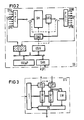
- the coupling arrangement GS is shown in more detail in a special embodiment in FIG.
- the centerpiece of this switching arrangement which represents a time stage, is a voice memory SM, on the input side of which a time-division multiplex line for incoming transmission direction SPHI via a series-parallel converter SPC, which is provided by the connection units LTU according to FIG. 1 or to a lesser extent by the central switching network SN0 / SN1 are to be expected.
- a series-parallel converter SPC which is provided by the connection units LTU according to FIG. 1 or to a lesser extent by the central switching network SN0 / SN1 are to be expected.
- time-division multiplex lines SPHO are connected via a parallel-series converter PSC, which are to be thought of as leading to the mentioned connection units LTU or to the central switching network SNO / SN1.
- the coupler control designated by GSC in FIG. 1 is shown in FIG. 2 broken down into a GS / H controller with associated hold memory and a GS / ⁇ P coupler control microprocessor.
- the mentioned control also influences a device CATU, which serves for the damping and possibly code conversion of code representation according to the ⁇ -law into code representation according to the A-law or vice versa, and a conference device CONU.
- the actual test module provided in accordance with the invention is designated STU in FIG. It lies in a line loop formed by the multiplex lines SPHIP and SPHOP, which in the same way as the multiplex lines SPHI and SPHO, on which voice information is transmitted, with the series-parallel converter SPC and the parallel-series converter PSC and thus with the coupling arrangement in Connect.
- the STU test module must therefore have a serial interface for these SPAIP and SPAOP time-division multiplex lines.
- test module STU is located on a bus line B, to which the mentioned parts GS / H and G / ⁇ P of the coupler control as well as a signal multiplexer SMX are connected, via which signaling characters are exchanged with the coordination processor CP.
- the test module STU which is connected to bus B via a parallel interface, is directly influenced by the coupler control via this bus.
- test assembly STU The essential components of the test assembly STU are shown in FIG.
- the test module STU furthermore has an output memory OMEM, from which data can reach the test multiplex line SPHIP in FIG. 1 via a parallel-series converter P / S, and an input memory IMEM, in which data from the test multiplex line SPHOP in FIG. 2 and above a series-parallel converter S / P data can be written.
- the series-parallel converters and parallel-series converters that form the above-mentioned interface are equipped so that a mirror function can be carried out, that is, data read from the OMEM memory can be returned directly to the IMEM memory.
- test module STU has an input data evaluation EW.
- the STU test module can be used to test both normal subscriber connections and conference connections as well as audio overlays in conference connections.
- a self-test of the test module then follows, for which the mirror function mentioned is switched and test data supplied by the switching matrix controller via the processor interface PS is written into the output memory OMEM, read out from there and entered into the input data memory IMEM via the mirror.
- test data are then switched through from the OMEM memory via the coupling arrangement GS and transmitted back to the test module STU via the output-side multiplex line SPHOP. There, they are compared by the input data evaluation module EW with data that came into the memory IMEM in the course of the described mirroring and that represent the target data. In the event of a deviation, a message is sent to the coupler control GS.
- the concept according to the invention means that the control tasks have been shifted from the group control to the periphery, and the coupler control GSC is also largely relieved. It is therefore possible to test the voice channels on a much larger scale, and error detection is also carried out very quickly. Because on the multiplex line 32 time slots are available, the voice memory SM or its hold memory GS / H can be checked over their entire memory areas and not just on a random basis.
Landscapes
- Engineering & Computer Science (AREA)
- Computer Networks & Wireless Communication (AREA)
- Monitoring And Testing Of Exchanges (AREA)
- Use Of Switch Circuits For Exchanges And Methods Of Control Of Multiplex Exchanges (AREA)
- Structure Of Telephone Exchanges (AREA)
- Exchange Systems With Centralized Control (AREA)
Abstract
Description
- Die Erfindung betrifft eine Schaltungsanordnung zur Prüfung der Sprechwegedurchschaltung einer Koppelanordnung einer digitalen Multiplex-Vermittlungsstelle, die Bestandteil einer Anschlußgruppe dieser Vermittlungsstelle für den Anschluß von Teilnehmeranschluß- und/oder Verbindungsleitungen ist, wobei diese Anschlußgruppe unter dem Steuereinfluß einer mit der Zentralsteuerung der Vermittlungsstelle kommunizierenden Gruppensteuerung steht, die die Koppelanordnung im Zusammenwirken mit einer Kopplersteuerung und die übrigen Bestandteile der Anschlußgruppe direkt beeinflußt.
- Bei einer bekannten Zeitmultiplex-Vermittlungsstelle mit der obengenannten Anschlußstruktur ("EWSD Anschlußgruppen LTG"; Siemens Druckschrift A 30 808-X 2720-X-1-18) sind sämtliche Baueinheiten einer solchen Anschlußgruppe mit der Gruppensteuerung über eine Zeitmultiplexleitung verbunden. Die auf dieser Zeitmultiplexleitung gebildeten 32 Zeitkanäle sind den einzelnen Baueinheiten zugeordnet, die demnach jeweils nur über diese Zeitkanäle mit der Gruppensteuerung in Signalaustausch treten können. Außerdem sind auf dieser Zeitmultiplexleitung zusätzliche Prüfkanäle gebildet, auf denen über einen gesonderten Anschluß der Koppelanordnung die vermittlungstechnischen Funktionen derselben geprüft werden. Es werden in diesem Zusammenhang durch die Koppelanordnung Prüfverbindungen durchgeschaltet und bestimmte Prüfbitmuster gesendet und empfangsseitig auf Fehlerfreiheit überprüft.
- Ein wesentlicher Nachteil dieses Prüfkonzepts liegt in der großen dynamischen Belastung der die genannten Prozeduren steuernden Gruppensteuerung mit der Folge, daß diese Prüfungen nur selten durchgeführt werden können und damit es bis zu einer Fehler erkennung relativ lange dauern kann. Außerdem stößt die Fehlerlokalisierung auf große Schwierigkeiten.
- Die Aufgabe der Erfindung besteht nun darin, ein diesbezüglich günstigeres Konzept anzugeben.
- Die Lösung dieser Aufgabe erfolgt mit einer Schaltungsanordnung der eingangs genannten Art, die durch die im Patentanspruch 1 angegebenen Merkmale gekennzeichnet ist.
- Nachstehend wird die Erfindung anhand eines Ausführungsbeispiels unter Bezugnahme auf eine Zeichnung näher erläutert. In der Zeichnung zeigen:
- FIG 1 die Struktur einer digitalen Zeitmultiplex-Fernmeldevermittlungsstelle, deren Bestandteil die erfindungsgemäße Schaltungsanordnung ist.
- FIG 2 eine Koppleranordnung einer solchen Fernmeldevermittlungsstelle zusammen mit der erfindungsgemäß vorgesehenen Prüfbaugruppe.
- FIG 3 die Prüfbaugruppe in mehr ins einzelne gehender Darstellung.
- Die in FIG 1 dargestellte digitale Zeitmultiplex-Vermittlungsstelle besteht aus einer Reihe von Anschlußgruppen LTG1 bis LTGn, aus einem gedoppelten Koppelnetz SN0/SN1 sowie aus einem Koordinationsprozessor.
- Die Anschlußgruppen LTG1 bis LTGn dienen dem Anschluß von Teilnehmeranschluß- und/oder Verbindungsleitungen PCMe0 bis PCMe11. Sie weisen Anschlußeinheiten LTUl bis LTUx auf, die ihrerseits die hier nicht dargestellten Teilnehmersätze oder Leitungssätze enthalten. Weiterer Bestandteil der Anschlußgruppen sind eine Koppelanordnung GS mit eigener Kopplersteuerung GSC, die eine Vermittlung zwischen den auf den erwähnten Anschlußleitungen gebildeten Zeitkanälen und dem zentralen Koppelnetz SN0/SN1 bewirkt. Ferner enthalten die Anschlußgruppen eine Signaleinheit SU sowie eine Schnittstelleneinheit LIU, die die Schnittstelle zwischen der Anschlußgruppe und dem Koppelnetz SN0/SN1 darstellt. Die Bestandteile der Anschlußgruppen stehen jeweils unter dem Steuereinfluß einer Gruppensteuerung GP, die ihrerseits über das zentrale Koppelnetz mit dem erwähnten Koordinationsprozessor CP also der Zentralsteuerung der Vermittlungsstelle kommuniziert.
- In der FIG 2 ist die Koppelanordnung GS in spezieller Ausführungsform mehr ins einzelne gehend dargestellt.
- Kernstück dieser Koppelanordnung, die eine Zeitstufe darstellt, ist ein Sprachspeicher SM, an den eingangsseitig über einen Serien-Parallel-Wandler SPC Zeitmultiplexleitungen für kommende Übertragungsrichtung SPHI, die von den Anschlußeinheiten LTU gemäß FIG 1 bzw. zu einem geringeren Teil von dem zentralen Koppelfeld SN0/SN1 kommend zu denken sind. Ausgangsseitig sind über einen Parallel-Serien-Wandler PSC Zeitmultiplexleitungen SPHO angeschlossen, die zu den erwähnten Anschlußeinheiten LTU bzw. zum zentralen Koppelfeld SNO/SN1 hinführend zu denken sind.
- Die in FIG 1 mit GSC bezeichnete Kopplersteuerung ist in FIG 2 in eine Steuerung GS/H mit zugehörigem Haltespeicher und in einen Kopplersteuerungsmikroprozessor GS/µP gegliedert dargestellt.
- Die genannte Steuerung beeinflußt außer dem Sprachspeicher ferner noch eine Einrichtung CATU, die der Dämpfung und ggfs. Codekonvertierung von Codedarstellung gemäß dem µ-Gesetz in Codedarstellung gemäß dem A-Gesetz bzw. umgekehrt dient, sowie eine Konferenzeinrichtung CONU.
- Die eigentliche gemäß der Erfindung vorgesehene Prüfbaugruppe ist in FIG 2 mit STU bezeichnet. Sie liegt in einer Leitungs schleife die von Multiplexleitungen SPHIP und SPHOP gebildet wird, die in gleicher Weise wie die erwähnten Multiplexleitungen SPHI und SPHO, auf denen Sprachinformationen übertragen werden, mit dem Serien-Parallel-Wandler SPC und dem Parallel-Serien-Wandler PSC und damit mit der Koppelanordnung in Verbindung stehen. Die Prüfbaugruppe STU hat damit zu diesen Zeitmultiplexleitung SPAIP und SPAOP hin eine serielle Schnittstelle aufzuweisen.
- Wie die FIG 2 ferner zeigt, liegt die Prüfbaugruppe STU an einer Busleitung B, an der außerdem die erwähnten Teile GS/H und G/µP der Kopplersteuerung sowie ein Signalmultiplexer SMX angeschlossen sind, über den ein Signalisierungszeichenaustausch mit dem Koordinationsprozessor CP erfolgt. Die Prüfbaugruppe STU, die an den Bus B über eine Parallelschnittstelle angeschlossen ist, wird über diesen Bus von der Kopplersteuerung direkt beeinflußt.
- In der FIG 3 sind die wesentlichen Bestandteile der Prüfbaugrppe STU dargestellt.
- Es sind dies die schon erwähnte Parallelschnittstelle PS zum Bus B bzw. dem Mikroprozessor G/µP der Kopplersteuerung. Es sind dies ferner eine interne Steuerung St, deren wesentliche Aufgabe die Festlegung der Sende- uind Empfangszeitpunkte im Zusammenhang mit der Durchführung von Prüfungen ist, die von der Kopplersteuerung veranlaßt werden, sowie die Steuerung von im Zuge der Prüfung durchgeführten Soll/Ist-Vergleichen.
- Die Prüfbaugruppe STU weist ferner einen Ausgabespeicher OMEM auf, von dem aus Daten über einen Parallel-Serien-Wandler P/S an die Prüfmultiplexleitung SPHIP in FIG 1 gelangen können, sowie einen Eingabespeicher IMEM, in den von der Prüfmultiplexleitung SPHOP in FIG 2 und über einen Serien-Parallel-Wandler S/P Daten eingeschrieben werden. Die die obenerwähnte Schnittstelle bildenden Serien-Parallelwandler und Parallel-Serienwandler sind so ausgestattet, daß eine Spiegelfunktion ausgeführt werden kann, also aus dem Speicher OMEM ausgelesene Daten direkt wieder zurück in den Speicher IMEM gelangen können.
- Schließlich weist die Prüfbaugruppe STU eine Eingabendatenbewertung EW auf.
- Mit der Prüfbaugruppe STU können sowohl normale Teilnehmerverbindungen als auch Konferenzverbindungen sowie Toneinblendungen in Konferenzverbindungen geprüft werden.
- Zu Beginn einer Prüfung wird daher zunächst die Art der Prüfung festgelegt. Es folgt dann ein Eigentest der Prüfbaugruppe, wozu die erwähnte Spiegelfunktion geschaltet wird und von der Koppelfeldsteuerung über die Prozessorschnittstelle PS gelieferte Prüfdaten in den Ausgabespeicher OMEM eingeschrieben, von dort ausgelesen und über den Spiegel in den Eingabedatenspeicher IMEM eingetragen werden.
- Nach Auflösen der Spiegelfunktion und Festlegung der Sende- und Empfangszeitlagen werden dann die Prüfdaten vom Speicher OMEM aus über die Koppelanordnung GS durchgeschaltet und über die ausgangsseitige Multiplexleitung SPHOP wieder an die Prüfbaugruppe STU zurückübertragen. Dort werden sie durch die Eingabedatenbewertungsbaugruppe EW mit im Zuge der erläuterten Spiegelung in den Speicher IMEM gelangten Daten, die die Soll-Daten darstellen, verglichen. Im Falle einer Abweichung erfolgt eine Meldung an die Kopplersteuerung GS.
- Durch das erfindungsgemäße Konzept sind also im Gegensatz zu den bisherigen Verhältnissen die Steuerungsaufgaben von der Gruppensteuerung auf die Peripherie verlagert, wobei auch die Kopplersteuerung GSC weitgehend entlastet ist. Es sind daher Tests der Sprachkanäle in weitaus größerem Umfang möglich, wobei außerdem die Fehlererkennung sehr schnell erfolgt. Da auf der Multiplex leitung 32 Zeitschlitze zur Verfügung stehen, können der Sprachspeicher SM bzw. dessen Haltespeicher GS/H über ihre ganzen Speicherbereiche und nicht nur stichprobenartig geprüft werden.
Claims (4)
gekennzeichnet durch folgende Merkmale:
dadadurch gekennzeichnet,
daß die Prüfbaugruppe (STU) folgende Bestandteile aufweist:
dadurch gekennzeichnet,
daß die Schnittstelle der Prüfbaugruppe (STU) zur Prüfmultiplexleitung (SPHIP, SPHOP) eine serielle Schnittelle ist.
dadurch gekennzeichnet,
daß die Schnittstelle der Prüfbaugruppe zur Kopplersteuerung eine parallele Schnittstelle (PS) ist.
Applications Claiming Priority (2)
| Application Number | Priority Date | Filing Date | Title |
|---|---|---|---|
| DE3915927 | 1989-05-16 | ||
| DE3915927A DE3915927A1 (de) | 1989-05-16 | 1989-05-16 | Schaltungsanordnung zur pruefung der sprechwegedurchschaltugn einer koppelanordnung |
Publications (3)
| Publication Number | Publication Date |
|---|---|
| EP0398041A2 true EP0398041A2 (de) | 1990-11-22 |
| EP0398041A3 EP0398041A3 (de) | 1992-08-19 |
| EP0398041B1 EP0398041B1 (de) | 1995-12-27 |
Family
ID=6380747
Family Applications (1)
| Application Number | Title | Priority Date | Filing Date |
|---|---|---|---|
| EP90107681A Expired - Lifetime EP0398041B1 (de) | 1989-05-16 | 1990-04-23 | Vermittlungsstelle mit einer Schaltungsanordnung zur Prüfung der Sprechwegedurchschaltung einer Koppelanordnung |
Country Status (5)
| Country | Link |
|---|---|
| EP (1) | EP0398041B1 (de) |
| AT (1) | ATE132314T1 (de) |
| DE (2) | DE3915927A1 (de) |
| ES (1) | ES2081316T4 (de) |
| GR (1) | GR3018555T3 (de) |
Cited By (2)
| Publication number | Priority date | Publication date | Assignee | Title |
|---|---|---|---|---|
| EP0610672A3 (en) * | 1993-01-13 | 1995-11-29 | Nec Corp | Time division switch. |
| EP0516079A3 (en) * | 1991-05-27 | 1996-10-30 | Fujitsu Ltd | Digital signal transmission system having monitor equipment |
Families Citing this family (2)
| Publication number | Priority date | Publication date | Assignee | Title |
|---|---|---|---|---|
| JP2621688B2 (ja) * | 1991-05-13 | 1997-06-18 | 株式会社船井電機研究所 | 有線又は無線受信機 |
| DE4317367C1 (de) * | 1993-05-25 | 1994-08-25 | Siemens Ag | Koppelnetz für eine digitale Zeitmultiplex-Fernsprechvermittlungsstelle |
Family Cites Families (4)
| Publication number | Priority date | Publication date | Assignee | Title |
|---|---|---|---|---|
| US4156110A (en) * | 1976-03-05 | 1979-05-22 | Trw Inc. | Data verifier |
| DE2905426C2 (de) * | 1979-02-13 | 1986-07-10 | Siemens AG, 1000 Berlin und 8000 München | Verfahren zur Prüfung der Funktionsfähigkeit von im Zusammenhang mit der Herstellung von Konferenzverbindungen ausgenutzten Sprachspeichern und übrigen Einrichtungen einer PCM-Zeitmultiplex-Vermittlungseinheit |
| JPS6148266A (ja) * | 1984-08-15 | 1986-03-08 | Fujitsu Ltd | 時分割多重回線折返試験方法 |
| ES2088399T3 (es) * | 1989-09-29 | 1996-08-16 | Siemens Ag | Disposicion de circuito para la verificacion de partes de una central digital de conmutacion de telecomunicaciones multiplex por division de tiempo, especialmente una central de conmutacion telefonica. |
-
1989
- 1989-05-16 DE DE3915927A patent/DE3915927A1/de not_active Withdrawn
-
1990
- 1990-04-23 AT AT90107681T patent/ATE132314T1/de not_active IP Right Cessation
- 1990-04-23 ES ES90107681T patent/ES2081316T4/es not_active Expired - Lifetime
- 1990-04-23 DE DE59009995T patent/DE59009995D1/de not_active Expired - Fee Related
- 1990-04-23 EP EP90107681A patent/EP0398041B1/de not_active Expired - Lifetime
-
1995
- 1995-12-28 GR GR950403658T patent/GR3018555T3/el unknown
Cited By (2)
| Publication number | Priority date | Publication date | Assignee | Title |
|---|---|---|---|---|
| EP0516079A3 (en) * | 1991-05-27 | 1996-10-30 | Fujitsu Ltd | Digital signal transmission system having monitor equipment |
| EP0610672A3 (en) * | 1993-01-13 | 1995-11-29 | Nec Corp | Time division switch. |
Also Published As
| Publication number | Publication date |
|---|---|
| ES2081316T4 (es) | 1997-04-01 |
| DE3915927A1 (de) | 1991-01-31 |
| EP0398041A3 (de) | 1992-08-19 |
| EP0398041B1 (de) | 1995-12-27 |
| DE59009995D1 (de) | 1996-02-08 |
| GR3018555T3 (en) | 1996-03-31 |
| ATE132314T1 (de) | 1996-01-15 |
| ES2081316T3 (es) | 1996-03-01 |
Similar Documents
| Publication | Publication Date | Title |
|---|---|---|
| EP0111832B1 (de) | Schaltungsanordnung zur Fehlerortung bei einem digitalen Fernmelde-Teilnehmeranschluss | |
| EP0448734B1 (de) | Schaltungsanordnung für die Routineprüfung einer Schnittstelle zwischen Anschlussgruppen und dem Koppelnetz eines PCM-Fernmeldevermittlungssystems | |
| DE4120065A1 (de) | Terminaladapter-verbindungssystem | |
| EP0398041B1 (de) | Vermittlungsstelle mit einer Schaltungsanordnung zur Prüfung der Sprechwegedurchschaltung einer Koppelanordnung | |
| DE19506961C1 (de) | Verfahren zum Anschluß von Access-Networks mit V5.2-Schnittstellen an Kommunikationssysteme mit nichtredundanten peripheren Einrichtungen | |
| DE2304923C3 (de) | Verfahren zur Prüfung von Vierdrahtverbindungen zwischen zwei miteinander zu verbindenden Schaltstellen eines Fernmeldenetze? | |
| EP0163288A1 (de) | Verfahren zur Durchschalteprüfung eines Raummultiplex-Koppelnetzes | |
| DE3035276C2 (de) | Schaltungsanordnung zur Verbindung von Informationsquellen für Fernmelde-, insbesondere Fernsprechvermittlungsanlagen | |
| DE3403454C2 (de) | ||
| EP0613282B1 (de) | Schaltungsanordnung zur Herstellung von Konferenzverbindungen in einer digitalen Zeitmultiplex-Fernmeldevermittlungsstelle | |
| EP0590182B1 (de) | Verfahren zum Betrieb der Zeitstufenelemente bzw. kombinierten Zeit-Raumstufenelemente einer Koppelanordnung einer digitalen Zeitmultiplex Fernmeldevermittlungsstelle | |
| DE3246051C2 (de) | ||
| EP0598931B1 (de) | Verfahren zur Überwachung bestehender Fernsprechverbindungen, insbesondere permanent geschalteter Fernsprechverbindungen | |
| DE3405011C1 (de) | Schaltungsanordnung zum Betreiben von zweiadrigen, digitalen Anschluß- und/oder Verbindungsleitungen an einer Fernmeldevermittlungsanlage | |
| EP0387667A2 (de) | Schaltungsanordung für zentralgesteuerte Zeitmultiplex-Fernsprechvermittlungsanlagen mit zentralem Koppelfeld und dezentralen Anschlussgruppen | |
| EP0280895B1 (de) | Digitale Schnittstelle zwischen wenigstens zwei Teilnehmeranschlussschaltungseinheiten und einer Verarbeitungseinheit | |
| DE19814435B4 (de) | Kommunikationssystem mit Baugruppenträgereinheit | |
| DE2945032C2 (de) | Verfahren zur Prüfung der Sendeeinrichtung für Wahlinformationen von Verbindungsleitungs- Übertragungen | |
| EP0624022B1 (de) | Anordnung zur Sprechwegeprüfung in einem Koppelnetz einer digitalen Zeitmultiplex-Fernsprechvermittlungsstelle | |
| DE3713933C2 (de) | Digitales Übertragungssystem | |
| EP1118202A1 (de) | Verfahren zum prüfen von teilnehmeranschlussleitungen | |
| EP0606582B1 (de) | Zentralgesteuerte digitale Zeitmultiplex-Fernsprechvermittlungsanlage | |
| CH681410A5 (de) | ||
| DE10030122A1 (de) | Einrichtung zum Verbinden einer Datenverarbeitungseinrichtung mit einer Telekommunikationsanlage | |
| DE2935694A1 (de) | Schaltungsanordnung zur herstellung von sonderverbindungen, insbesondere von pruefverbindungen in einer rechnergesteuerten nachrichtenvermittlungsanlage, insbesondere in einer programmgesteuerten fernsprechwaehlanlage |
Legal Events
| Date | Code | Title | Description |
|---|---|---|---|
| PUAI | Public reference made under article 153(3) epc to a published international application that has entered the european phase |
Free format text: ORIGINAL CODE: 0009012 |
|
| AK | Designated contracting states |
Kind code of ref document: A2 Designated state(s): AT BE CH DE ES FR GB GR IT LI NL SE |
|
| 17P | Request for examination filed |
Effective date: 19901205 |
|
| PUAL | Search report despatched |
Free format text: ORIGINAL CODE: 0009013 |
|
| AK | Designated contracting states |
Kind code of ref document: A3 Designated state(s): AT BE CH DE ES FR GB GR IT LI NL SE |
|
| 17Q | First examination report despatched |
Effective date: 19931129 |
|
| GRAA | (expected) grant |
Free format text: ORIGINAL CODE: 0009210 |
|
| AK | Designated contracting states |
Kind code of ref document: B1 Designated state(s): AT BE CH DE ES FR GB GR IT LI NL SE |
|
| REF | Corresponds to: |
Ref document number: 132314 Country of ref document: AT Date of ref document: 19960115 Kind code of ref document: T |
|
| REF | Corresponds to: |
Ref document number: 59009995 Country of ref document: DE Date of ref document: 19960208 |
|
| REG | Reference to a national code |
Ref country code: CH Ref legal event code: NV Representative=s name: SIEMENS-ALBIS AKTIENGESELLSCHAFT Ref country code: GR Ref legal event code: FG4A Free format text: 3018555 |
|
| REG | Reference to a national code |
Ref country code: ES Ref legal event code: FG2A Ref document number: 2081316 Country of ref document: ES Kind code of ref document: T3 |
|
| ITF | It: translation for a ep patent filed | ||
| GBT | Gb: translation of ep patent filed (gb section 77(6)(a)/1977) |
Effective date: 19960304 |
|
| ET | Fr: translation filed | ||
| PLBE | No opposition filed within time limit |
Free format text: ORIGINAL CODE: 0009261 |
|
| STAA | Information on the status of an ep patent application or granted ep patent |
Free format text: STATUS: NO OPPOSITION FILED WITHIN TIME LIMIT |
|
| 26N | No opposition filed | ||
| K2C3 | Correction of patent specification (complete document) published |
Effective date: 19951227 |
|
| PGFP | Annual fee paid to national office [announced via postgrant information from national office to epo] |
Ref country code: CH Payment date: 19980709 Year of fee payment: 9 |
|
| PGFP | Annual fee paid to national office [announced via postgrant information from national office to epo] |
Ref country code: GR Payment date: 19990323 Year of fee payment: 10 |
|
| PGFP | Annual fee paid to national office [announced via postgrant information from national office to epo] |
Ref country code: AT Payment date: 19990331 Year of fee payment: 10 |
|
| PGFP | Annual fee paid to national office [announced via postgrant information from national office to epo] |
Ref country code: GB Payment date: 19990413 Year of fee payment: 10 |
|
| PGFP | Annual fee paid to national office [announced via postgrant information from national office to epo] |
Ref country code: BE Payment date: 19990419 Year of fee payment: 10 |
|
| PGFP | Annual fee paid to national office [announced via postgrant information from national office to epo] |
Ref country code: ES Payment date: 19990420 Year of fee payment: 10 |
|
| PGFP | Annual fee paid to national office [announced via postgrant information from national office to epo] |
Ref country code: NL Payment date: 19990427 Year of fee payment: 10 |
|
| PG25 | Lapsed in a contracting state [announced via postgrant information from national office to epo] |
Ref country code: LI Free format text: LAPSE BECAUSE OF NON-PAYMENT OF DUE FEES Effective date: 19990430 Ref country code: CH Free format text: LAPSE BECAUSE OF NON-PAYMENT OF DUE FEES Effective date: 19990430 |
|
| REG | Reference to a national code |
Ref country code: CH Ref legal event code: PL |
|
| PG25 | Lapsed in a contracting state [announced via postgrant information from national office to epo] |
Ref country code: GB Free format text: LAPSE BECAUSE OF NON-PAYMENT OF DUE FEES Effective date: 20000423 Ref country code: AT Free format text: LAPSE BECAUSE OF NON-PAYMENT OF DUE FEES Effective date: 20000423 |
|
| PG25 | Lapsed in a contracting state [announced via postgrant information from national office to epo] |
Ref country code: ES Free format text: THE PATENT HAS BEEN ANNULLED BY A DECISION OF A NATIONAL AUTHORITY Effective date: 20000424 |
|
| PG25 | Lapsed in a contracting state [announced via postgrant information from national office to epo] |
Ref country code: GR Free format text: LAPSE BECAUSE OF NON-PAYMENT OF DUE FEES Effective date: 20000430 Ref country code: BE Free format text: LAPSE BECAUSE OF NON-PAYMENT OF DUE FEES Effective date: 20000430 |
|
| BERE | Be: lapsed |
Owner name: SIEMENS A.G. Effective date: 20000430 |
|
| PG25 | Lapsed in a contracting state [announced via postgrant information from national office to epo] |
Ref country code: NL Free format text: LAPSE BECAUSE OF NON-PAYMENT OF DUE FEES Effective date: 20001101 |
|
| GBPC | Gb: european patent ceased through non-payment of renewal fee |
Effective date: 20000423 |
|
| NLV4 | Nl: lapsed or anulled due to non-payment of the annual fee |
Effective date: 20001101 |
|
| PGFP | Annual fee paid to national office [announced via postgrant information from national office to epo] |
Ref country code: SE Payment date: 20020423 Year of fee payment: 13 |
|
| PGFP | Annual fee paid to national office [announced via postgrant information from national office to epo] |
Ref country code: FR Payment date: 20020430 Year of fee payment: 13 |
|
| REG | Reference to a national code |
Ref country code: ES Ref legal event code: FD2A Effective date: 20020304 |
|
| PGFP | Annual fee paid to national office [announced via postgrant information from national office to epo] |
Ref country code: DE Payment date: 20020618 Year of fee payment: 13 |
|
| PG25 | Lapsed in a contracting state [announced via postgrant information from national office to epo] |
Ref country code: SE Free format text: LAPSE BECAUSE OF NON-PAYMENT OF DUE FEES Effective date: 20030424 |
|
| PG25 | Lapsed in a contracting state [announced via postgrant information from national office to epo] |
Ref country code: DE Free format text: LAPSE BECAUSE OF NON-PAYMENT OF DUE FEES Effective date: 20031101 |
|
| EUG | Se: european patent has lapsed | ||
| PG25 | Lapsed in a contracting state [announced via postgrant information from national office to epo] |
Ref country code: FR Free format text: LAPSE BECAUSE OF NON-PAYMENT OF DUE FEES Effective date: 20031231 |
|
| REG | Reference to a national code |
Ref country code: FR Ref legal event code: ST |
|
| PG25 | Lapsed in a contracting state [announced via postgrant information from national office to epo] |
Ref country code: IT Free format text: LAPSE BECAUSE OF NON-PAYMENT OF DUE FEES;WARNING: LAPSES OF ITALIAN PATENTS WITH EFFECTIVE DATE BEFORE 2007 MAY HAVE OCCURRED AT ANY TIME BEFORE 2007. THE CORRECT EFFECTIVE DATE MAY BE DIFFERENT FROM THE ONE RECORDED. Effective date: 20050423 |