EP0398050A2 - Régulateur de pression - Google Patents
Régulateur de pression Download PDFInfo
- Publication number
- EP0398050A2 EP0398050A2 EP90107937A EP90107937A EP0398050A2 EP 0398050 A2 EP0398050 A2 EP 0398050A2 EP 90107937 A EP90107937 A EP 90107937A EP 90107937 A EP90107937 A EP 90107937A EP 0398050 A2 EP0398050 A2 EP 0398050A2
- Authority
- EP
- European Patent Office
- Prior art keywords
- diaphragm
- pressure regulator
- pressure
- set forth
- gas
- Prior art date
- Legal status (The legal status is an assumption and is not a legal conclusion. Google has not performed a legal analysis and makes no representation as to the accuracy of the status listed.)
- Withdrawn
Links
- 239000000463 material Substances 0.000 claims abstract description 10
- 238000006073 displacement reaction Methods 0.000 claims abstract description 5
- 230000008878 coupling Effects 0.000 claims description 27
- 238000010168 coupling process Methods 0.000 claims description 27
- 238000005859 coupling reaction Methods 0.000 claims description 27
- 239000012530 fluid Substances 0.000 claims description 14
- 238000010276 construction Methods 0.000 claims description 9
- 238000004891 communication Methods 0.000 claims description 6
- 238000013022 venting Methods 0.000 claims 1
- 239000012812 sealant material Substances 0.000 abstract description 2
- 238000004519 manufacturing process Methods 0.000 description 4
- 230000000712 assembly Effects 0.000 description 2
- 238000000429 assembly Methods 0.000 description 2
- 230000001105 regulatory effect Effects 0.000 description 2
- 230000008901 benefit Effects 0.000 description 1
- 238000006243 chemical reaction Methods 0.000 description 1
- 230000003247 decreasing effect Effects 0.000 description 1
- 230000001627 detrimental effect Effects 0.000 description 1
- 230000000694 effects Effects 0.000 description 1
- 238000004880 explosion Methods 0.000 description 1
- 230000006872 improvement Effects 0.000 description 1
- 230000013011 mating Effects 0.000 description 1
- 238000007789 sealing Methods 0.000 description 1
- 238000005549 size reduction Methods 0.000 description 1
- XLYOFNOQVPJJNP-UHFFFAOYSA-N water Substances O XLYOFNOQVPJJNP-UHFFFAOYSA-N 0.000 description 1
Images

Classifications
-
- G—PHYSICS
- G05—CONTROLLING; REGULATING
- G05D—SYSTEMS FOR CONTROLLING OR REGULATING NON-ELECTRIC VARIABLES
- G05D16/00—Control of fluid pressure
- G05D16/04—Control of fluid pressure without auxiliary power
- G05D16/06—Control of fluid pressure without auxiliary power the sensing element being a flexible membrane, yielding to pressure, e.g. diaphragm, bellows, capsule
- G05D16/063—Control of fluid pressure without auxiliary power the sensing element being a flexible membrane, yielding to pressure, e.g. diaphragm, bellows, capsule the sensing element being a membrane
- G05D16/0675—Control of fluid pressure without auxiliary power the sensing element being a flexible membrane, yielding to pressure, e.g. diaphragm, bellows, capsule the sensing element being a membrane the membrane acting on the obturator through a lever
- G05D16/0683—Control of fluid pressure without auxiliary power the sensing element being a flexible membrane, yielding to pressure, e.g. diaphragm, bellows, capsule the sensing element being a membrane the membrane acting on the obturator through a lever using a spring-loaded membrane
Definitions
- the present invention relates to diaphragm actuated pressure regulators and more particularly to diaphragm actuated pressure regulators having a compact construction.
- Diaphragm actuated pressure regulators generally operate by placing a flexible diaphragm in fluid communication with an area the pressure of which is maintained to be equivalent to the fluid line pressure being regulated. As the pressure in this area fluctuates, the diaphragm deflects proportionally. There is typically provided a counteracting spring force to regulate the diaphragm so that it deflects in a predictable fashion.
- Another advantage to having a large diaphragm is that less pressure needs to be exerted on the diaphragm to generate a sufficient force on the linkage and valve to lock up the regulator so that all fluid flow to the fluid line is stopped.
- a typical regulator of this type will have a diaphragm of 26 square inches and a lever ratio of 3:1. Accordingly, when 1 psi. of outlet pressure is exerted on this diaphragm a resulting lock-up force of 78 pounds is generated to close off the valve.
- known diaphragm actuated pressure regulators often use a diaphragm which is large enough so that with a typical lever ratio they will afford the desired pressure control. Regulators using these large diaphragms, however, are relatively expensive to manufacture and obtrusive when installed.
- Known diaphragm actuated pressure regulators have been able to reduce the size of the diaphragm used by providing diaphragms with changeable surface areas and complicated linkages. By so doing, known regulators have been able to provide a longer deflection stroke with less material deformation than conventional pressure regulators having smaller diaphragms with longer strokes.
- One such regulator is described in U.S. Patent No. 2,651,328 to C.B. Gamble.
- the device of the present invention which is a diaphragm actuated pressure regulator having a relatively small diaphragm which is capable of increasing its surface area when in the upper portion of its deflection stroke and a lever ratio which is greater than the lever ratio afforded by known pressure regulators.
- This large lever ratio is achieved by moving a fulcrum pin about which a lever of the regulator rotates into the throat of the regulator.
- the pressure regulator is provided with a one piece curved lever arm and a fulcrum pin positioned in the throat area of the regulator which can provide a lever ratio of as much as twice that of a pressure regulator having a standard straight lever arm and a fulcrum pin positioned in the regulator's lower case.
- This allows the current pressure regulator to generate a valve closing force that is substantially greater than the valve closing force generated by known pressure regulators.
- the pressure regulator of the present invention can operate with a much smaller diaphragm. The result of having a greater lever ratio, however, is that the diaphragm will be forced to deflect proportionally farther than a diaphragm being used in an assembly with a standard lever ratio.
- a molded diaphragm having a contoured profile so that there is reduced deformation of the diaphragm material as the upper portion of the diaphragm's deflection stroke is approached.
- the diaphragm is designed to have an effective surface area against which the pressure in the abutting area acts and contoured portions which behave in a hinging fashion. In this manner, the diaphragm will have a substantially constant effective surface area due to the ability of the contoured portions of the diaphragm to absorb the effects of the diaphragm's deflection.
- a diaphragm is provided with a useful deflection stroke of up to twice as long as the deflection stroke of a flat diaphragm.
- the present invention is able to provide a pressure regulator having a smaller diaphragm case than known pressure regulators while providing the same performance characteristics. Because of this size reduction and simplified construction, the pressure regulator in accordance with the present invention will have a significantly lower material cost than known pressure regulators and operate more precisely.
- the pressure regulator of the present invention is provided with a pressure responsive diaphragm in fluid communication with a fluid line receiving pressurized gas from a source and delivering the gas for use.
- the diaphragm provided is designed to have a relatively constant effective surface area so that operation in the upper portion of the diaphragm's deflection stroke can be utilized.
- the pressure regulator of the present invention includes a curved lever arm for transmitting the deflection of the diaphragm to a valve pad to restrict the amount of gas that can flow from the source line to the delivery line.
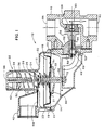
- FIG. 1 there is shown a pressure regulator which will be generally referred to by reference number 10.
- the outer dimensions of the regulator 10 are defined by a cover assembly 12 and a lower case 14 which are secured together and within which the diaphragm assembly of the regulator 10 is contained.
- the cover assembly 12 and the lower case 14 are formed with equivalent circumferential portions 19 and 21 respectively so that the two components can be affixed together to define an inner chamber of the regulator.
- the diaphragm circumference is molded to form an O-ring 20 which fits within a groove defined by the circumferential portions 19 and 21.
- the pressure regulator of the present invention is constructed more simply than known pressure regulators which require a separate gasket or sealant material to be applied at the junction of the upper and lower portions of the regulator.
- the present invention provides a one piece diaphragm 18 which is self sealing by means of the O-ring 20 being sandwiched between the circumferential portion 19 of the cover assembly and the circumferential portion 21 of the lower case 14.
- a diaphragm pan 22 forms the diaphragm 18 to define an effective surface area against which pressure forces in the area below the diaphragm 18 will act. These pressure forces will tend to urge the diaphragm 18 to deflect upward. Urging the diaphragm 18 in opposition to these pressure forces is a main spring 32 which is buttressed against an adjusting ferrule 34. By selecting the proper spring force for the main spring 32 and positioning the adjusting ferrule 34 the deflection of the diaphragm 18 in relation to the pressure forces in the below area can be controlled.
- the position of the adjusting ferrule 34 is adjustable. As shown in FIG. 1, the adjusting ferrule 34 is positioned within a cylindrical portion 35 of the cover assembly 14 the interior walls 36 of which are threaded. The adjusting ferrule 34, therefore, is reciprocally threaded so that it can be positioned anywhere along the length of the cylindrical portion 35. In this manner, the force exerted by the main spring 32 can be altered by altering the range within which the main spring 32 is forced to retract.
- the diaphragm 18 is also provided with a circumferential corrugation 23 about its outer perimeter within the cover assembly 14.
- This corrugation 23 allows the diaphragm 18 to deflect toward the adjusting ferrule 34 without having to undergo material deformation which would result in an increased opposition to deflection as the diaphragm 18 approached the upper region of its deflection stroke.
- the effective surface area of the diaphragm 18 against which the pressure forces in the lower area will act will remain substantially constant throughout the entire deflection stroke of the diaphragm 18.
- a diaphragm coupling 30 projecting through the center of the diaphragm pan 22 is a diaphragm coupling 30 which serves at least two functions.
- the diaphragm coupling 30 acts as a relief valve when the pressure in the area below the diaphragm 18 exceeds a predetermined level.
- the diaphragm coupling 30 acts as a means by which the deflection of the diaphragm 18 is transmitted to a lever arm 48 and ultimately to a valve pad 56 which restricts the flow of gas through the regulator.
- the diaphragm coupling 30 acts as a relief valve in conjunction with a cover cap 38, a coupling stop 40, a relief spring 24, a spring retainer 26, a retainer screw 28, and the diaphragm pan 22.
- the diaphragm coupling 30 is provided however, with a lower apron 33 which forms a seal 31 against the diaphragm 18 and prevents the relief spring 24 from pulling the diaphragm coupling 30 through the diaphragm pan 22.
- the seal 31 also prevent gas from escaping from the area below the diaphragm 18 during normal operation.
- the diaphragm 18 will deflect to a greater extent until eventually the retainer screw 28 comes into contact with the coupling stop 40. As the diaphragm 22 deflects past this point, the relief spring 24 will be further compressed between the diaphragm pan 22 and the relief spring retainer 26 and the lower apron 33 of the diaphragm coupling 30 will become separated from the diaphragm 18. As a result, the seal 31 will be broken and gas will be allowed to pass from the area below the diaphragm 18 through the diaphragm 18 and the diaphragm pan 22. The increased gas pressure above the diaphragm 18 will urge a relief valve open and the gas will be able to flow through relief vent 42. This feature of the present invention prevents an unsafe level of pressure from building up below the diaphragm 18 which could result in an explosion.
- a coupling neck 46 On the lower portion of the diaphragm coupling 30 there is provided a coupling neck 46. As shown in FIG. 2, the coupling neck 46 interfits a slot 66 defined by an upper portion 72 of the lever arm 48. Accordingly, as pressure in the area below the diaphragm 18 forces the diaphragm 18 to deflect upward, the diaphragm coupling 30 will prompt the lever arm to pivot about a rocker pin 50. By providing a slotted connection between the diaphragm coupling 30 and the lever arm 48 the linear motion of the diaphragm coupling 30 is simply translated to a rotating motion of the one piece lever arm 48.
- An important inventive feature of the present pressure regulator is the curved lever arm 48 and the positioning of the fulcrum pin 50 in the throat area of the regulator.
- the fulcrum pin 50 is supported in the throat area by a stem guide 52.
- Lever ratio is determined as a function of the horizontal distance between the fulcrum pin 50 and the center of the diaphragm 18 as compared to the vertical distance between the fulcrum pin 50 and the stem 54.
- the fulcrum pin 50 is located in the throat area of the regulator rather than being more centrally located within the lower case as is done in conventional regulators. This construction is further facilitated by the use of the curved moment arm 48. In this manner, the horizontal distance between the fulcrum pin 50 and the center of the diaphragm 18, and thereby the lever ratio, is maximized.
- the lever arm and fulcrum pin arrangement provides a lever ratio of 6:1 as opposed to known pressure regulators which traditionally have lever ratios in the neighborhood of 3:1.
- This increased lever ratio allows the diaphragm 18 to generate a higher valve closing force than it could generate if a small lever ratio were used.
- the pressure regulator 10 of the present invention can be constructed with a diaphragm that is much smaller than would be necessary if a small lever ratio were used. While this increased lever ratio results in the diaphragm 18 having an increased deflection stroke, as discussed above, the diaphragm 18 of the present invention having the corrugation 23 enables it to operate effectively over a broader deflection range than known flat diaphragms.
- the curved lever arm 48, the positioning of the fulcrum pin 50, and the molded diaphragm 18 of the present invention cooperate to provide a pressure regulator that is much more compact than known pressure regulators.
- a stem drive 68 which fits in a slot 69 of a stem 54.
- the stem 54 is capable of linear movement and is supported by a stem guide 52.
- Attached to a distal end of the stem 54 is a valve pad 56 which is able to regulate the flow of gas passing through an inlet 60 in an orifice restriction 58 by moving toward and away from the orifice restriction 58. The farther away from the orifice restriction 58 that the valve pad 54 is positioned, the greater volume of gas that will be able to flow through the inlet 60. In this manner, the valve pad regulates the flow of gas from a gas inlet port 62 to a gas outlet port 64 and thereby the pressure in the gas outlet port 64.
- valve pad 56 will also be urged toward the orifice restriction 58 and the flow rate of gas through the orifice restriction inlet 69 will be limited.
- the pressure of the gas flowing out of the gas outlet port 64 which will be equivalent to the gas pressure in the area below the diaphragm 18, will be prevented from exceeding a predetermined level based on the magnitude of the main spring 32 and the positioning of the adjusting ferrule 34.
- the pressure in the area below the diaphragm 18 will naturally drop. This pressure drop will result in the diaphragm 18 and the diaphragm coupling 30 having a decreased deflection which will cause the lever arm to rotate about the rocker pin 50 in a counter-clockwise direction. This rotation of the lever arm 48 will occasion the stem drive 68 to actuate the stem 54, and thereby the valve pad 54, away from the orifice restriction 58. By so doing, the pressure regulator 10 will allow a higher rate of gas flow through the inlet 60 of the orifice restriction 58 to balance the flow of gas through the gas outlet port.
- pressure regulators of this type are their ability to "lock-up" when there is no demand for gas flow out of the regulator.
- a pressure regulator needs to generate a 75 pound valve closing force at 1 p.s.i. of gas outlet pressure to provide sufficient lock-up.
- An example of a known type of pressure regulator having a lever ratio of 3:1 will need a diaphragm having a surface area of 26 in2 to achieve an acceptable lock-up force at this level of operation.
- a preferred embodiment of the pressure regulator of the present invention has a lever ratio of 6:1.
- Such a lever ratio will enable the pressure regulator 10 to provide comparable performance to known pressure regulators having larger diaphragms while using a diaphragm only having a surface area of from 10 in2 to 14 2.
- the pressure regulator can provide a valve closing force of 75 pounds at 1 p.s.i. of gas outlet pressure.
- the pressure regulator of the present invention is a great improvement over known pressure regulators in that it provides a device having a compact construction while providing comparable performance characteristics to known pressure regulators with relatively large diaphragms.
- lever arm 48 is a single piece rather than a complicated linkage assembly as has been employed by known pressure regulators trying to provide an increased lever ratio.
- the present invention is able to avoid the drawbacks experienced by known pressure regulators using complicated linkages involving a series of straight lever arms connected by pins. These drawbacks include difficulties in manufacturing due to a higher number of components and less precise operation do to the tendency of pin connections to loosen and develop "play.”
- the lever arm 48 forms part of the modular throat assembly of the present invention that is generally referred to by reference number 70 in FIG. 3.
- This modular throat assembly made up of the curved lever arm 48, the rocker pin 50, the stem guide 52, the stem 54, and the valve pad 56 can be assembled apart from the rest of the regulator and easily installed into the lower case in one simple step where it will be held in place by the body 16.
- the slotted connection 66 will easily attach to the coupling neck 46 with little to no need for extensive manipulation during assembly of the pressure regulator 10. Accordingly, the modular throat assembly 70 further simplifies the manufacturing process of the pressure regulator 10.
Landscapes
- Physics & Mathematics (AREA)
- Fluid Mechanics (AREA)
- General Physics & Mathematics (AREA)
- Engineering & Computer Science (AREA)
- Automation & Control Theory (AREA)
- Control Of Fluid Pressure (AREA)
Applications Claiming Priority (2)
| Application Number | Priority Date | Filing Date | Title |
|---|---|---|---|
| US35449989A | 1989-05-19 | 1989-05-19 | |
| US354499 | 1989-05-19 |
Publications (2)
| Publication Number | Publication Date |
|---|---|
| EP0398050A2 true EP0398050A2 (fr) | 1990-11-22 |
| EP0398050A3 EP0398050A3 (fr) | 1991-10-02 |
Family
ID=23393611
Family Applications (1)
| Application Number | Title | Priority Date | Filing Date |
|---|---|---|---|
| EP19900107937 Withdrawn EP0398050A3 (fr) | 1989-05-19 | 1990-04-26 | Régulateur de pression |
Country Status (3)
| Country | Link |
|---|---|
| EP (1) | EP0398050A3 (fr) |
| AU (1) | AU627128B2 (fr) |
| CA (1) | CA2014744C (fr) |
Cited By (3)
| Publication number | Priority date | Publication date | Assignee | Title |
|---|---|---|---|---|
| RU2146386C1 (ru) * | 1997-10-21 | 2000-03-10 | Центральное конструкторское бюро машиностроения | Регулятор давления газа |
| RU2231105C2 (ru) * | 2002-04-16 | 2004-06-20 | Федеральное государственное унитарное предприятие Производственное объединение "Электрохимический завод" | Регулятор давления газа |
| CN107883031A (zh) * | 2017-11-06 | 2018-04-06 | 肇庆市大旺大庆炉具制品企业有限公司 | 一种防膜片脱落的减压阀 |
Families Citing this family (1)
| Publication number | Priority date | Publication date | Assignee | Title |
|---|---|---|---|---|
| EP0633423B1 (fr) * | 1993-07-06 | 1997-01-15 | The Commonwealth Industrial Gases Limited | Dispositif pour la réduction de pression et pour la régulation de débit |
Family Cites Families (9)
| Publication number | Priority date | Publication date | Assignee | Title |
|---|---|---|---|---|
| DE888491C (de) * | 1951-04-14 | 1953-09-03 | Draegerwerk Ag | Druckminderer |
| US2987074A (en) * | 1957-01-07 | 1961-06-06 | Rockwell Mfg Co | Fluid pressure regulator |
| US3339581A (en) * | 1965-06-15 | 1967-09-05 | Textron Inc | Fluid pressure regulator valve |
| US3488685A (en) * | 1968-09-17 | 1970-01-06 | Textron Inc | Safety valve for regulators |
| US3633416A (en) * | 1970-05-07 | 1972-01-11 | Columbia Gas Syst | Method and apparatus for controlling and metering gas flow |
| US3705599A (en) * | 1970-07-29 | 1972-12-12 | Marvin L Sheward | Universally-mountable gas service regulator |
| US3892255A (en) * | 1973-12-19 | 1975-07-01 | Singer Co | Inlet orifice device to control thruput flow for pressure regulators |
| US4069839A (en) * | 1976-05-14 | 1978-01-24 | Textron Inc. | Gas pressure regulator |
| US4782850A (en) * | 1987-05-26 | 1988-11-08 | Fisher Controls International, Inc. | Travel stop for diaphragm regulator valve |
-
1990
- 1990-04-18 CA CA 2014744 patent/CA2014744C/fr not_active Expired - Fee Related
- 1990-04-26 EP EP19900107937 patent/EP0398050A3/fr not_active Withdrawn
- 1990-04-30 AU AU53986/90A patent/AU627128B2/en not_active Ceased
Cited By (3)
| Publication number | Priority date | Publication date | Assignee | Title |
|---|---|---|---|---|
| RU2146386C1 (ru) * | 1997-10-21 | 2000-03-10 | Центральное конструкторское бюро машиностроения | Регулятор давления газа |
| RU2231105C2 (ru) * | 2002-04-16 | 2004-06-20 | Федеральное государственное унитарное предприятие Производственное объединение "Электрохимический завод" | Регулятор давления газа |
| CN107883031A (zh) * | 2017-11-06 | 2018-04-06 | 肇庆市大旺大庆炉具制品企业有限公司 | 一种防膜片脱落的减压阀 |
Also Published As
| Publication number | Publication date |
|---|---|
| EP0398050A3 (fr) | 1991-10-02 |
| AU627128B2 (en) | 1992-08-13 |
| CA2014744C (fr) | 2001-02-27 |
| CA2014744A1 (fr) | 1990-11-19 |
| AU5398690A (en) | 1990-11-22 |
Similar Documents
| Publication | Publication Date | Title |
|---|---|---|
| US6708712B2 (en) | Pressure regulator utilizing a disc spring | |
| KR100514761B1 (ko) | 다이어프램 밸브 | |
| US2615287A (en) | Gas pressure regulator | |
| EP0434598B1 (fr) | Soupape de réglage à membrane | |
| KR100882239B1 (ko) | 압력 레귤레이터 | |
| EP2140326B1 (fr) | Cartouche à impulsion d'écoulement pour régulateur de gaz | |
| AU619334B2 (en) | Pressure/flow compensated direct acting pressure regulator | |
| US4226259A (en) | Regulator module | |
| US6554017B2 (en) | Pressure regulating valve with secondary venting measures | |
| AU609259B2 (en) | Droop compensated direct acting pressure regulator | |
| US4240458A (en) | Excess pressure shutoff valve | |
| US6273117B1 (en) | Pressure regulator | |
| EP2140325B1 (fr) | Mécanisme de disque réglable pour régulateur à gaz | |
| US5009245A (en) | Pressure regulator | |
| CA2088748C (fr) | Deconnecteur hydraulique | |
| US3892255A (en) | Inlet orifice device to control thruput flow for pressure regulators | |
| KR100225660B1 (ko) | 압력 게이지 장치 | |
| CA2014744C (fr) | Regulateur de pression | |
| GB2118275A (en) | Rapid closing safety relief valve | |
| EP0605357A1 (fr) | Régulateur de pression pour fluide | |
| GB2308892A (en) | Improvements in or relating to meters | |
| EP0081229B1 (fr) | Régulateur de pression | |
| EP0266007B1 (fr) | Dispositif de guidage du piston pour un détendeur | |
| US3066694A (en) | Pressure regulating valve | |
| US2725889A (en) | Gas-regulator vent |
Legal Events
| Date | Code | Title | Description |
|---|---|---|---|
| PUAI | Public reference made under article 153(3) epc to a published international application that has entered the european phase |
Free format text: ORIGINAL CODE: 0009012 |
|
| AK | Designated contracting states |
Kind code of ref document: A2 Designated state(s): AT BE CH DE FR GB IT LI LU NL SE |
|
| 17P | Request for examination filed |
Effective date: 19910429 |
|
| PUAL | Search report despatched |
Free format text: ORIGINAL CODE: 0009013 |
|
| AK | Designated contracting states |
Kind code of ref document: A3 Designated state(s): AT BE CH DE FR GB IT LI LU NL SE |
|
| 17Q | First examination report despatched |
Effective date: 19940421 |
|
| STAA | Information on the status of an ep patent application or granted ep patent |
Free format text: STATUS: THE APPLICATION IS DEEMED TO BE WITHDRAWN |
|
| 18D | Application deemed to be withdrawn |
Effective date: 19940902 |