EP0398077A2 - Vorrichtung für die Halterung von Fensterscheiben, insbesondere bei Schienenfahrzeugen - Google Patents
Vorrichtung für die Halterung von Fensterscheiben, insbesondere bei Schienenfahrzeugen Download PDFInfo
- Publication number
- EP0398077A2 EP0398077A2 EP90108344A EP90108344A EP0398077A2 EP 0398077 A2 EP0398077 A2 EP 0398077A2 EP 90108344 A EP90108344 A EP 90108344A EP 90108344 A EP90108344 A EP 90108344A EP 0398077 A2 EP0398077 A2 EP 0398077A2
- Authority
- EP
- European Patent Office
- Prior art keywords
- window
- keyway
- wedge
- window frame
- vehicle wall
- Prior art date
- Legal status (The legal status is an assumption and is not a legal conclusion. Google has not performed a legal analysis and makes no representation as to the accuracy of the status listed.)
- Granted
Links
- 241001074085 Scophthalmus aquosus Species 0.000 title 1
- 238000009434 installation Methods 0.000 claims abstract description 10
- 238000000034 method Methods 0.000 description 2
- 238000003801 milling Methods 0.000 description 1
- 230000036316 preload Effects 0.000 description 1
- 238000003466 welding Methods 0.000 description 1
Images

Classifications
-
- B—PERFORMING OPERATIONS; TRANSPORTING
- B61—RAILWAYS
- B61D—BODY DETAILS OR KINDS OF RAILWAY VEHICLES
- B61D25/00—Window arrangements peculiar to rail vehicles
-
- B—PERFORMING OPERATIONS; TRANSPORTING
- B60—VEHICLES IN GENERAL
- B60J—WINDOWS, WINDSCREENS, NON-FIXED ROOFS, DOORS, OR SIMILAR DEVICES FOR VEHICLES; REMOVABLE EXTERNAL PROTECTIVE COVERINGS SPECIALLY ADAPTED FOR VEHICLES
- B60J1/00—Windows; Windscreens; Accessories therefor
- B60J1/08—Windows; Windscreens; Accessories therefor arranged at vehicle sides
- B60J1/10—Windows; Windscreens; Accessories therefor arranged at vehicle sides fixedly mounted
-
- E—FIXED CONSTRUCTIONS
- E06—DOORS, WINDOWS, SHUTTERS, OR ROLLER BLINDS IN GENERAL; LADDERS
- E06B—FIXED OR MOVABLE CLOSURES FOR OPENINGS IN BUILDINGS, VEHICLES, FENCES OR LIKE ENCLOSURES IN GENERAL, e.g. DOORS, WINDOWS, BLINDS, GATES
- E06B1/00—Border constructions of openings in walls, floors, or ceilings; Frames to be rigidly mounted in such openings
- E06B1/56—Fastening frames to the border of openings or to similar contiguous frames
- E06B1/60—Fastening frames to the border of openings or to similar contiguous frames by mechanical means, e.g. anchoring means
- E06B1/6069—Separate spacer means acting exclusively in the plane of the opening; Shims; Wedges; Tightening of a complete frame inside a wall opening
- E06B1/6076—Separate spacer means acting exclusively in the plane of the opening; Shims; Wedges; Tightening of a complete frame inside a wall opening of screw-type
Definitions
- the present invention relates to a device for the installation / removal and fastening of windows consisting of frames and panes by means of mechanical fastening elements in window openings in rail vehicles.
- the published patent application DE 34 37 200 A1 describes a window frame for installation in a vehicle wall cutout.
- the front of the window frame profile has a dovetail-shaped groove, into which sliding pieces with clamping screws are inserted.
- Clamping screw and profile leg encompass the outer edge of the vehicle wall and are clamped onto it by tightening the screws.
- the disadvantage of this invention is that operations must be carried out from the inside and outside at the same time, and that the interior lining must be assembled or disassembled. Furthermore, with a lot of play in the groove, the sliders can tilt, tilt and make the clamping screw inaccessible. If there is less play between the groove and the sliders, special millings must be provided in order to be able to insert the sliders.
- the present invention has for its object to provide a device for window installation, which none has the disadvantages mentioned and by means of which the installation / removal and the fastening of the windows is connected with less effort.
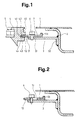
- FIG. 1 shows a vehicle wall 1, on the inside of which an inverted S-shaped profile 2 with spot welding is fastened.
- a bracket 3 On the vertical middle part of the profile 2, a bracket 3 is welded to its short-leg foot 3.2. At the upper or side end on the left there is a threaded hole 3.1.
- a displaceable wedge piece 7 is screwed to the bracket 3 with a screw 6 and has a short vertical leg 7.3 on the right, a slot 7.1 approximately in the middle and a wedge-shaped tapered end 7.2 on the left.
- the wedge-shaped tapered end 7.2 sits firmly in a keyway 4.1 with a basically free space 4.4 and outwardly sloping flanks 4.3 on the inside and 4.2 on the outside.
- the keyway 4.1 is located in a window frame profile 4, which surrounds a window pane 5 and has a profile groove 4.5 at the top right.
- FIG. 2 shows the wedge piece 7 in the reset position.
- the left end of the slot 7.1 abuts the screw 6.
- Figure 3 shows a cross section through the lower horizontal frame part of a fully installed window.
- a fixed wedge piece 8 with a bore 8.1 is screwed onto the mounting bracket 3 in a clear position.
- An upward wedge-shaped end 8.2 sits firmly in the keyway 4.1 of the window frame profile 4.
- the opening between the window frame profile 4 and the upper edge of the vehicle wall 1 is closed with a cover profile 9.
- the cover profile 9 is guided in the window frame profile 4 in a profile groove 4.5 and overlaps the outside of the window frame profile 4.
- the cover profile 9 encloses the upper end of the vehicle wall 1 on the inside and outside.
- a spreading insert 10 ensures a permanent, firm hold of the cover profile 9.
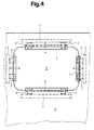
- FIG. 4 shows the overall view of a window opening 11 in a vehicle wall 1.
- the displaceability of the wedge pieces 7 on both sides and above is indicated by a double arrow.
- the fixed wedge piece 8 is located on the lower horizontal part of the window opening 11.
- the device described above works as follows: Before installing a window pane 5 with a window frame profile 4 in a window opening 11, the displaceable wedge pieces 7 are pushed into their outermost position and blocked there with the screws 6, so that a maximally large installation opening is created. Then one with the Window frame profile 4 provided window pane 5 placed on the fixed wedge piece 8 and brought into a vertical position, so that the wedge-shaped tapered end 8.2 of the wedge piece 8 sits firmly in the keyway 4.1. The upper horizontal wedge piece 7 is then loosened, pressed into the keyway 4.1 and screwed tight again. The same process takes place on the left and right vertical side of the window opening 11. The installation work is completed by inserting the cover profile 9 and fixing it with the spreading insert 10. The removal takes place in reverse order. A vehicle window installed in this way sits firmly and without play in its holder and can be replaced within a few minutes in the event of damage.
- the wedge pieces 7 can have a spring preload and jump into the wedge groove 4.1 after installation after releasing a lock.
- the device described can also be used for road vehicles.
Landscapes
- Engineering & Computer Science (AREA)
- Mechanical Engineering (AREA)
- Civil Engineering (AREA)
- Structural Engineering (AREA)
- Window Of Vehicle (AREA)
Abstract
Description
- Die vorliegende Erfindung betrifft eine Vorrichtung für den Einbau/Ausbau und die Befestigung von aus Rahmen und Scheiben bestehenden Fenstern mittels mechanischen Befestigungselementen in Fensteröffnungen bei Schienenfahrzeugen.
- Es sind für die Halterung von Fenstern verschiedene Verfahren und Vorrichtungen bekannt.
- Die Offenlegungsschrift DE 34 37 200 A1 beschreibt einen Fensterrahmen zum Einbau in einen Fahrzeugwandausschnitt. Das Fensterrahmenprofil weist stirnseitig eine schwalbenschwanzförmige Nut auf, in welche Gleitstücke mit Klemmschrauben eingesetzt werden. Klemmschraube und Profilschenkel umfassen den äusseren Rand der Fahrzeugwand und werden an diesem durch Anziehen der Schrauben angeklemmt. Beim Einbau wird das Fenster von aussen in die Öffnung eingeschoben, dann werden von innen die Gleitstücke eingesetzt und die Klemmschrauben angezogen. Zum Abschluss muss noch die Innenverkleidung angebracht werden.
- Nachteilig wirkt sich bei dieser Erfindung aus, dass gleichzeitig von innen und aussen operiert werden muss, und dass die Innenverkleidung dabei montiert bzw. demontiert werden muss. Ferner können die Gleitstücke bei viel Spiel in der Nut kippen, verkanten und die Klemmschraube unzugänglich machen. Bei weniger Spiel zwischen Nut und Gleitstücken müssen spezielle Ausfräsungen vorgesehen werden, um die Gleitstücke einführen zu können.
- Der vorliegenden Erfindung liegt die Aufgabe zugrunde, eine Vorrichtung für den Fenstereinbau zu schaffen, welche keinen der genannten Nachteile aufweist und mittels welcher der Ein/Ausbau und die Befestigung der Fenster mit weniger Aufwand verbunden ist.
- Diese Aufgabe wird durch die in den Ansprüchen gekennzeichnete Erfindung gelöst.
- Die durch die Erfindung erreichten Vorteile sind im wesentlichen darin zu sehen, dass der Ein/Ausbau und die Befestigung sowie das Lösen der Fenster von der Aussenseite des Fahrzeuges erfolgen können und dadurch keine Montage und Demontage der Innenverkleidung nötig ist. Ferner ist, gegeben durch die Art der Befestigung, der zeitliche Aufwand auf wenige Minuten beschränkt.
- In den Zeichnungen ist ein Ausführungsbeispiel dargestellt und es zeigen:
- Fig. 1 einen Querschnitt mit arretiertem Fensterrahmen,
- Fig. 2 einen Querschnitt mit zurückgezogenem Keilstück,
- Fig. 3 einen Querschnitt mit festem Keilstück und eingesetztem Deckprofil und
- Fig. 4 eine Aussenansicht einer Fensteröffnung.
- Die Figur 1 zeigt eine Fahrzeugwand 1, an welcher innenseitig ein umgekehrt S-förmiges Profil 2 mit Punktschweissung befestigt ist. Auf dem vertikalen Mittelteil des Profiles 2 ist ein Haltewinkel 3 an seinem kurzschenkligen Fuss 3.2 angeschweisst. Am oberen bzw. seitlichen Ende links ist eine Gewindebohrung 3.1 vorhanden. Mit einer Schraube 6 ist am Haltewinkel 3 ein verschiebbares Keilstück 7 angeschraubt, welches rechts einen kurzen vertikalen Schenkel 7.3, ca. in der Mitte einen Schlitz 7.1 und links ein keilförmig verjüngtes Ende 7.2 aufweist. Das keilförmig verjüngte Ende 7.2 sitzt fest in einer Keilnut 4.1 mit einem im Grunde freien Raum 4.4 und nach aussen schrägen Flanken 4.3 innenseitig und 4.2 aussenseitig. Die Keilnut 4.1 befindet sich in einem Fensterrahmenprofil 4, welches eine Fensterscheibe 5 einfasst und rechts oben eine Profilnut 4.5 aufweist.
- Die Figur 2 zeigt das Keilstück 7 in zurückgestellter Position. Das linke Ende des Schlitzes 7.1 liegt an der Schraube 6 an.
- Die Figur 3 zeigt einen Querschnitt durch den unteren horizontalen Rahmenteil eines fertig eingebauten Fensters. Am Haltewinkel 3 ist hier ein festes Keilstück 8 mit einer Bohrung 8.1 in einer eindeutigen Position angeschraubt. Ein nach oben keilförmig verjüngtes Ende 8.2 sitzt fest in der Keilnut 4.1 des Fensterrahmenprofils 4. Die Öffnung zwischen Fensterrahmenprofil 4 und oberer Kante der Fahrzeugwand 1 ist mit einem Deckprofil 9 geschlossen. Das Deckprofil 9 ist beim Fensterrahmenprofil 4 in einer Profilnut 4.5 geführt und überlappt die Aussenseite des Fensterrahmenprofils 4. Ferner umschliesst das Deckprofil 9 das obere Ende der Fahrzeugwand 1 innen- und aussenseitig. Eine Spreizeinlage 10 sorgt für dauernd festen Halt des Deckprofils 9.
- Die Figur 4 zeigt die Gesamtansicht einer Fensteröffnung 11 in einer Fahrzeugwand 1. Die Verschiebbarkeit der Keilstücke 7 auf beiden Seiten und oben ist je mit einem Doppelpfeil angegeben. Das feste Keilstück 8 befindet sich am unteren horizontalen Teil der Fensteröffnung 11.
- Die vorstehend beschriebene Vorrichtung arbeitet wie folgt: Vor dem Einbau einer Fensterscheibe 5 mit Fensterrahmenprofil 4 in eine Fensteröffnung 11 werden die verschiebbaren Keilstücke 7 in ihre äusserste Position geschoben und dort mit den Schrauben 6 blockiert, so dass eine maximal grosse Einbauöffnung entsteht. Dann wird eine mit dem Fensterrahmenprofil 4 versehene Fensterscheibe 5 auf das feste Keilstück 8 abgestellt und in senkrechte Lage gebracht, so dass das keilförmig verjüngte Ende 8.2 des Keilstückes 8 fest in der Keilnut 4.1 sitzt. Darauf wird das obere horizontale Keilstück 7 gelöst, in die Keilnut 4.1 gedrückt und wieder festgeschraubt. Der gleiche Vorgang erfolgt auf der linken und rechten vertikalen Seite der Fensteröffnung 11. Die Einbauarbeit wird mit dem Einlegen des Deckprofils 9 und dessen Fixierung mit der Spreizeinlage 10 abgeschlossen. Der Ausbau erfolgt in umgekehrter Reihenfolge. Ein so eingebautes Fahrzeugfenster sitzt fest und spielfrei in seiner Halterung und kann im Schadenfalle innert einigen Minuten ausgewechselt werden.
- In einer weitergebildeten Form können die Keilstücke 7 eine Federvorspannung aufweisen und beim Einbau nach Lösen einer Arretierung von selbst in die Keilnut 4.1 springen.
- Die beschriebene Vorrichtung lässt sich auch für Strassenfahrzeuge verwenden.
Claims (6)
dadurch gekennzeichnet,
dass zwischen einem Fensterrahmen (4) und einer Fahrzeugwand (1) mindestens eine kraft- und formschlüssige Nut/Keilverbindung vorhanden ist.
dadurch gekennzeichnet,
dass mindestens ein in paralleler Richtung zur Fensterebene verschiebbares Keilstück (7) vorhanden ist.
dadurch gekennzeichnet,
dass ein nicht verschiebbares Keilstück (8) vorhanden ist.
dadurch gekennzeichnet,
dass der Fensterrahmen (4) stirnseitig eine auf die Keilstücke (7; 8) passende Keilnut (4.1) aufweist.
dadurch gekennzeichnet,
dass Nutflanken (4.2; 4.3) der Keilnut (4.1) eine die spielfreie Befestigung ermöglichende Schräge nach aussen und die Keilstücke (7; 8) stirnseitig ein keilförmig verjüngtes in die Keilnut (4.1) passendes Ende (7.2; 8.2) aufweisen.
dadurch gekennzeichnet,
dass ein den Zwischenraum zwischen Fahrzeugwand (1) und Festerrahmen (4) deckendes vom Fenstergewicht unbelastetes Deckprofil (9) vorhanden ist.
Priority Applications (1)
| Application Number | Priority Date | Filing Date | Title |
|---|---|---|---|
| AT90108344T ATE98580T1 (de) | 1989-05-16 | 1990-05-03 | Vorrichtung fuer die halterung von fensterscheiben, insbesondere bei schienenfahrzeugen. |
Applications Claiming Priority (2)
| Application Number | Priority Date | Filing Date | Title |
|---|---|---|---|
| CH1813/89 | 1989-05-16 | ||
| CH181389 | 1989-05-16 |
Publications (3)
| Publication Number | Publication Date |
|---|---|
| EP0398077A2 true EP0398077A2 (de) | 1990-11-22 |
| EP0398077A3 EP0398077A3 (de) | 1991-03-27 |
| EP0398077B1 EP0398077B1 (de) | 1993-12-15 |
Family
ID=4219198
Family Applications (1)
| Application Number | Title | Priority Date | Filing Date |
|---|---|---|---|
| EP90108344A Expired - Lifetime EP0398077B1 (de) | 1989-05-16 | 1990-05-03 | Vorrichtung für die Halterung von Fensterscheiben, insbesondere bei Schienenfahrzeugen |
Country Status (4)
| Country | Link |
|---|---|
| EP (1) | EP0398077B1 (de) |
| AT (1) | ATE98580T1 (de) |
| DE (1) | DE59003839D1 (de) |
| ES (1) | ES2049365T3 (de) |
Cited By (3)
| Publication number | Priority date | Publication date | Assignee | Title |
|---|---|---|---|---|
| FR2771055A1 (fr) * | 1997-11-18 | 1999-05-21 | Saint Gobain Vitrage | Vitrage demontable rapidement |
| FR2859690A1 (fr) * | 2003-09-11 | 2005-03-18 | Alstom | Procede de montage d'un vitrage affleurant |
| WO2021191517A1 (fr) * | 2020-03-25 | 2021-09-30 | Saint-Gobain Glass France | Systeme de fixation d'un vitrage lateral de moyen de transport avec un verrou |
Family Cites Families (4)
| Publication number | Priority date | Publication date | Assignee | Title |
|---|---|---|---|---|
| CH400520A (de) * | 1962-01-30 | 1965-10-15 | Rune Flodell Stig Axel | Vorrichtung zum Einstellen und Festhalten von Fensterblend- oder Türrahmen |
| DE2328367C2 (de) * | 1973-06-04 | 1975-07-17 | E. Albers & V. Drathen, 2223 Meldorf | Halterung für feststehende Rahmen von Fenstern, Türen oder dergleichen |
| DE8301436U1 (de) * | 1983-01-20 | 1988-09-15 | Messerschmitt-Boelkow-Blohm Gmbh, 8012 Ottobrunn, De | |
| DE3344180A1 (de) * | 1983-12-07 | 1985-06-13 | Messerschmitt-Bölkow-Blohm GmbH, 8012 Ottobrunn | Fahrzeugfenster |
-
1990
- 1990-05-03 DE DE90108344T patent/DE59003839D1/de not_active Expired - Lifetime
- 1990-05-03 EP EP90108344A patent/EP0398077B1/de not_active Expired - Lifetime
- 1990-05-03 AT AT90108344T patent/ATE98580T1/de not_active IP Right Cessation
- 1990-05-03 ES ES90108344T patent/ES2049365T3/es not_active Expired - Lifetime
Cited By (11)
| Publication number | Priority date | Publication date | Assignee | Title |
|---|---|---|---|---|
| FR2771055A1 (fr) * | 1997-11-18 | 1999-05-21 | Saint Gobain Vitrage | Vitrage demontable rapidement |
| WO1999025575A1 (fr) * | 1997-11-18 | 1999-05-27 | Saint-Gobain Vitrage | Vitrage demontable rapidement |
| JP2001508731A (ja) * | 1997-11-18 | 2001-07-03 | サン−ゴバン・ヴイトラージユ | 迅速に取外せる窓ガラス |
| US6364404B1 (en) | 1997-11-18 | 2002-04-02 | Saint-Gobain Vitrage | Quickly detachable glazing sheet |
| US6460917B2 (en) | 1997-11-18 | 2002-10-08 | Saint-Gobain Vitrage | Quickly detachable glazing sheet |
| KR100546811B1 (ko) * | 1997-11-18 | 2006-01-26 | 쌩-고벵 글래스 프랑스 | 개구부에 창유리를 끼워맞춤하기 위한 시스템 |
| FR2859690A1 (fr) * | 2003-09-11 | 2005-03-18 | Alstom | Procede de montage d'un vitrage affleurant |
| EP1564102A3 (de) * | 2003-09-11 | 2005-08-24 | Alstom | Verfahren zur Montage eines bündig montierten, nicht bewegbaren Fensters |
| US7188399B2 (en) | 2003-09-11 | 2007-03-13 | Alstom | Method of fitting flush glazing |
| WO2021191517A1 (fr) * | 2020-03-25 | 2021-09-30 | Saint-Gobain Glass France | Systeme de fixation d'un vitrage lateral de moyen de transport avec un verrou |
| FR3108576A1 (fr) * | 2020-03-25 | 2021-10-01 | Saint-Gobain Glass France | Systeme de fixation d’un vitrage lateral de moyen de transport avec un verrou |
Also Published As
| Publication number | Publication date |
|---|---|
| ES2049365T3 (es) | 1994-04-16 |
| DE59003839D1 (de) | 1994-01-27 |
| EP0398077A3 (de) | 1991-03-27 |
| EP0398077B1 (de) | 1993-12-15 |
| ATE98580T1 (de) | 1994-01-15 |
Similar Documents
| Publication | Publication Date | Title |
|---|---|---|
| DE3801816C2 (de) | Befestigungsvorrichtung für einstellbare Frontblenden von Schubladen | |
| DE102014104920B4 (de) | Karosseriestruktur mit Dach-Reling | |
| DE19708387A1 (de) | Baukasten zur Erstellung eines automatischen Schiebetürantriebs | |
| DE1941316A1 (de) | Plattenfoermige Ballastgewichte,insbesondere fuer landwirtschaftlich nutzbare Motorfahrzeuge | |
| DE2458566C2 (de) | ||
| DE4005953C2 (de) | ||
| DE29600180U1 (de) | Justiereinrichtung für Unterflurauszugführungen | |
| DE202010014922U1 (de) | Befestigung einer Antriebsschiene oder eines Antriebsschienenabschnittes mit einem Antriebskopf eines automatisierten Tores oder dergleichen | |
| DE3140855C2 (de) | Vorrichtung zum Betätigen einer Ausstellschere für die Flügel von Fenstern, Türen oder dergleichen | |
| EP0398077A2 (de) | Vorrichtung für die Halterung von Fensterscheiben, insbesondere bei Schienenfahrzeugen | |
| DE29907856U1 (de) | Führungsvorrichtung zur Aufnahme von Gleit- und Schiebeelementen an Möbeln | |
| EP0872408A2 (de) | Cockpitbereich für ein Kraftfahrzeug | |
| DE4445303C1 (de) | Sonnenschutzanlage | |
| DE2463127C2 (de) | ||
| DE3126634A1 (de) | Tuerscharnier fuer kraftfahrzeugtueren | |
| DE8115218U1 (de) | "schiebetuer fuer den einbau in eine maueraussparung o.dgl." | |
| DE19503263B4 (de) | Markise | |
| DE4403159C2 (de) | Entwässerungsrinne | |
| AT514207B1 (de) | Vorrichtung zum Befestigen eines Rollos | |
| DE29501259U1 (de) | Netzhakenanordnung zum Einhängen des Ballfangnetzes an Toren | |
| DE29618677U1 (de) | Schiebebeschlag für Türen, Fenster o.dgl. | |
| DE3217413A1 (de) | Vorrichtung zur befestigung von schwellenschienen an holzzargen | |
| DE102016013751C5 (de) | Nutzfahrzeugaufbau | |
| DE20201673U1 (de) | Befestigungsvorrichtung | |
| DE3629686C2 (de) |
Legal Events
| Date | Code | Title | Description |
|---|---|---|---|
| PUAI | Public reference made under article 153(3) epc to a published international application that has entered the european phase |
Free format text: ORIGINAL CODE: 0009012 |
|
| AK | Designated contracting states |
Kind code of ref document: A2 Designated state(s): AT CH DE ES FR GB IT LI |
|
| PUAL | Search report despatched |
Free format text: ORIGINAL CODE: 0009013 |
|
| AK | Designated contracting states |
Kind code of ref document: A3 Designated state(s): AT CH DE ES FR GB IT LI |
|
| 17P | Request for examination filed |
Effective date: 19910829 |
|
| 17Q | First examination report despatched |
Effective date: 19920917 |
|
| GRAA | (expected) grant |
Free format text: ORIGINAL CODE: 0009210 |
|
| AK | Designated contracting states |
Kind code of ref document: B1 Designated state(s): AT CH DE ES FR GB IT LI |
|
| REF | Corresponds to: |
Ref document number: 98580 Country of ref document: AT Date of ref document: 19940115 Kind code of ref document: T |
|
| REF | Corresponds to: |
Ref document number: 59003839 Country of ref document: DE Date of ref document: 19940127 |
|
| GBT | Gb: translation of ep patent filed (gb section 77(6)(a)/1977) |
Effective date: 19940111 |
|
| ET | Fr: translation filed | ||
| ITF | It: translation for a ep patent filed | ||
| REG | Reference to a national code |
Ref country code: ES Ref legal event code: FG2A Ref document number: 2049365 Country of ref document: ES Kind code of ref document: T3 |
|
| PLBE | No opposition filed within time limit |
Free format text: ORIGINAL CODE: 0009261 |
|
| STAA | Information on the status of an ep patent application or granted ep patent |
Free format text: STATUS: NO OPPOSITION FILED WITHIN TIME LIMIT |
|
| 26N | No opposition filed | ||
| REG | Reference to a national code |
Ref country code: CH Ref legal event code: NV Representative=s name: ASEA BROWN BOVERI AG Ref country code: CH Ref legal event code: PUE Owner name: INVENTIO AG TRANSFER- ABB DAIMLER-BENZ TRANSPORTAT |
|
| REG | Reference to a national code |
Ref country code: ES Ref legal event code: PC2A |
|
| REG | Reference to a national code |
Ref country code: GB Ref legal event code: 732E |
|
| REG | Reference to a national code |
Ref country code: FR Ref legal event code: TP |
|
| REG | Reference to a national code |
Ref country code: FR Ref legal event code: TP |
|
| REG | Reference to a national code |
Ref country code: CH Ref legal event code: NV Representative=s name: DAIMLERCHRYSLER AG INTELLECTUAL PROPERTY MANAGEMEN |
|
| REG | Reference to a national code |
Ref country code: CH Ref legal event code: PUE Owner name: ABB DAIMLER-BENZ TRANSPORTATION (SCHWEIZ) AG -DANN |
|
| REG | Reference to a national code |
Ref country code: GB Ref legal event code: 732E |
|
| REG | Reference to a national code |
Ref country code: FR Ref legal event code: TP |
|
| REG | Reference to a national code |
Ref country code: CH Ref legal event code: PUE Owner name: DAIMLERCHRYSLER AG TRANSFER- DAIMLERCHRYSLER RAIL Ref country code: CH Ref legal event code: NV Representative=s name: ROTTMANN, ZIMMERMANN + PARTNER AG |
|
| REG | Reference to a national code |
Ref country code: GB Ref legal event code: IF02 |
|
| PGFP | Annual fee paid to national office [announced via postgrant information from national office to epo] |
Ref country code: GB Payment date: 20031002 Year of fee payment: 14 |
|
| PGFP | Annual fee paid to national office [announced via postgrant information from national office to epo] |
Ref country code: FR Payment date: 20031016 Year of fee payment: 14 |
|
| PGFP | Annual fee paid to national office [announced via postgrant information from national office to epo] |
Ref country code: ES Payment date: 20031020 Year of fee payment: 14 |
|
| PG25 | Lapsed in a contracting state [announced via postgrant information from national office to epo] |
Ref country code: GB Free format text: LAPSE BECAUSE OF NON-PAYMENT OF DUE FEES Effective date: 20040503 |
|
| PG25 | Lapsed in a contracting state [announced via postgrant information from national office to epo] |
Ref country code: ES Free format text: LAPSE BECAUSE OF NON-PAYMENT OF DUE FEES Effective date: 20040504 |
|
| GBPC | Gb: european patent ceased through non-payment of renewal fee |
Effective date: 20040503 |
|
| PG25 | Lapsed in a contracting state [announced via postgrant information from national office to epo] |
Ref country code: FR Free format text: LAPSE BECAUSE OF NON-PAYMENT OF DUE FEES Effective date: 20050131 |
|
| REG | Reference to a national code |
Ref country code: FR Ref legal event code: ST |
|
| PG25 | Lapsed in a contracting state [announced via postgrant information from national office to epo] |
Ref country code: IT Free format text: LAPSE BECAUSE OF NON-PAYMENT OF DUE FEES Effective date: 20050503 |
|
| REG | Reference to a national code |
Ref country code: ES Ref legal event code: FD2A Effective date: 20040504 |
|
| PGFP | Annual fee paid to national office [announced via postgrant information from national office to epo] |
Ref country code: AT Payment date: 20090515 Year of fee payment: 20 Ref country code: DE Payment date: 20090525 Year of fee payment: 20 |
|
| PGFP | Annual fee paid to national office [announced via postgrant information from national office to epo] |
Ref country code: CH Payment date: 20090518 Year of fee payment: 20 |
|
| REG | Reference to a national code |
Ref country code: CH Ref legal event code: PL |
|
| PG25 | Lapsed in a contracting state [announced via postgrant information from national office to epo] |
Ref country code: DE Free format text: LAPSE BECAUSE OF EXPIRATION OF PROTECTION Effective date: 20100503 |