EP0398152A2 - Herse vibratoire motorisée - Google Patents
Herse vibratoire motorisée Download PDFInfo
- Publication number
- EP0398152A2 EP0398152A2 EP90108774A EP90108774A EP0398152A2 EP 0398152 A2 EP0398152 A2 EP 0398152A2 EP 90108774 A EP90108774 A EP 90108774A EP 90108774 A EP90108774 A EP 90108774A EP 0398152 A2 EP0398152 A2 EP 0398152A2
- Authority
- EP
- European Patent Office
- Prior art keywords
- fork
- harrow
- rocker
- gear housing
- bearing
- Prior art date
- Legal status (The legal status is an assumption and is not a legal conclusion. Google has not performed a legal analysis and makes no representation as to the accuracy of the status listed.)
- Withdrawn
Links
Images
Classifications
-
- A—HUMAN NECESSITIES
- A01—AGRICULTURE; FORESTRY; ANIMAL HUSBANDRY; HUNTING; TRAPPING; FISHING
- A01B—SOIL WORKING IN AGRICULTURE OR FORESTRY; PARTS, DETAILS, OR ACCESSORIES OF AGRICULTURAL MACHINES OR IMPLEMENTS, IN GENERAL
- A01B19/00—Harrows with non-rotating tools
- A01B19/02—Harrows with non-rotating tools with tools rigidly or elastically attached to a tool-frame
- A01B19/06—Harrows with non-rotating tools with tools rigidly or elastically attached to a tool-frame with tools or tool-frames moved to-and-fro mechanically
Definitions
- the invention relates to a PTO-driven harrow according to the preamble of claim 1.
- Such a harrow is known for example from the German utility model 82 01 995.
- the fork swing arm is only supported on the underside in the gear housing and via the swashplate drive on the drive shaft. This results in a simple and compact design of the wobble body drive and the gear housing.
- the invention has for its object to achieve a much smoother running of the power harrow, in particular the vibration drive in a structurally simple manner.
- This object is achieved in that another bearing for mounting the fork rocker is arranged on / in the gear housing in the same alignment with the fork rocker which rotates back and forth about a vertical axis.
- This measure according to the invention results in extremely smooth running of the vibrating harrow and the vibration drive in the simplest way. A considerably higher number of vibrations of the harrow beams is possible without causing early gear damage, etc.
- the further bearing is arranged on the upper side of the fork rocker and thus supports the fork rocker in the cover wall of the transmission housing, the bearing being arranged on a bridge connecting the fork.
- the bridge is screwed onto the fork ends of the fork or that the bridge is integrally connected to the fork ends of the fork. It is also possible to arrange the further bearing below the other bearing.
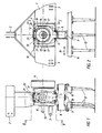
- the power harrow has a frame 1 on which the three-point coupling elements 2 and 3 are arranged, via which the power harrow is to be coupled to the three-point linkage of an agricultural tractor.
- the frame of the harrow extends across the direction of travel.
- the gear housing 4 is arranged in the middle of the frame 1.
- the fork rocker 5 is mounted on the bearings 6 and 7.
- the rocker 8 is arranged in the gearbox 4.
- 1 more rockers 8 are mounted in the outer region of the frame.
- the harrow beams 10 and 11 are screwed to these rockers 8 via the rocking shaft 9.
- On the harrow beams 10 and 11 are the tillage tines 12, which are screwed onto the harrow beams 10 and 11.
- the harrow beams 10 and 11 extend transversely to the direction of travel.
- the drive shaft 13 is mounted in the gear housing 4.
- the wobble body 14 is wedged and fastened on the drive shaft 13.
- the swash body 15 is supported on the swash body 14.
- the swash body 15 has the two journals 16.
- the forks 17 of the fork rocker 5 are placed on the bearing journal 16.
- the wobble body 14 is driven in rotation by the drive shaft 13, which is connected to the PTO shaft of the tractor pulling the power harrow via an articulated shaft (not shown).
- the wobble body 14 is set in reciprocating movements, so that the harrow beam, as indicated by the double arrow 18, is set in reciprocating vibrations.
- the fork rocker 5 is supported by the bearing 6 on its underside in the transmission housing 4.
- the fork ends 19 are connected to one another via the bridge 20, in that the bridge 20 is screwed to the fork ends 19 of the fork 17 of the fork rocker 5 via the screws 21.
- the further bearing 7 is arranged, with which the fork rocker 5 is additionally mounted in the cover wall 22 of the housing 4.
- the upper bearing 7 is arranged in the same alignment with the fork rocker 5 which rotates back and forth about the vertical axis in the gear housing 4.
Landscapes
- Life Sciences & Earth Sciences (AREA)
- Engineering & Computer Science (AREA)
- Mechanical Engineering (AREA)
- Soil Sciences (AREA)
- Environmental Sciences (AREA)
- Soil Working Implements (AREA)
Applications Claiming Priority (2)
| Application Number | Priority Date | Filing Date | Title |
|---|---|---|---|
| DE3916299 | 1989-05-19 | ||
| DE19893916299 DE3916299A1 (de) | 1989-05-19 | 1989-05-19 | Zapfwellengetriebene ruettelegge |
Publications (2)
| Publication Number | Publication Date |
|---|---|
| EP0398152A2 true EP0398152A2 (fr) | 1990-11-22 |
| EP0398152A3 EP0398152A3 (fr) | 1991-07-24 |
Family
ID=6380952
Family Applications (1)
| Application Number | Title | Priority Date | Filing Date |
|---|---|---|---|
| EP19900108774 Withdrawn EP0398152A3 (fr) | 1989-05-19 | 1990-05-10 | Herse vibratoire motorisée |
Country Status (5)
| Country | Link |
|---|---|
| EP (1) | EP0398152A3 (fr) |
| CS (1) | CS239990A2 (fr) |
| DD (1) | DD294397A5 (fr) |
| DE (1) | DE3916299A1 (fr) |
| HU (1) | HU204942B (fr) |
Families Citing this family (2)
| Publication number | Priority date | Publication date | Assignee | Title |
|---|---|---|---|---|
| DE20217613U1 (de) * | 2002-11-13 | 2004-04-01 | Müllers & Backhaus GmbH & Co. KG | Translatorisch bewegtes Bodenbearbeitungsgerät |
| DE102008001176B4 (de) | 2008-04-14 | 2010-01-07 | Bernd Von Hermanni | Formkörper und Verfahren zur Herstellung eines Formkörpers |
Family Cites Families (4)
| Publication number | Priority date | Publication date | Assignee | Title |
|---|---|---|---|---|
| DE233302C (fr) * | ||||
| US2505978A (en) * | 1946-02-12 | 1950-05-02 | Associated Engineers Inc | Mechanical drive mechanism |
| DE1557679A1 (de) * | 1967-07-11 | 1970-04-02 | Heinrich Wilhelm Dreyer Landma | Ruettelegge |
| FR2513480A1 (fr) * | 1981-09-29 | 1983-04-01 | Howard Machinery Ltd | Herse vibrante |
-
1989
- 1989-05-19 DE DE19893916299 patent/DE3916299A1/de not_active Withdrawn
-
1990
- 1990-05-10 EP EP19900108774 patent/EP0398152A3/fr not_active Withdrawn
- 1990-05-17 HU HU306590A patent/HU204942B/hu not_active IP Right Cessation
- 1990-05-17 CS CS902399A patent/CS239990A2/cs unknown
- 1990-05-18 DD DD34082990A patent/DD294397A5/de not_active IP Right Cessation
Also Published As
| Publication number | Publication date |
|---|---|
| HU204942B (en) | 1992-03-30 |
| HUT55182A (en) | 1991-05-28 |
| DD294397A5 (de) | 1991-10-02 |
| HU903065D0 (en) | 1990-09-28 |
| EP0398152A3 (fr) | 1991-07-24 |
| DE3916299A1 (de) | 1990-11-22 |
| CS239990A2 (en) | 1991-09-15 |
Similar Documents
| Publication | Publication Date | Title |
|---|---|---|
| EP0041136A1 (fr) | Entraînement orientable pour éléments pivotants de machines, en particulier pour manipulateurs | |
| DE2251808B2 (de) | Zahnaerztlicher patientenstuhl mit parallelogrammtragarm | |
| DE69911864T2 (de) | Handwerkzeugmaschine mit elektrischem Antrieb, insbesondere Stichsäge | |
| DE2524464A1 (de) | Maehwerkantrieb | |
| DE68904246T2 (de) | Landmaschine mit mindestens einem waehrend der arbeit angetriebenen rechrad. | |
| EP0398152A2 (fr) | Herse vibratoire motorisée | |
| EP0355365A1 (fr) | Tondeuse à gazon | |
| DE9010176U1 (de) | Heuwerbungsmaschine | |
| EP1574750B1 (fr) | Transmission | |
| EP1295520B1 (fr) | Herse rotative à entrainement du rotor amélioré | |
| DE1757445B2 (de) | Bodenbearbeitungsmaschine | |
| EP1012404A1 (fr) | Instrument de travail a equilibrage des masses sur la commande a manivelle | |
| DE8915803U1 (de) | Zapfwellengetriebene Rüttelegge | |
| DE2044029C3 (de) | Landwirtschaftliches Gerät zur Bodenbearbeitung | |
| DE859075C (de) | Zapfwellenantrieb fuer die Erzeugung schwingender und drehender Bewegungen | |
| DE1258645B (de) | Ruettelegge mit einem durch Zapfwelle angetriebenen Rotationskoerper | |
| DE69916533T2 (de) | Mäher/Konditionierer | |
| DE69010070T2 (de) | Mähmaschine. | |
| DE69012603T2 (de) | Mähvorrichtung. | |
| DE4243755A1 (de) | Außenrüttler | |
| DE1907349C (de) | Vorrichtung zum Verstellen einer Exzenteranordnung | |
| DE1053842B (de) | Maehwerk mit einem hydraulischen Motor | |
| DE9312143U1 (de) | Rundballenpresse für landwirtschaftliche Erntegüter | |
| AT528251A1 (de) | Kraftheber mit elektrischer Antriebseinheit | |
| DE19715837A1 (de) | Antriebsachse |
Legal Events
| Date | Code | Title | Description |
|---|---|---|---|
| PUAI | Public reference made under article 153(3) epc to a published international application that has entered the european phase |
Free format text: ORIGINAL CODE: 0009012 |
|
| AK | Designated contracting states |
Kind code of ref document: A2 Designated state(s): BE DE FR GB IT NL |
|
| PUAL | Search report despatched |
Free format text: ORIGINAL CODE: 0009013 |
|
| AK | Designated contracting states |
Kind code of ref document: A3 Designated state(s): BE DE FR GB IT NL |
|
| 17P | Request for examination filed |
Effective date: 19910823 |
|
| 17Q | First examination report despatched |
Effective date: 19920722 |
|
| STAA | Information on the status of an ep patent application or granted ep patent |
Free format text: STATUS: THE APPLICATION IS DEEMED TO BE WITHDRAWN |
|
| 18D | Application deemed to be withdrawn |
Effective date: 19921202 |