EP0398253B1 - Schneidwerkzeughalter mit Abstreifvorrichtung - Google Patents
Schneidwerkzeughalter mit Abstreifvorrichtung Download PDFInfo
- Publication number
- EP0398253B1 EP0398253B1 EP19900109134 EP90109134A EP0398253B1 EP 0398253 B1 EP0398253 B1 EP 0398253B1 EP 19900109134 EP19900109134 EP 19900109134 EP 90109134 A EP90109134 A EP 90109134A EP 0398253 B1 EP0398253 B1 EP 0398253B1
- Authority
- EP
- European Patent Office
- Prior art keywords
- punch
- holder
- sleeve
- holder member
- inner sleeve
- Prior art date
- Legal status (The legal status is an assumption and is not a legal conclusion. Google has not performed a legal analysis and makes no representation as to the accuracy of the status listed.)
- Expired - Lifetime
Links
- JOYRKODLDBILNP-UHFFFAOYSA-N Ethyl urethane Chemical compound CCOC(N)=O JOYRKODLDBILNP-UHFFFAOYSA-N 0.000 claims description 3
- 239000004033 plastic Substances 0.000 claims description 3
- 229920003023 plastic Polymers 0.000 claims description 3
- 238000004080 punching Methods 0.000 claims description 3
- 239000013013 elastic material Substances 0.000 claims 1
- 230000006835 compression Effects 0.000 description 5
- 238000007906 compression Methods 0.000 description 5
- 239000000463 material Substances 0.000 description 5
- 229910000831 Steel Inorganic materials 0.000 description 2
- 239000002131 composite material Substances 0.000 description 2
- 229910052751 metal Inorganic materials 0.000 description 2
- 239000002184 metal Substances 0.000 description 2
- 230000035515 penetration Effects 0.000 description 2
- 239000010959 steel Substances 0.000 description 2
- 229910052782 aluminium Inorganic materials 0.000 description 1
- XAGFODPZIPBFFR-UHFFFAOYSA-N aluminium Chemical compound [Al] XAGFODPZIPBFFR-UHFFFAOYSA-N 0.000 description 1
- 238000011161 development Methods 0.000 description 1
- 230000018109 developmental process Effects 0.000 description 1
- 238000004519 manufacturing process Methods 0.000 description 1
- 230000013011 mating Effects 0.000 description 1
- 239000002991 molded plastic Substances 0.000 description 1
- 230000002093 peripheral effect Effects 0.000 description 1
- 230000000717 retained effect Effects 0.000 description 1
- 229910001220 stainless steel Inorganic materials 0.000 description 1
- 239000010935 stainless steel Substances 0.000 description 1
Images

Classifications
-
- B—PERFORMING OPERATIONS; TRANSPORTING
- B21—MECHANICAL METAL-WORKING WITHOUT ESSENTIALLY REMOVING MATERIAL; PUNCHING METAL
- B21D—WORKING OR PROCESSING OF SHEET METAL OR METAL TUBES, RODS OR PROFILES WITHOUT ESSENTIALLY REMOVING MATERIAL; PUNCHING METAL
- B21D45/00—Ejecting or stripping-off devices arranged in machines or tools dealt with in this subclass
- B21D45/003—Ejecting or stripping-off devices arranged in machines or tools dealt with in this subclass in punching machines or punching tools
- B21D45/006—Stripping-off devices
-
- Y—GENERAL TAGGING OF NEW TECHNOLOGICAL DEVELOPMENTS; GENERAL TAGGING OF CROSS-SECTIONAL TECHNOLOGIES SPANNING OVER SEVERAL SECTIONS OF THE IPC; TECHNICAL SUBJECTS COVERED BY FORMER USPC CROSS-REFERENCE ART COLLECTIONS [XRACs] AND DIGESTS
- Y10—TECHNICAL SUBJECTS COVERED BY FORMER USPC
- Y10T—TECHNICAL SUBJECTS COVERED BY FORMER US CLASSIFICATION
- Y10T83/00—Cutting
- Y10T83/202—With product handling means
- Y10T83/2092—Means to move, guide, or permit free fall or flight of product
- Y10T83/2096—Means to move product out of contact with tool
- Y10T83/2135—Moving stripper timed with tool stroke
- Y10T83/215—Carried by moving tool element or its support
- Y10T83/2155—Stripper biased against product
- Y10T83/2157—Elastomeric stripper contacting product
-
- Y—GENERAL TAGGING OF NEW TECHNOLOGICAL DEVELOPMENTS; GENERAL TAGGING OF CROSS-SECTIONAL TECHNOLOGIES SPANNING OVER SEVERAL SECTIONS OF THE IPC; TECHNICAL SUBJECTS COVERED BY FORMER USPC CROSS-REFERENCE ART COLLECTIONS [XRACs] AND DIGESTS
- Y10—TECHNICAL SUBJECTS COVERED BY FORMER USPC
- Y10T—TECHNICAL SUBJECTS COVERED BY FORMER US CLASSIFICATION
- Y10T83/00—Cutting
- Y10T83/202—With product handling means
- Y10T83/2092—Means to move, guide, or permit free fall or flight of product
- Y10T83/2096—Means to move product out of contact with tool
- Y10T83/2135—Moving stripper timed with tool stroke
- Y10T83/215—Carried by moving tool element or its support
- Y10T83/2155—Stripper biased against product
- Y10T83/2159—By spring means
Definitions
- This invention concerns punch holders and more particularly arrangements included in such holders for stripping the punch from the workpiece after penetration by the punch.
- punch holders There is often a tendency for a punch to be tightly gripped by the workpiece after penetration so that withdrawal requires that the workpiece be held down while the press ram is elevated to extract the punch.
- the usual arrangement for accomplishing such hold down includes a stripper plate and interposed stripper springs, the stripper plate forced into engagement by the downward stroking of the ram compressing the stripper springs.
- the stripper plate As the ram is elevated, the workpiece is held down by the stripper springs long enough so that the punch is freed from the workpiece. With continued ram elevation, the stripper plate is lifted clear of the workpiece.
- a similar arrangement having a molded plastics material punch guide and stripper reinforced by a rigid metal punch receiving member and guide is described in EP-A- 0 000 762, which document discloses the features according to the preamble of claim 1.
- a stripper spring surrounds the punch and acts on a sleeve which in turn has a stripper plate secured to the lower end.
- the stripper plate has an opening closely fit to the punch shape through which the punch passes when the punch is driven by the punch ram.
- the stripper plate in these designs is conventionally constructed of steel, and the force of the stripper springs may cause marring of soft metal workpieces, such as those constructed of aluminum.
- Another approach has been to provide a punch holder with an end cap of a elastically compressible material such as urethane plastic.
- the end cap is forced against the workpiece surface and compressed by the ram as the punch is driven into the workpiece.
- the end cap holds the workpiece down as the punch is withdrawn until the compression thereof is relieved.
- the punch opening can be formed by stroking the punch with a blank end cap in place, so that the cost of manufacture is minimal and a common blank can be used for a number of punches.
- the problem to be solved by the invention is to afford the capability of creating a high level of stored energy in the stripper springs while using an elastic, non-marring end cap interposed as a stripper plate, but which is not unduly stressed by compression to insure long life while generating high levels of stripping force.
- the invention solves this problem by the features of the main claim. Further developments are specified in the subclaims.
- the present invention relates to a stripping arrangement self contained within a punch holder, comprised of a sleeve surrounding the punch coupled to the press ram.
- the sleeve is axially movable relative to the punch and extends to locate an end face adjacent the leading end of the punch.
- a stripper spring is interposed acting on the upper end of the sleeve and the punch holding structure.
- An elastic end cap is fitted over the lower end face of the sleeve so as to engage the workpiece surface as the punch ram is stroked. Both the stripper spring and the elastic end cap are compressed as the ram is stroked so that a composite stripping force is generated composed of the compressed stripper spring and elastic end cap.
- the elastic end cap has a punch opening formed by stroking of the punch itself to penetrate an end cap blank during the initial punching operation.
- End cap blanks may be provided usable with any punch and which have openings shaped by the punch itself to offer the advantage of being provided at very low cost.
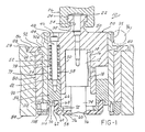
- FIGURE 1 illustrates a punch holder 10 of the rotary indexing type, adapted to accommodate a multitool selection capability.
- the punch holder 10 herein described is houses a single punch 12 of standard configuration.
- the punch 12 includes a shank 14 having a keyway 16 mating with a key 18 fixed to a punch holder member 20.
- the punch holder member 20 comprises a cylindrical member having a tee head portion 22 adapted to be mated with a tee slot 24 formed into a punch ram 26.
- the punch holder member 20 is formed with a cavity 30 slidably fit to the shank 14 of the punch 12, with a capscrew 32 received in counterbore opening 34 extending axially into the upper end of the tee head portion 22 threadably received in the shank 14 to secure the punch 12 therein.
- the punch holder 10 further includes a sleeve 36 slidably fit over the lower end of the holder member 20 to extend below the lower end thereof.
- a quantity of stripper springs 38 are interposed between a radial flange portion 40 of the holder member 20 and the upper end face 42 of the sleeve 36.
- the stripper spring 38 in this case are installed over guide bolts 44 threaded into the upper end face 42 of the sleeve 36.
- the head 46 of the guide bolt 44 is seated on a counterbore 48 extending into the upper end face 50 of the holder member 20.
- the stripper spring 38 is nested into a counterbore 52 recessed into the lower face 54 of the holder member 20.
- the lower end face 56 of the sleeve 36 is enclosed with a cup piece 58 of a plastic material such as a hard urethane.
- the cup piece 58 has a face portion 60 extending across end face 56 of the sleeve 36 and a skirt portion 62 surrounding the adjacent side 64 of the sleeve 36.
- the skirt portion terminates in one or more antirotation tabs 66 received in pockets 68 relieved into a stepped shoulder 70 formed on the sleeve 36.
- the end face 56 is comprised of a radial face having an opening 72 large enough to accommodate the full range of punch sizes to be employed in the punch holder 10.
- the leading end 74 of the punch 12 extends through an opening 76 tightly fit to the punch leading end 74 by virtue of being formed by the punch itself, as will be described herein.
- the holder member 20 and sleeve 36 are positioned in end-to-end alignment within a bore 79 in an indexing sleeve 78 to be axially slidable therein, and conceativieity thereby maintained nested within a bushing 80 seated in a bore 90 formed in the upper turret plate 84 of a punch press.
- the bushing 80 has a flange 86 received in a counterbore 88 portion of a bore 90 machined in the turret 84 to be axially and radially located therein.
- the index sleeve 78 is likewise formed with a flange 90A seated in a counterbore portion 92 of a bore 94.
- the index sleeve 78 is formed with a worm gear 95 driven by a worm 96 for purposes of selecting one of a multitool for multitool holders as described in the aforementioned U.S. patent applications, or to reorient the punch 12.
- FIGURE 2 shows that the assembly of the index sleeve 78, sleeve 36, and holder member 20 are rotationally locked together.
- a key 98 is fastened with screws 100 to the holder member 20, key 98 fit within keyway slot 102 formed in index sleeve 78 to establish said rotational lock while accommodating relative axial movement of the holder member 20.
- Sleeve 36 likewise has a key 104 attached thereto with screws 106, key 104 also fit in keyway slot 102 for the same purpose.
- FIGURE 1 shows that the holder member 20 and sleeve 36 are releasably retained axially within the index sleeve 78 by a peripheral series of spring plunger detents 108 including a plunger 110 engaging a lip 112 on the sleeve 36.
- the stroking of the ram 26 overcomes the retainer force when the punching operation takes place.
- FIGURE 3 shows that the cup piece 58 is provided in blank form 58a without any opening 76 formed in face 60.
- the cup piece blank 58a is initially assembled over the sleeve 36 with a gap 114 therebetween and the punch portion 74 positioned above.
- FIGURE 4 shows that when the press is cycled with a die 77 but without a workpiece, the punch portion 74 will penetrate the face 60 to form the opening 76, and the cup piece 58 will be fully seated on the sleeve 36.
- the ram 26 is stroked downwardly bringing the cup piece 58 against the upper surface of a workpiece. Continuing descent of the ram 26 compresses the cup piece 58 as well as the stripper spring 38 and the punch 12 is advanced through the opening 76 and into the workpiece and die 77.
- the ram 26 is elevated after the completion of its downstroke, raising the punch 12.
- the cup piece 58 remains in position against the workpiece held by the composite force of the compression of the cup piece 58 and the stripper spring 38, enabling withdrawal of the punch portion 74 from the workpiece.
Landscapes
- Engineering & Computer Science (AREA)
- Mechanical Engineering (AREA)
- Punching Or Piercing (AREA)
Claims (10)
- Stanzwerkzeughalter (10) zum Halten eines Stanzwerkzeugs (12) mit einem Schaft (14) und einem von diesem vorstehenden Stanzteil (74), wobei der Stanzwerkzeughalter (10) eine Abstreifvorrichtung hat und ein Halterelement (20) mit einem den Schaft (14) des Stanzwerkzeugs (12) aufnehmenden Hohlraum (30) enthält, mit einem Kopf (22) für den Eingriff in einen Stanzpressenstößel (26), mit einer axial beweglichen inneren Hülse (36), die mit dem Halterelement (20) fluchtet, mit einer Abstreifer-Feder (38), die zwischen dem Halterelement (20) und der Hülse (36) eingesetzt ist und das Halterelement (20) und die Hülse (36) in eine axial voneinander beabstandete Lage drückt, gekennzeichnet durch den Kopf (22) als Teil des Halterelements (20), das den Kopf (22) enthält und den in dem Hohlraum (30) festgelegten Schaft (14) aufnimmt, eine äußere Hülse (78) mit einer Bohrung (79), wobei sowohl das Halterelement (20) als auch die innere Hülse (36) unter dem Halterelement (20) in der Bohrung (79) so bewegbar sind, daß dazwischen eine Konzentrizität bestehen bleibt, und durch ein Napfteil (58) aus einem elastischen Werkstoff, welches das untere Ende (56) der inneren Hülse (36) abdeckt, den vorstehenden Stanzteil (74) aufnimmt und zur Bildung einer Stanzöffnung (76) durch den Hub des Stanzwerkzeugs durchstoßen werden kann.
- Stanzwerkzeughalter (10) nach Anspruch 1, dadurch gekennzeichnet, daß das Napfteil (58) aus Urethankunststoff hergestellt ist.
- Stanzwerkzeughalter (10) nach Anspruch 1 oder 2, dadurch gekennzeichnet, daß die innere Hülse (36) an einem unteren Endbereich des Halterelements (20) verschiebbar befestigt ist, wobei die innere Hülse (36) und das Halterelement (20) voneinander beabstandete, einander gegenüberliegende radiale Stirnflächen (42,54) haben.
- Stanzwerkzeughalter (10) nach Anspruch 3, gekennzeichnet durch ein sich in jede der einander gegenüberliegenden radialen Stirnflächen (42,54) hinein erstreckendes Bolzenelement (44), wobei die Abstreifer-Feder (38) den Bolzen umgibt.
- Stanzwerkzeughalter (10) nach einem der vorhergehenden Ansprüche, dadurch gekennzeichnet, daß die innere Hülse (36) eine radiale Fläche (70) mit darin ausgebildeten Taschen (68) hat, in welche sich Randteile (62) des Napfteils (58) hinein erstrecken.
- Stanzwerkzeughalter (10) nach einem der vorhergehenden Ansprüche, gekennzeichnet durch eine Vorrichtung (78,98,104,102), die das Halterelement (20) und die innere Hülse (36) gegen deren relative Drehung miteinander verriegelt, jedoch deren relative axiale Bewegung zuläßt, damit die Abstreifer-Feder (38) zusammengedrückt werden kann.
- Stanzwerkzeughalter nach Anspruch 6, dadurch gekennzeichnet, daß die äußere Hülse (78) eine Rundschalthülse ist, in welcher die Bohrung (79) ausgebildet ist, in der das Halterelement (20) und die innere Hülse (36) unter Beibehaltung der Konzentrizität zueinander verschiebbar aufgenommen sind.
- Stanzwerkzeughalter (10) nach einem der vorhergehenden Ansprüche, dadurch gekennzeichnet, daß das Napfteil (58) eine Endfläche hat, die sich insgesamt quer zu dem Stanzwerkzeug und unter diesem derart erstreckt, daß sie bei einem ersten Stanzbetriebszyklus des Stößels ohne ein Werkstück durchstoßen wird.
- Stanzwerkzeughalter (10) nach Anspruch 7, gekennzeichnet durch eine Rückhaltevorrichtung (108) in Form von mehreren Rastfedern und einem Kolben, durch welche das Halterelement (20) und die innere Hülse (36) gegen eine axiale Bewegung aus der Schalthülse (78) heraus elastisch nachgebend gehalten sind.
- Stanzwerkzeughalter (10) nach einem der Ansprüche 3 bis 9, dadurch gekennzeichnet, daß die innere Hülse (36) eine Endfläche (56) hat, die radial nach innen von der radial gegenüberliegenden Fläche (42) beabstandet und von dem Napfteil (58) umschlossen ist.
Applications Claiming Priority (2)
| Application Number | Priority Date | Filing Date | Title |
|---|---|---|---|
| US351343 | 1989-05-15 | ||
| US07/351,343 US4993294A (en) | 1989-05-15 | 1989-05-15 | Punch holder with a stripper arrangement |
Publications (2)
| Publication Number | Publication Date |
|---|---|
| EP0398253A1 EP0398253A1 (de) | 1990-11-22 |
| EP0398253B1 true EP0398253B1 (de) | 1993-11-10 |
Family
ID=23380512
Family Applications (1)
| Application Number | Title | Priority Date | Filing Date |
|---|---|---|---|
| EP19900109134 Expired - Lifetime EP0398253B1 (de) | 1989-05-15 | 1990-05-15 | Schneidwerkzeughalter mit Abstreifvorrichtung |
Country Status (5)
| Country | Link |
|---|---|
| US (1) | US4993294A (de) |
| EP (1) | EP0398253B1 (de) |
| JP (1) | JP2658499B2 (de) |
| CA (1) | CA2016723C (de) |
| DE (1) | DE69004486T2 (de) |
Families Citing this family (10)
| Publication number | Priority date | Publication date | Assignee | Title |
|---|---|---|---|---|
| US5056392A (en) * | 1988-08-19 | 1991-10-15 | Mate Punch & Die Co. | Punch assembly |
| US5578482A (en) * | 1990-05-25 | 1996-11-26 | Georgetown University | Ligand growth factors that bind to the erbB-2 receptor protein and induce cellular responses |
| US5176057A (en) * | 1991-10-11 | 1993-01-05 | Murata Machinery Limited | Punch holder with stripper arrangement |
| US5438897A (en) * | 1993-12-29 | 1995-08-08 | Murata Machinery, Ltd., Machine Tool Division | Stripper arrangement for a punch holder |
| JP2895769B2 (ja) | 1994-05-27 | 1999-05-24 | 株式会社アマダメトレックス | パンチング金型 |
| US7024978B1 (en) | 1998-07-10 | 2006-04-11 | International Business Machines Corporation | Concentric alignment device for dies and die stripper |
| US6782787B2 (en) * | 2001-08-02 | 2004-08-31 | Wilson Tool International, Inc. | Adjustable punch having externally accessible rotation release latch |
| WO2006054694A1 (ja) * | 2004-11-19 | 2006-05-26 | Amada Company, Limited | パンチ金型 |
| US9211581B2 (en) * | 2007-09-21 | 2015-12-15 | Wilson Tool International Inc. | Stripper assemblies and components thereof for multi-tool punch assemblies |
| USD742441S1 (en) * | 2013-05-21 | 2015-11-03 | Wilson Tool International Inc. | Punch holder |
Family Cites Families (12)
| Publication number | Priority date | Publication date | Assignee | Title |
|---|---|---|---|---|
| DE1176964B (de) * | 1961-08-30 | 1964-08-27 | Behrens Ag C | Revolverstanze |
| US3540339A (en) * | 1968-01-19 | 1970-11-17 | John S Killaly | Stripper-holddown assembly for punch presses |
| DE1778405B1 (de) * | 1968-04-26 | 1971-11-25 | Hekus Fabrik Fuer Praez Sgerae | Verfahren zum herstellen von passfuehrungen zwischen beweg baren und festen foermteilen |
| US4166403A (en) * | 1977-08-10 | 1979-09-04 | Houdaille Industries, Inc. | Method of making a rigidly supported molded plastics material punch guide and stripper |
| US4222260A (en) * | 1978-05-15 | 1980-09-16 | Wsp Industries Corporation | Warm forging of connecting rod caps |
| DE2939439C2 (de) * | 1979-09-28 | 1982-02-18 | Bayerische Motoren Werke AG, 8000 München | Schnittwerkzeug mit einer Abführeinrichtung für Schnitteile |
| US4440052A (en) * | 1980-09-12 | 1984-04-03 | Unipunch Products, Inc. | Punch assembly with unitary stripper spring assembly |
| AU555957B2 (en) * | 1981-10-20 | 1986-10-16 | Amada Company Limited | Turret punch press |
| US4516449A (en) * | 1982-04-01 | 1985-05-14 | Boyette Bobby R | Tool holder with work release mechanism |
| US4428262A (en) * | 1982-07-09 | 1984-01-31 | Vlahek Charles D | Adjustable long life stripper |
| JPS6042413U (ja) * | 1983-08-31 | 1985-03-26 | 株式会社 アマダ | パンチ組立体 |
| JPS6390535U (de) * | 1986-12-02 | 1988-06-11 |
-
1989
- 1989-05-15 US US07/351,343 patent/US4993294A/en not_active Expired - Lifetime
-
1990
- 1990-05-14 CA CA002016723A patent/CA2016723C/en not_active Expired - Fee Related
- 1990-05-15 DE DE90109134T patent/DE69004486T2/de not_active Expired - Fee Related
- 1990-05-15 JP JP2123253A patent/JP2658499B2/ja not_active Expired - Lifetime
- 1990-05-15 EP EP19900109134 patent/EP0398253B1/de not_active Expired - Lifetime
Also Published As
| Publication number | Publication date |
|---|---|
| DE69004486D1 (de) | 1993-12-16 |
| JPH0390224A (ja) | 1991-04-16 |
| EP0398253A1 (de) | 1990-11-22 |
| JP2658499B2 (ja) | 1997-09-30 |
| US4993294A (en) | 1991-02-19 |
| DE69004486T2 (de) | 1994-05-11 |
| CA2016723A1 (en) | 1990-11-15 |
| CA2016723C (en) | 1999-04-27 |
Similar Documents
| Publication | Publication Date | Title |
|---|---|---|
| US4543701A (en) | Method of attaching a fastener to a panel | |
| US7168356B2 (en) | Adjustable length punch assembly | |
| EP0398253B1 (de) | Schneidwerkzeughalter mit Abstreifvorrichtung | |
| EP0541959B1 (de) | Schneidwerkzeughalter mit Abstreifvorrichtung | |
| US6152005A (en) | Method of punching a punch guide hole in a blank holder of a punch assembly a punch assembly and a blank holder | |
| JP2661329B2 (ja) | マルチツールパンチホルダ | |
| US5054347A (en) | Punch assembly with improved disassembly features | |
| AU2002256179A1 (en) | Adjustable length punch assembly | |
| EP0399339B1 (de) | Markierungswerkzeughalter für eine Stanzpresse | |
| US4257292A (en) | Piercing units | |
| US4998958A (en) | Multitool punch holder | |
| EP0802838A1 (de) | Werkstück verformendes werkzeug in einer stanzpresse | |
| US3848496A (en) | Die and spring assemblies having particular application to stripper plates | |
| US3540339A (en) | Stripper-holddown assembly for punch presses | |
| US5438897A (en) | Stripper arrangement for a punch holder | |
| US5382102A (en) | Indexable marking tool for use with a punch press | |
| EP0646427B1 (de) | Abstreifvorrichtung und Stanzzusammenbau mit dieser Vorrichtung | |
| US4316399A (en) | Combined punch retainer and fluid actuated stripper | |
| US4807859A (en) | Die spring retainer | |
| US6311594B1 (en) | Punch guiding apparatus and stripper plate used therefor | |
| US3938794A (en) | Caged spring unit | |
| EP0399337B1 (de) | Mehrfachwerkzeughalter für Stanzstempel | |
| US3965784A (en) | Blanking die and holder construction for punch presses | |
| SU1641486A1 (ru) | Штамп дл получени полых деталей | |
| EP0605978A2 (de) | Werkzeug zum Formen von Dosendeckel unterschiedlicher Durchmesser |
Legal Events
| Date | Code | Title | Description |
|---|---|---|---|
| PUAI | Public reference made under article 153(3) epc to a published international application that has entered the european phase |
Free format text: ORIGINAL CODE: 0009012 |
|
| AK | Designated contracting states |
Kind code of ref document: A1 Designated state(s): AT BE CH DE DK ES FR GB GR IT LI LU NL SE |
|
| RBV | Designated contracting states (corrected) |
Designated state(s): CH DE FR GB IT LI |
|
| RAP1 | Party data changed (applicant data changed or rights of an application transferred) |
Owner name: MURATA MACHINERY LTD. |
|
| 17P | Request for examination filed |
Effective date: 19910426 |
|
| 17Q | First examination report despatched |
Effective date: 19920430 |
|
| GRAA | (expected) grant |
Free format text: ORIGINAL CODE: 0009210 |
|
| AK | Designated contracting states |
Kind code of ref document: B1 Designated state(s): CH DE FR GB IT LI |
|
| REF | Corresponds to: |
Ref document number: 69004486 Country of ref document: DE Date of ref document: 19931216 |
|
| ITF | It: translation for a ep patent filed | ||
| ET | Fr: translation filed | ||
| RAP4 | Party data changed (patent owner data changed or rights of a patent transferred) |
Owner name: MURATA MACHINERY LTD. |
|
| REG | Reference to a national code |
Ref country code: FR Ref legal event code: CA |
|
| PLBE | No opposition filed within time limit |
Free format text: ORIGINAL CODE: 0009261 |
|
| STAA | Information on the status of an ep patent application or granted ep patent |
Free format text: STATUS: NO OPPOSITION FILED WITHIN TIME LIMIT |
|
| 26N | No opposition filed | ||
| REG | Reference to a national code |
Ref country code: GB Ref legal event code: IF02 |
|
| PGFP | Annual fee paid to national office [announced via postgrant information from national office to epo] |
Ref country code: GB Payment date: 20050503 Year of fee payment: 16 |
|
| PGFP | Annual fee paid to national office [announced via postgrant information from national office to epo] |
Ref country code: FR Payment date: 20050519 Year of fee payment: 16 |
|
| PGFP | Annual fee paid to national office [announced via postgrant information from national office to epo] |
Ref country code: CH Payment date: 20050524 Year of fee payment: 16 |
|
| PGFP | Annual fee paid to national office [announced via postgrant information from national office to epo] |
Ref country code: DE Payment date: 20050630 Year of fee payment: 16 |
|
| PG25 | Lapsed in a contracting state [announced via postgrant information from national office to epo] |
Ref country code: GB Free format text: LAPSE BECAUSE OF NON-PAYMENT OF DUE FEES Effective date: 20060515 |
|
| PG25 | Lapsed in a contracting state [announced via postgrant information from national office to epo] |
Ref country code: LI Free format text: LAPSE BECAUSE OF NON-PAYMENT OF DUE FEES Effective date: 20060531 Ref country code: CH Free format text: LAPSE BECAUSE OF NON-PAYMENT OF DUE FEES Effective date: 20060531 |
|
| PGFP | Annual fee paid to national office [announced via postgrant information from national office to epo] |
Ref country code: IT Payment date: 20060531 Year of fee payment: 17 |
|
| PG25 | Lapsed in a contracting state [announced via postgrant information from national office to epo] |
Ref country code: DE Free format text: LAPSE BECAUSE OF NON-PAYMENT OF DUE FEES Effective date: 20061201 |
|
| REG | Reference to a national code |
Ref country code: CH Ref legal event code: PL |
|
| GBPC | Gb: european patent ceased through non-payment of renewal fee |
Effective date: 20060515 |
|
| REG | Reference to a national code |
Ref country code: FR Ref legal event code: ST Effective date: 20070131 |
|
| PG25 | Lapsed in a contracting state [announced via postgrant information from national office to epo] |
Ref country code: FR Free format text: LAPSE BECAUSE OF NON-PAYMENT OF DUE FEES Effective date: 20060531 |
|
| PG25 | Lapsed in a contracting state [announced via postgrant information from national office to epo] |
Ref country code: IT Free format text: LAPSE BECAUSE OF NON-PAYMENT OF DUE FEES Effective date: 20070515 |