EP0398419A2 - Coupleur directif 3dB à 90 degrés, pour une octave en technique microbande et fente - Google Patents
Coupleur directif 3dB à 90 degrés, pour une octave en technique microbande et fente Download PDFInfo
- Publication number
- EP0398419A2 EP0398419A2 EP90201164A EP90201164A EP0398419A2 EP 0398419 A2 EP0398419 A2 EP 0398419A2 EP 90201164 A EP90201164 A EP 90201164A EP 90201164 A EP90201164 A EP 90201164A EP 0398419 A2 EP0398419 A2 EP 0398419A2
- Authority
- EP
- European Patent Office
- Prior art keywords
- directional coupler
- slotline
- degrees
- microstrip lines
- microstrip
- Prior art date
- Legal status (The legal status is an assumption and is not a legal conclusion. Google has not performed a legal analysis and makes no representation as to the accuracy of the status listed.)
- Withdrawn
Links
Images
Classifications
-
- H—ELECTRICITY
- H01—ELECTRIC ELEMENTS
- H01P—WAVEGUIDES; RESONATORS, LINES, OR OTHER DEVICES OF THE WAVEGUIDE TYPE
- H01P5/00—Coupling devices of the waveguide type
- H01P5/12—Coupling devices having more than two ports
- H01P5/16—Conjugate devices, i.e. devices having at least one port decoupled from one other port
- H01P5/18—Conjugate devices, i.e. devices having at least one port decoupled from one other port consisting of two coupled guides, e.g. directional couplers
- H01P5/184—Conjugate devices, i.e. devices having at least one port decoupled from one other port consisting of two coupled guides, e.g. directional couplers the guides being strip lines or microstrips
- H01P5/185—Edge coupled lines
Definitions
- the present invention relates to the field of directional couplers for microwave circuits and more specifically to a one-octave 90 degrees 3dB directional coupler embodied in microstrip and slotline form.
- the normalization impedance is 50 Ohm.
- Directional couplers operating in the frequency range of 2 GHz to 30 GHz are in general obtained by the thin film technique using alumina substrates having standard thicknesses of 25 or 10 mils depending on the frequency range.
- a first example of embodiment of said 90 degrees 3dB directional couplers consists of two parallel lines of microstrip having predetermined spacing. Despite their simplicity these couplers have the drawback that in practice they cannot be embodied on alumina substrates having the above-mentioned standard thicknesses. Indeed, by using a 25 mil substrate the above characteristic even and odd mode impedances could be made with a distance between lines of approximately 8 ⁇ m, which is too small for the present techniques of thin film deposit.
- This coupler is embodied in microstrip form and, compared with the previous one, has the advantage of allowing greater distance between the coupled lines, i.e. 50 ⁇ m with a 25 mil substrate. It is the interdigitated type and includes conductors which appropriately connect together the interdigitated lines.
- a third example of a known type of directional coupler embodied in microstrip and slotline form is the one termed 'de Ronde' from the name of its inventor. A detailed description thereof is given in Gupta's book mentioned above on pages 244-249.
- Said coupler includes microstrip lines coupled together and deposited on one face of a dielectric substrate and some slotlines made in the metallization deposited on the other face of the substrate.
- This coupler radiates electromagnetic power from the breaks, i.e. open circuits, in the slotline.
- the object of the present invention is to overcome the above drawbacks and indicate a 3dB 90 degrees direction coupler for microwave circuits having a one-octave band extension and consisting of two coupled lines embodied in microstrip form and a slotline loop made in the ground plane of the microstrip lines.
- the slotline loop is rectangular and placed at the outer edge of the microstrip. Its purpose is to increase the characteristic even mode impedance and thus provide the required characteristic even and odd mode impedances with more space between the microstrips than without the loop.
- the object of the present invention is a 90 degrees 3dB directional coupler for microwave circuits as described in claim 1.
- Another object of the present invention is a variant of the subject coupler as described in claims 6 to 10.
- the directional coupler in accordance with the invention possesses the basic advantage of being simple to embody even on alumina substrates with thicknesses of 10 or 25 mils. In addition it does not radiate electromagnetic power because the slotline loop has no breaks capable of acting as antennas.
- Another advantage of the coupler which is the object of this invention is that it maintains good operating performance in a one-octave band, which should be considered wide in comparison with the one obtained with known couplers.
- a particular advantage is the high directivity of the coupler due to the fact that it holds the even and odd mode phase velocities equal to one another.
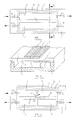
- reference number 1 indicates an alumina dielectric medium on which are deposited two microstrip lines indicated by 2 and 3 respectively. Each end belonging to the lines 2 and 3 is connected to a radiofrequency signal gate. Said gates are indicated by P1, P2, P3 and P4 respectively.
- the microstrip lines 2 and 3 are parallel and separated by an appropriately calculated distance D.
- Two broken lines 4 and 5 delimit the contour of a slotline SL having a closed rectangular shape and made by engraving a metallization plane (indicated by 6 in FIG. 2.) placed on the rear face of the dielectric medium 1.
- FIG. 2 makes clear the exact position of the slotline SL in relation to the microstrips 2 and 3.
- the microstrips 2 and 3 deposited on the top face of the dielectric medium 1, on the bottom face of which is deposited a metallization plane 6 which acts as a ground plane for said microstrips and at the same time includes the slotline loop SL.
- the directional coupler is placed over a metallic medium 7 having a base and four side walls which delimit an empty rectangular interior space 7′.
- the side walls are placed in contact with the metallization plane 6 and enclose the space 7′ to prevent escape of any electromagnetic radiation emitted by the slotline SL.
- a sinusoidal radiofrequency signal at the input to the gate P1 issues from the gates P2 and P3 with a mutual 90 degrees phase shift and an electrical power one-half the input power, said gates P2 and P3 being coupled to the gate P1.
- the directivity mentioned above is a valuable parameter of the directional coupler. It is given by the ratio expressed in dB of the power of the signal present at either of the gates P2 or P3, which are coupled to the gate P1, to the power of the residual signal at the isolated gate P4.
- the coupler which is the object of the invention
- on a 25 mil substrate and with a normalization impedance of 50 Ohm it is appropriate to choose for example a value of 50 ⁇ m for the distance D between the microstrips 2 and 3.
- the width of said microstrips is calculated in such a manner as to obtain a value of 20 Ohm for the odd mode characteristic impedance.
- the value of 50 ⁇ m for the distance D is easily obtained with present thin-film technology.
- the electrical length of the microstrips 2 and 3 is 90 electrical degrees at the central frequency of use.
- the even mode characteristic impedance is only 45 Ohm, thus quite far from the desired value of 120 Ohm.
- the width of the slotline SL it is necessary to calculate the width of the slotline SL so that it will have a characteristic impedance of 75 Ohm. This value is given by the difference between the theoretical value of the even mode characteristic impedance (120 Ohm) of the microstrips 2 and 3 and the value (45 Ohm) which said even mode characteristic impedance would have without the slotline SL.
- a value of 75 Ohm for the characteristic impedance of the slotline SL can be obtained with a width of SL (distance bewtween the broken lines 4 and 5) of approximately 300 ⁇ m.
- FIG. 3 shows a variant of the coupler of FIG. 1 which allows obtaining the isolated gate in a position different from that given in the above example.
- microstrip lines of the same length indicated by numbers 8, 9, 11 and 12.
- the microstrips 8 and 12 are positioned along a first horizontal direction common to both.
- the microstrips 9 and 11 are positioned along a second horizontal direction parallel to the one mentioned above.
- microstrips 8 and 9 located in the centre of the coupler are connected together by a thin section of microstrip line 10 positioned obliquely.
- the ends of the microstrips 11 and 12 located in the centre of the coupler are connected together by a metal wire 13 which is welded to said ends and which bypasses the section of microstrip 10 while remaining isolated therefrom.
- microstrip 8, 12, 11 and 9 are connected in that order to gates indicated by P1′, P2′, P3′ and P4′ positioned in the same manner as the coupler shown in FIG. 1.
- the dielectric medium 1 and the slotline loop SL are indentical to those of the coupler of FIG. 1.
- a sinusoidal radiofrequency signal at the input to the gate P1′ issues from the gates P3′ and P4′, said gates being coupled to the gate P1′ with a mutual 90 degrees phase shift and an electrical power one-half the input power. There is no signal at the gate P2′, said gate being isolated in the variant example.
- a coupler with the above characteristics could be obtained from that of FIG. 1 by crossing together the microstrips and the slotline. But analysis of the structure shows that crossing of the slotline SL has no effect on the operation of the coupler and therefore is not necessary as shown in FIG. 3.
- the distance D separating the microstrips 8, 11 and 9, 12 and the width thereof is calculated as in FIG. 1.
- the electrical length of the microstrips 8, 9 and 10, like that of the microstrips 11, 12 and the wire 13, is 90 electrical degrees to the central frequency of use.
- alumina substrate 25 mils thick In a first embodiment of directional couplers like those shown in the examples of FIGS. 1 and 3 operating in the frequency band from 6GHz to 12GHz there is adopted an alumina substrate 25 mils thick. In a second embodiment of couplers operating in the frequency band from 12GHz to 24GHz there is adopted a substrate 10 mils thick.
- the couplers of both embodiments have the following functions measured over the entire one-octave operating band: - Adaptation to the four gates > 25dB. - Directivity > 25dB. - Unbalance between the coupled gates ⁇ 0.5dB. - Phase shift between coupled gates 90° ⁇ 1°.
Landscapes
- Variable-Direction Aerials And Aerial Arrays (AREA)
Applications Claiming Priority (2)
| Application Number | Priority Date | Filing Date | Title |
|---|---|---|---|
| IT8920508A IT1229726B (it) | 1989-05-15 | 1989-05-15 | Accoppiatore direzionale a 3 db, 90 gradi, un'ottava, realizzato in microstriscia e slotline. |
| IT2050889 | 1989-05-15 |
Publications (2)
| Publication Number | Publication Date |
|---|---|
| EP0398419A2 true EP0398419A2 (fr) | 1990-11-22 |
| EP0398419A3 EP0398419A3 (fr) | 1992-01-08 |
Family
ID=11167995
Family Applications (1)
| Application Number | Title | Priority Date | Filing Date |
|---|---|---|---|
| EP19900201164 Withdrawn EP0398419A3 (fr) | 1989-05-15 | 1990-05-08 | Coupleur directif 3dB à 90 degrés, pour une octave en technique microbande et fente |
Country Status (5)
| Country | Link |
|---|---|
| EP (1) | EP0398419A3 (fr) |
| AU (1) | AU5498690A (fr) |
| IT (1) | IT1229726B (fr) |
| NO (1) | NO902108L (fr) |
| ZA (1) | ZA903701B (fr) |
Cited By (4)
| Publication number | Priority date | Publication date | Assignee | Title |
|---|---|---|---|---|
| US5304959A (en) * | 1992-10-16 | 1994-04-19 | Spectrian, Inc. | Planar microstrip balun |
| US5446425A (en) * | 1993-06-07 | 1995-08-29 | Atr Optical And Radio Communications Research Laboratories | Floating potential conductor coupled quarter-wavelength coupled line type directional coupler comprising cut portion formed in ground plane conductor |
| CN111293395A (zh) * | 2020-03-24 | 2020-06-16 | 北京华镁钛科技有限公司 | 一种基于薄膜介质的小型化耦合器 |
| WO2024124984A1 (fr) * | 2022-12-15 | 2024-06-20 | 合肥华凌股份有限公司 | Coupleur de ligne microruban, module radiofréquence et appareil de non congélation radiofréquence |
Families Citing this family (2)
| Publication number | Priority date | Publication date | Assignee | Title |
|---|---|---|---|---|
| US4983933A (en) * | 1989-10-05 | 1991-01-08 | Sedco Systems Inc. | Waveguide-to-stripline directional coupler |
| IT1251221B (it) * | 1991-07-11 | 1995-05-04 | Sits Soc It Telecom Siemens | Accoppiatore direzionale di tipo ibrido e microonde a costanti concentrate con uscite in quadratura. |
Family Cites Families (2)
| Publication number | Priority date | Publication date | Assignee | Title |
|---|---|---|---|---|
| DD135016A1 (de) * | 1978-03-16 | 1979-04-04 | Aribert Scheffel | Streifenleitungsrichtungskoppler geringer koppeldaempfung |
| SU1195403A1 (ru) * | 1984-06-28 | 1985-11-30 | Предприятие П/Я Г-4273 | Направленный ответвитель |
-
1989
- 1989-05-15 IT IT8920508A patent/IT1229726B/it active
-
1990
- 1990-05-08 EP EP19900201164 patent/EP0398419A3/fr not_active Withdrawn
- 1990-05-11 AU AU54986/90A patent/AU5498690A/en not_active Abandoned
- 1990-05-11 NO NO90902108A patent/NO902108L/no unknown
- 1990-05-15 ZA ZA903701A patent/ZA903701B/xx unknown
Cited By (4)
| Publication number | Priority date | Publication date | Assignee | Title |
|---|---|---|---|---|
| US5304959A (en) * | 1992-10-16 | 1994-04-19 | Spectrian, Inc. | Planar microstrip balun |
| US5446425A (en) * | 1993-06-07 | 1995-08-29 | Atr Optical And Radio Communications Research Laboratories | Floating potential conductor coupled quarter-wavelength coupled line type directional coupler comprising cut portion formed in ground plane conductor |
| CN111293395A (zh) * | 2020-03-24 | 2020-06-16 | 北京华镁钛科技有限公司 | 一种基于薄膜介质的小型化耦合器 |
| WO2024124984A1 (fr) * | 2022-12-15 | 2024-06-20 | 合肥华凌股份有限公司 | Coupleur de ligne microruban, module radiofréquence et appareil de non congélation radiofréquence |
Also Published As
| Publication number | Publication date |
|---|---|
| IT8920508A0 (it) | 1989-05-15 |
| NO902108D0 (no) | 1990-05-11 |
| NO902108L (no) | 1990-11-16 |
| ZA903701B (en) | 1991-02-27 |
| EP0398419A3 (fr) | 1992-01-08 |
| AU5498690A (en) | 1990-11-15 |
| IT1229726B (it) | 1991-09-07 |
Similar Documents
| Publication | Publication Date | Title |
|---|---|---|
| EP0883328B1 (fr) | Plaquette de circuits comprenant une ligne de transmission à haute fréquence | |
| EP1149469B1 (fr) | Coupleur d'impedances a large bande | |
| US4383227A (en) | Suspended microstrip circuit for the propagation of an odd-wave mode | |
| US5303419A (en) | Aperture-coupled line Magic-Tee and mixer formed therefrom | |
| JP2006121643A (ja) | 平面アンテナ | |
| US4211986A (en) | Strip line coupler having spaced ground plate for increased coupling characteristic | |
| US5097233A (en) | Coplanar 3dB quadrature coupler | |
| US6087907A (en) | Transverse electric or quasi-transverse electric mode to waveguide mode transformer | |
| US5777532A (en) | Interdigital slow wave coplanar transmission line | |
| US5281929A (en) | Microstrip twisted broadside coupler apparatus | |
| US12087993B2 (en) | Broadband and low cost printed circuit board based 180° hybrid couplers on a single layer board | |
| EP0417590B1 (fr) | Té magique planaire en forme de ligne à bande à air | |
| CN115207591B (zh) | 强耦合带状线和含有强耦合带状线的微波元件 | |
| GB2170358A (en) | Microwave power divider | |
| CN108321484B (zh) | 90度混合电路 | |
| JP3678194B2 (ja) | 伝送線路および送受信装置 | |
| US20020097108A1 (en) | Transmission line to waveguide mode transformer | |
| JP2000165116A (ja) | 方向性結合器 | |
| CN114421115A (zh) | 一种基于弯折线结构等效电路的宽带定向耦合器 | |
| JP3391271B2 (ja) | 高周波用低損失電極 | |
| GB2096406A (en) | Improvements in or relating to circuits for very high frequency signals including microstrips | |
| US4882555A (en) | Plural plane waveguide coupler | |
| CN218677535U (zh) | 一种无源元件的强耦合带状线结构 | |
| US4438436A (en) | Millimeter wave monopulse comparator circuit | |
| EP0318067B1 (fr) | Circuit hybride à large bande en hyperfréquence avec des sorties en phase ou en opposition de phase |
Legal Events
| Date | Code | Title | Description |
|---|---|---|---|
| PUAI | Public reference made under article 153(3) epc to a published international application that has entered the european phase |
Free format text: ORIGINAL CODE: 0009012 |
|
| AK | Designated contracting states |
Kind code of ref document: A2 Designated state(s): CH DE ES FR GB GR IT LI SE |
|
| PUAL | Search report despatched |
Free format text: ORIGINAL CODE: 0009013 |
|
| AK | Designated contracting states |
Kind code of ref document: A3 Designated state(s): CH DE ES FR GB GR IT LI SE |
|
| STAA | Information on the status of an ep patent application or granted ep patent |
Free format text: STATUS: THE APPLICATION IS DEEMED TO BE WITHDRAWN |
|
| 18D | Application deemed to be withdrawn |
Effective date: 19920609 |