EP0398470A2 - Trägheitsdämpfer - Google Patents
Trägheitsdämpfer Download PDFInfo
- Publication number
- EP0398470A2 EP0398470A2 EP90302695A EP90302695A EP0398470A2 EP 0398470 A2 EP0398470 A2 EP 0398470A2 EP 90302695 A EP90302695 A EP 90302695A EP 90302695 A EP90302695 A EP 90302695A EP 0398470 A2 EP0398470 A2 EP 0398470A2
- Authority
- EP
- European Patent Office
- Prior art keywords
- mount base
- inertia
- gel
- weight element
- inertia weight
- Prior art date
- Legal status (The legal status is an assumption and is not a legal conclusion. Google has not performed a legal analysis and makes no representation as to the accuracy of the status listed.)
- Granted
Links
Images





Classifications
-
- H—ELECTRICITY
- H02—GENERATION; CONVERSION OR DISTRIBUTION OF ELECTRIC POWER
- H02K—DYNAMO-ELECTRIC MACHINES
- H02K15/00—Processes or apparatus specially adapted for manufacturing, assembling, maintaining or repairing of dynamo-electric machines
-
- H—ELECTRICITY
- H02—GENERATION; CONVERSION OR DISTRIBUTION OF ELECTRIC POWER
- H02K—DYNAMO-ELECTRIC MACHINES
- H02K37/00—Motors with rotor rotating step by step and without interrupter or commutator driven by the rotor, e.g. stepping motors
- H02K37/22—Damping units
-
- F—MECHANICAL ENGINEERING; LIGHTING; HEATING; WEAPONS; BLASTING
- F16—ENGINEERING ELEMENTS AND UNITS; GENERAL MEASURES FOR PRODUCING AND MAINTAINING EFFECTIVE FUNCTIONING OF MACHINES OR INSTALLATIONS; THERMAL INSULATION IN GENERAL
- F16F—SPRINGS; SHOCK-ABSORBERS; MEANS FOR DAMPING VIBRATION
- F16F15/00—Suppression of vibrations in systems; Means or arrangements for avoiding or reducing out-of-balance forces, e.g. due to motion
- F16F15/10—Suppression of vibrations in rotating systems by making use of members moving with the system
- F16F15/14—Suppression of vibrations in rotating systems by making use of members moving with the system using masses freely rotating with the system, i.e. uninvolved in transmitting driveline torque, e.g. rotative dynamic dampers
- F16F15/1407—Suppression of vibrations in rotating systems by making use of members moving with the system using masses freely rotating with the system, i.e. uninvolved in transmitting driveline torque, e.g. rotative dynamic dampers the rotation being limited with respect to the driving means
- F16F15/1414—Masses driven by elastic elements
- F16F15/1435—Elastomeric springs, i.e. made of plastic or rubber
- F16F15/1442—Elastomeric springs, i.e. made of plastic or rubber with a single mass
-
- F—MECHANICAL ENGINEERING; LIGHTING; HEATING; WEAPONS; BLASTING
- F16—ENGINEERING ELEMENTS AND UNITS; GENERAL MEASURES FOR PRODUCING AND MAINTAINING EFFECTIVE FUNCTIONING OF MACHINES OR INSTALLATIONS; THERMAL INSULATION IN GENERAL
- F16F—SPRINGS; SHOCK-ABSORBERS; MEANS FOR DAMPING VIBRATION
- F16F15/00—Suppression of vibrations in systems; Means or arrangements for avoiding or reducing out-of-balance forces, e.g. due to motion
- F16F15/10—Suppression of vibrations in rotating systems by making use of members moving with the system
- F16F15/16—Suppression of vibrations in rotating systems by making use of members moving with the system using a fluid or pasty material
- F16F15/167—Suppression of vibrations in rotating systems by making use of members moving with the system using a fluid or pasty material having an inertia member, e.g. ring
- F16F15/173—Suppression of vibrations in rotating systems by making use of members moving with the system using a fluid or pasty material having an inertia member, e.g. ring provided within a closed housing
-
- H—ELECTRICITY
- H02—GENERATION; CONVERSION OR DISTRIBUTION OF ELECTRIC POWER
- H02K—DYNAMO-ELECTRIC MACHINES
- H02K7/00—Arrangements for handling mechanical energy structurally associated with dynamo-electric machines, e.g. structural association with mechanical driving motors or auxiliary dynamo-electric machines
Definitions
- an inertia damper comprising a mount base, an inertia weight element and a gel element, said mount base and inertia weight element being coupled to each other through said gel element in a vibration absorbing manner, wherein said mount base is formed on the outer periphery thereof with a peripheral cover section to define a housing space therein for receiving said inertia weight element, and said gel element is interposed between the outer peripheral surface of said inertia weight element and the inner peripheral surface of said peripheral cover section to couple said inertia weight element and mount base to each other in a vibration absorbing manner.
- Fig. 2 shows a stepping motor on which an embodiment of an inertia damper according to the present invention is mounted
- Fig. 3 shows an inertia damper of the embodiment, wherein an inertia damper and a stepping motor are designated by reference numerals 20 and 22, respectively.
- the inertia damper 20 is mounted on one side of the stepping motor 22 and arranged substantially coaxial with a drive shaft 24 provided on the other side of the stepping motor 22 so as to outwardly extend therefrom. More specifically, the inertia damper 20 is mounted on a mounting shaft 26 of the stepping motor 22 provided on the one side thereof so as to outwardly extend therefrom substantially coaxial with the drive shaft 24.
- the group R1 at each terminal of the molecule is a monovalent hydrocarbon group free of any unsaturated aliphatic bonds and includes, for example, an alkyl group such as a methyl group, a propyl group or a hexyl group, a phenyl group, a fluoroalkyl group and the like.
- the components A and B are mixed together in such amounts that the molar ratio of the total amount of alkenyl groups on the silicon atoms of the component A to the total mount of hydrogen atoms directly bonded to the silicon atoms of the component B is in the range of 0.1 to 0.2 and preferably 0.1 to 1.0. Then, the so-obtained mixture is cured by a curing reaction, leading to the silicone gel.
- the curing reaction may be carried out in the presence of a platinum catalyst.
- the platinum catalyst used for this purpose includes, for example, finely divided elemental platinum, chloroplatinic acid, platinum chloride, complex salts of olefin with platinum, platinum alcoholate and complex salts of vinylsiloxane with chloroplatinic acid.
- Such a platinum catalyst may be generally used in an amount of 0.1 ppm or more, in terms of elemental platinum, based on the total amount of the components A and B and preferably 0.5 ppm or more.
- the amont of platinum catalyst does not have any specific upper limit; however, if the catalyst is in the form of liquid or in the form of solution, good results may be obtained when the catalyst is used in an amount of 200 ppm or less.
- silicone adhesive of the addition reaction type may be applied after the silicone primer is coated, resulting in the bonding being more effectively carried out.
- a silicone adhesive which performs addition reaction with the silicone gel by heating to cure the silicone gel may be used as such a silicone adhesive of the addition reaction type.
- the silicone adhesive used includes, for example, KE-1800T commercially available from Shin-Etsu Kagaku Kabushiki Kaisha, Japen, SE-1700 commercially available from Taray Silicone Kabushiki Kaisha, Japan and the like.
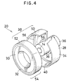
- Fig. 4 shows another embodiment of an inertia damper according to the present invention.
- a peripheral cover section 38 is constructed in a two-layer structure. More particularly, in the illustrated embodiment, the peripheral cover section 38 includes an outer cover plate 50 formed integral with a holding member 34 of a mount base 28 and an inner sleeve 52 formed separate from the outer cover plate 50 and tightly fitted in the outer cover plate 50.
- Fig. 5 shows a further embodiment of an inertia damper according to the present invention.
- the surfaces of a holding member 34 and an inertia weight element 30 opposite to each other and more particularly the inner peripheral surface of a peripheral cover section 38 and the outer peripheral surface of the inertia weight element 30 are formed thereon with a plurality of projections 58a and 58b, resulting in being formed into, for example, a corrugated shape.
- Such construction causes a gel element 32 to be formed in a zigzag or corrugated manner, so that the inertia damper may exhibit damping characteristics different from the embodiments described above.
- the remaining part of the embodiment may be constructed in substantially the same manner as the embodiment shown in Fig. 2.
- the boss 36 is held in place in a plastic mold 100 and then a molten plastic resin material forming the holding material 36 such as, for example, polyester, nylon, polyacetal or the like is injected or poured into the mold 100.
- the plastic resin material is likewise used for forming the inner sleeve 52 separate from the outer cover plate 50 and constituting the peripheral cover section 38 in cooperation with the plate 50 and a lid 48.
- the boss 36 is formed on the outer peripheral surface thereof with unevenness such as knurl, serration or the like. Such unevenness ensures fixed engagement by bite between a boss fit-in section of the holding member 34 and the boss 36.
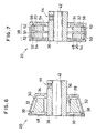
- a lid-side low-friction plate 64 is arranged on the inner surface of the lid 48, as shown in Figs. 8 and 9.
- the inertia weight element 30 and inner sleeve 52 are assembled integrally in the mount base 28.
- integral assembling is desirable because of improving the manufacturing efficiency and safely protecting a gel element 32 which substantially affects the performance of the inertia damper.
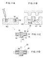
- a unit 54 (Fig. 9A) is previously formed which comprises the inertia weight element 30, inner sleeve 52 and gel element 32 formed between the inertia weight element 30 and the sleeve 52, for example, as shown in Fig. 11A.
- the inertia weight element 30 and inner sleeve 52 are held sideways by means of a jig 102 and a gel material for the gel element 32 is poured into the gap between the element 30 and the sleeve 52, resulting in the unit being formed.
- the unit 54 is incorporated into the holding member 34 integrally coupled to the boss 36, as shown in Fig. 11C.
- the unit 54 comprising the inertia weight element 30, gel element 32 and inner sleeve 52 is pressedly fitted in the holding member 34. This causes the inner peripheral surface of the outer cover plate 50 to be contacted with the outer peripheral surface of the inner sleeve 52.
- the lid 48 is mounted on the open end of the mount base 28 to sealedly close it.
- the lid 48 is formed at the portion of the inner surface thereof positioned somewhat inside from the outer periphery thereof with a fit-in rib 66, which serves to accurately position the lid 48 with respect to the holding member 34 and accurately position the inner sleeve 52 in a housing space defined in the holding member 34.
- the outer periphery of the holding member 34 and the lid 48 are heated by internal heating techniques such as ultrasonic heating or the like to carry out welding between the outer cover plate 50 and the inner sleve 52 and welding between the inner sleeve 52 and the lid 48, as well as welding between the lid 48 and the distal end of the boss fit-in section 60 of the holding member 34, as shown in Fig. 11D.
- the holding member 34, inner sleeve 52 and lid 48 may be fixed to one another.
- the peripheral cover section 38 of the holding member 34 is provided at the free end thereof with at least one recess 68 and positionally correspondingly the inner sleeve 52 is provided at the free end thereof with at least one recess 70.
- the lid 48 is provided on the inner surface thereof with at least one projection 72 engaged with the recess 70 of the inner sleeve 52 in a manner to positionally correspond to the recesses 70, as well as at least one projection 74 engaged with the recess 68 of the peripheral cover section 38.
- each four such recesses 68 and 70 and projections 72 and 74 are formed. The arrangement of such recesses and projections permits rigid fixing among the holding member 34, inner sleeve 52 and lid 48 to be carried out because of securely positioning these members with respect to one another.
- the inertia damper of each of the embodiments described above may be mounted on, for example, a stepping motor, as shown in Fig. 2. Vibration or the like transiently produced from the stepping motor 22 when it is started is effectively absorbed by the cooperation between the inertia weight element and the gel element, so that the vibration may be rapidly extinguished and the stepping motor 22 may be stably increased in rotational speed while being prevented from being stopped due to resonance at an intermediate frequency.
- the inertia damper of the present invention is so constructed that in the combination of the inertia weight element directly carrying out a damping action and the gel element, the gel element is interposedly arranged between the outer periphery of the inertia weight element and the inner surface of the peripheral cover section of the holding member.
- Such construction permits the area of arrangement of the gel element to be increased to reduce loading per unit area of the gel element, resulting the inertia damper of the present invention exhibiting much satisfactory endurance as compared with such a conventional inertia damper as shown in Fig. 1. This will be readily understood from the following Table showing results of a comparison test.
- the inertia damper of the present invention may be so constructed that the peripheral cover section is covered with the lid to keep the housing space closed. Such construction effectively prevents entrance of dust or the like into the inertia damper and leakage of volatiles of the gel element to the exterior of the damper.
- the arrangement of the positioning or engagement means on the lid, holding member and inner sleeve leads to rigid and accurate fixing therebetween.
- the friction reducing means may be provided between the mount base and the inertia weight element and/or between the lid and the inertia weight element. This effectively prevents each of these members from being damaged due to friction therebetween.
Landscapes
- Engineering & Computer Science (AREA)
- General Engineering & Computer Science (AREA)
- Power Engineering (AREA)
- Physics & Mathematics (AREA)
- Acoustics & Sound (AREA)
- Aviation & Aerospace Engineering (AREA)
- Mechanical Engineering (AREA)
- Manufacturing & Machinery (AREA)
- Vibration Dampers (AREA)
- Combined Devices Of Dampers And Springs (AREA)
- Vibration Prevention Devices (AREA)
- Connection Of Motors, Electrical Generators, Mechanical Devices, And The Like (AREA)
Applications Claiming Priority (2)
| Application Number | Priority Date | Filing Date | Title |
|---|---|---|---|
| JP61365/89 | 1989-03-14 | ||
| JP1061365A JPH02240440A (ja) | 1989-03-14 | 1989-03-14 | 慣性ダンパ |
Publications (3)
| Publication Number | Publication Date |
|---|---|
| EP0398470A2 true EP0398470A2 (de) | 1990-11-22 |
| EP0398470A3 EP0398470A3 (de) | 1991-10-02 |
| EP0398470B1 EP0398470B1 (de) | 1994-11-23 |
Family
ID=13169065
Family Applications (1)
| Application Number | Title | Priority Date | Filing Date |
|---|---|---|---|
| EP90302695A Expired - Lifetime EP0398470B1 (de) | 1989-03-14 | 1990-03-14 | Trägheitsdämpfer |
Country Status (5)
| Country | Link |
|---|---|
| US (1) | US6536567B2 (de) |
| EP (1) | EP0398470B1 (de) |
| JP (1) | JPH02240440A (de) |
| KR (1) | KR920010956B1 (de) |
| DE (1) | DE69014232T2 (de) |
Cited By (1)
| Publication number | Priority date | Publication date | Assignee | Title |
|---|---|---|---|---|
| EP1176337A4 (de) * | 2000-01-14 | 2005-07-20 | Fukoku Kk | Dämpfer und herstellungsmethode dafür |
Families Citing this family (16)
| Publication number | Priority date | Publication date | Assignee | Title |
|---|---|---|---|---|
| US6705946B2 (en) * | 2001-06-18 | 2004-03-16 | Honeywell International, Inc. | Oil-less shaft coupling utilizing carbon-carbon composite and method of fabrication thereof |
| JP4421500B2 (ja) * | 2005-03-23 | 2010-02-24 | 倉敷化工株式会社 | 防振装置 |
| JP4922775B2 (ja) * | 2007-01-29 | 2012-04-25 | 株式会社フジキン | 流体制御器 |
| US8468813B2 (en) * | 2007-03-16 | 2013-06-25 | Tenneco Automotive Operating Company Inc. | Snap-action valve for exhaust system |
| EP2140174B1 (de) * | 2007-04-18 | 2011-06-29 | Neumayer Tekfor Holding GMBH | Zahnrad |
| US8381401B2 (en) * | 2009-04-16 | 2013-02-26 | Tenneco Automotive Operating Company Inc. | Method of installing rotatable flapper valve to an interior of a conduit |
| US8191572B2 (en) * | 2009-04-16 | 2012-06-05 | Tenneco Automotive Operating Company Inc. | Snap action valve with bumper pad |
| US7896130B2 (en) * | 2009-05-22 | 2011-03-01 | Tenneco Automotive Operating Company Inc. | Snap action valve with inertia damper |
| EP2714709B1 (de) | 2011-05-26 | 2018-04-18 | University of Washington | Zusammensetzung zur verwendung in einem zellen- und genbasierten verfahren zur verbesserung der herzfunktion |
| US8657065B1 (en) | 2012-12-14 | 2014-02-25 | Tenneco Automotive Operating Company Inc. | Exhaust valve with resilient spring pad |
| US20140239752A1 (en) * | 2013-02-25 | 2014-08-28 | Kollmorgen Corporation | Stepper Motor Rotor with Internal Damper |
| EP2824362B2 (de) * | 2013-07-12 | 2019-03-06 | Vibracoustic GmbH | Drehschwingungsdämpfer |
| DE102017114491A1 (de) * | 2017-06-29 | 2019-01-03 | Schaeffler Technologies AG & Co. KG | Getriebewelle sowie Kraftfahrzeuggetriebe |
| JP2021173363A (ja) * | 2020-04-28 | 2021-11-01 | 日本電産サンキョー株式会社 | ダンパー部材およびアクチュエータ |
| US11877646B2 (en) | 2021-07-12 | 2024-01-23 | Knoll, Inc. | Work surface attachment mechanism, article of furniture, and method of making the article of furniture |
| CN115892462A (zh) * | 2022-11-18 | 2023-04-04 | 中国直升机设计研究所 | 一种桨叶静平衡配重结构 |
Family Cites Families (15)
| Publication number | Priority date | Publication date | Assignee | Title |
|---|---|---|---|---|
| GB1236582A (en) | 1967-08-15 | 1971-06-23 | Holset Engineering Co | Viscous torsional vibration damper |
| US3545301A (en) | 1969-06-02 | 1970-12-08 | Cincinnati Milacron Inc | Stepping motor damper |
| US3552230A (en) | 1970-03-11 | 1971-01-05 | Houdaille Industries Inc | Optimumly tuned and efficient viscous dampers |
| US3790831A (en) | 1972-06-09 | 1974-02-05 | Computer Devices | Apparatus for damping oscillations in a stepping motor |
| AU504982B2 (en) | 1975-06-18 | 1979-11-01 | Vdo Adolf Schindling Aktiengesellschaft | Damping device for a stepping motor |
| JPS5260913A (en) | 1975-11-14 | 1977-05-19 | Hitachi Ltd | Vibration-proof motor |
| DE2922585B1 (de) | 1979-06-02 | 1980-12-11 | Krupp Ag Huettenwerke | Schwingungsabsorber fuer Resonanzschwingungen rotierender Koerper |
| GB2068503B (en) | 1980-01-25 | 1983-07-06 | Concentric Pumps Ltd | Vibration dampers |
| US4563605A (en) | 1984-07-10 | 1986-01-07 | Gerber Scientific Inc. | Damping device for rotary stepping motor |
| JPS6213839A (ja) * | 1985-07-10 | 1987-01-22 | Kiyuubitsuku Eng:Kk | 振動吸収部材の製造方法 |
| EP0229013A3 (de) | 1986-01-09 | 1989-05-10 | Shinko Electric Co. Ltd. | Vorrichtung zur Schwingungsdämpfung für einen Schrittmotor |
| US4800306A (en) | 1986-05-19 | 1989-01-24 | Ing. C. Olivetti & C., S.P.A. | Device for damping the oscillations of a stepping motor |
| JPS6483946A (en) | 1987-09-26 | 1989-03-29 | Cubic Eng Kk | Inertia damper |
| US4825983A (en) | 1987-03-14 | 1989-05-02 | Motoyasu Nakanishi | Inertia damper |
| JPH01227651A (ja) | 1988-03-04 | 1989-09-11 | Kiyuubitsuku Eng:Kk | 慣性ダンパ |
-
1989
- 1989-03-14 JP JP1061365A patent/JPH02240440A/ja active Pending
-
1990
- 1990-03-14 DE DE69014232T patent/DE69014232T2/de not_active Expired - Fee Related
- 1990-03-14 KR KR9003404A patent/KR920010956B1/ko not_active Expired
- 1990-03-14 EP EP90302695A patent/EP0398470B1/de not_active Expired - Lifetime
-
2001
- 2001-03-26 US US09/816,153 patent/US6536567B2/en not_active Expired - Fee Related
Cited By (3)
| Publication number | Priority date | Publication date | Assignee | Title |
|---|---|---|---|---|
| EP1176337A4 (de) * | 2000-01-14 | 2005-07-20 | Fukoku Kk | Dämpfer und herstellungsmethode dafür |
| US6984432B2 (en) | 2000-01-14 | 2006-01-10 | Fukoku Co., Ltd. | Damper and process thereof |
| US7354637B2 (en) | 2000-01-14 | 2008-04-08 | Fukoku Co., Ltd. | Damper and process thereof |
Also Published As
| Publication number | Publication date |
|---|---|
| EP0398470B1 (de) | 1994-11-23 |
| US20020043438A1 (en) | 2002-04-18 |
| KR900015414A (ko) | 1990-10-26 |
| DE69014232D1 (de) | 1995-01-05 |
| KR920010956B1 (en) | 1992-12-24 |
| EP0398470A3 (de) | 1991-10-02 |
| DE69014232T2 (de) | 1995-04-06 |
| US6536567B2 (en) | 2003-03-25 |
| JPH02240440A (ja) | 1990-09-25 |
Similar Documents
| Publication | Publication Date | Title |
|---|---|---|
| EP0398470B1 (de) | Trägheitsdämpfer | |
| US6512314B1 (en) | Stepping motor having characteristics of an inertia damper | |
| EP0283234B1 (de) | Trägheitsdämpfer | |
| EP0381198B1 (de) | Gerät, das eine Flüssigkeit verwendet, deren Viskosität sich unter Stromzufuhr ändert | |
| JP5444514B1 (ja) | シート状シール材及び積層シート状シール材 | |
| US4720431A (en) | Silicone encapsulated devices | |
| JP2021051905A (ja) | シーリング材用熱伝導シート及びこれを組み込んだ発熱性電気・電子部品 | |
| KR102024524B1 (ko) | 전기자동차 배터리 팩용 방열패키지 제조방법과 이에 의해 제조된 배터리 팩용 방열 패키지 | |
| JP2632230B2 (ja) | 慣性ダンパ | |
| KR100855228B1 (ko) | 표면개질 코런덤 및 수지조성물 | |
| EP0509515A1 (de) | Härtbare Organopolysiloxan-Gelzusammensetzung | |
| US4982599A (en) | Acceleration detector | |
| US7359201B2 (en) | Heat-generating electronic part cover and cover mounting method | |
| JP2967232B2 (ja) | 精密機器等における防振構造 | |
| JP2024159930A (ja) | アクチュエータ | |
| JP2014001362A (ja) | 太陽電池モジュール | |
| JPH05159552A (ja) | インシュレータ | |
| KR20250073364A (ko) | 배터리 모듈용 실리콘 기반 단열재 | |
| GB2265497A (en) | Electronic unit, particularly for controlling functions of an internal combustion engine | |
| JPS5817504B2 (ja) | 防振材 | |
| JP2863799B2 (ja) | 剪断歪型シリコーンゲルインシュレータ | |
| RU2135535C1 (ru) | Полиорганосилоксановая композиция | |
| JPH02118224A (ja) | 遮熱板付き防振ブッシュ | |
| JPH05100061A (ja) | ハードデイスクドライブにおけるスイングアームの防振構造 | |
| JPH03139565A (ja) | 硬化性オルガノポリシロキサンゲル組成物 |
Legal Events
| Date | Code | Title | Description |
|---|---|---|---|
| PUAI | Public reference made under article 153(3) epc to a published international application that has entered the european phase |
Free format text: ORIGINAL CODE: 0009012 |
|
| AK | Designated contracting states |
Kind code of ref document: A2 Designated state(s): AT BE CH DE DK ES FR GB GR IT LI LU NL SE |
|
| PUAL | Search report despatched |
Free format text: ORIGINAL CODE: 0009013 |
|
| AK | Designated contracting states |
Kind code of ref document: A3 Designated state(s): AT BE CH DE DK ES FR GB GR IT LI LU NL SE |
|
| RBV | Designated contracting states (corrected) |
Designated state(s): DE FR GB IT NL |
|
| 17P | Request for examination filed |
Effective date: 19920320 |
|
| 17Q | First examination report despatched |
Effective date: 19930716 |
|
| GRAA | (expected) grant |
Free format text: ORIGINAL CODE: 0009210 |
|
| AK | Designated contracting states |
Kind code of ref document: B1 Designated state(s): DE FR GB IT NL |
|
| REF | Corresponds to: |
Ref document number: 69014232 Country of ref document: DE Date of ref document: 19950105 |
|
| ET | Fr: translation filed | ||
| ITF | It: translation for a ep patent filed | ||
| PLBE | No opposition filed within time limit |
Free format text: ORIGINAL CODE: 0009261 |
|
| STAA | Information on the status of an ep patent application or granted ep patent |
Free format text: STATUS: NO OPPOSITION FILED WITHIN TIME LIMIT |
|
| 26N | No opposition filed | ||
| PGFP | Annual fee paid to national office [announced via postgrant information from national office to epo] |
Ref country code: DE Payment date: 20010306 Year of fee payment: 12 |
|
| PGFP | Annual fee paid to national office [announced via postgrant information from national office to epo] |
Ref country code: FR Payment date: 20010313 Year of fee payment: 12 |
|
| PGFP | Annual fee paid to national office [announced via postgrant information from national office to epo] |
Ref country code: GB Payment date: 20010314 Year of fee payment: 12 |
|
| PGFP | Annual fee paid to national office [announced via postgrant information from national office to epo] |
Ref country code: NL Payment date: 20010330 Year of fee payment: 12 |
|
| REG | Reference to a national code |
Ref country code: GB Ref legal event code: IF02 |
|
| PG25 | Lapsed in a contracting state [announced via postgrant information from national office to epo] |
Ref country code: GB Free format text: LAPSE BECAUSE OF NON-PAYMENT OF DUE FEES Effective date: 20020314 |
|
| PG25 | Lapsed in a contracting state [announced via postgrant information from national office to epo] |
Ref country code: NL Free format text: LAPSE BECAUSE OF NON-PAYMENT OF DUE FEES Effective date: 20021001 Ref country code: DE Free format text: LAPSE BECAUSE OF NON-PAYMENT OF DUE FEES Effective date: 20021001 |
|
| GBPC | Gb: european patent ceased through non-payment of renewal fee |
Effective date: 20020314 |
|
| PG25 | Lapsed in a contracting state [announced via postgrant information from national office to epo] |
Ref country code: FR Free format text: LAPSE BECAUSE OF NON-PAYMENT OF DUE FEES Effective date: 20021129 |
|
| NLV4 | Nl: lapsed or anulled due to non-payment of the annual fee |
Effective date: 20021001 |
|
| REG | Reference to a national code |
Ref country code: FR Ref legal event code: ST |
|
| PG25 | Lapsed in a contracting state [announced via postgrant information from national office to epo] |
Ref country code: IT Free format text: LAPSE BECAUSE OF NON-PAYMENT OF DUE FEES;WARNING: LAPSES OF ITALIAN PATENTS WITH EFFECTIVE DATE BEFORE 2007 MAY HAVE OCCURRED AT ANY TIME BEFORE 2007. THE CORRECT EFFECTIVE DATE MAY BE DIFFERENT FROM THE ONE RECORDED. Effective date: 20050314 |