EP0398471A1 - Jonction articulée pour tuyaux - Google Patents
Jonction articulée pour tuyaux Download PDFInfo
- Publication number
- EP0398471A1 EP0398471A1 EP90302865A EP90302865A EP0398471A1 EP 0398471 A1 EP0398471 A1 EP 0398471A1 EP 90302865 A EP90302865 A EP 90302865A EP 90302865 A EP90302865 A EP 90302865A EP 0398471 A1 EP0398471 A1 EP 0398471A1
- Authority
- EP
- European Patent Office
- Prior art keywords
- hook
- lugs
- axle
- segments
- segment
- Prior art date
- Legal status (The legal status is an assumption and is not a legal conclusion. Google has not performed a legal analysis and makes no representation as to the accuracy of the status listed.)
- Granted
Links
- 230000008878 coupling Effects 0.000 title claims abstract description 82
- 238000010168 coupling process Methods 0.000 title claims abstract description 82
- 238000005859 coupling reaction Methods 0.000 title claims abstract description 82
- 230000005484 gravity Effects 0.000 claims abstract description 16
- 238000007789 sealing Methods 0.000 claims description 7
- 230000037431 insertion Effects 0.000 claims 1
- 238000003780 insertion Methods 0.000 claims 1
- 238000000926 separation method Methods 0.000 claims 1
- 238000010276 construction Methods 0.000 description 5
- 150000001875 compounds Chemical class 0.000 description 2
- 229910001018 Cast iron Inorganic materials 0.000 description 1
- 239000012530 fluid Substances 0.000 description 1
- 238000009434 installation Methods 0.000 description 1
- 239000002184 metal Substances 0.000 description 1
- 229910052751 metal Inorganic materials 0.000 description 1
- 238000005058 metal casting Methods 0.000 description 1
- 238000000034 method Methods 0.000 description 1
- 230000004048 modification Effects 0.000 description 1
- 238000012986 modification Methods 0.000 description 1
- 238000002360 preparation method Methods 0.000 description 1
Images
Classifications
-
- F—MECHANICAL ENGINEERING; LIGHTING; HEATING; WEAPONS; BLASTING
- F16—ENGINEERING ELEMENTS AND UNITS; GENERAL MEASURES FOR PRODUCING AND MAINTAINING EFFECTIVE FUNCTIONING OF MACHINES OR INSTALLATIONS; THERMAL INSULATION IN GENERAL
- F16L—PIPES; JOINTS OR FITTINGS FOR PIPES; SUPPORTS FOR PIPES, CABLES OR PROTECTIVE TUBING; MEANS FOR THERMAL INSULATION IN GENERAL
- F16L17/00—Joints with packing adapted to sealing by fluid pressure
- F16L17/02—Joints with packing adapted to sealing by fluid pressure with sealing rings arranged between outer surface of pipe and inner surface of sleeve or socket
- F16L17/04—Joints with packing adapted to sealing by fluid pressure with sealing rings arranged between outer surface of pipe and inner surface of sleeve or socket with longitudinally split or divided sleeve
-
- Y—GENERAL TAGGING OF NEW TECHNOLOGICAL DEVELOPMENTS; GENERAL TAGGING OF CROSS-SECTIONAL TECHNOLOGIES SPANNING OVER SEVERAL SECTIONS OF THE IPC; TECHNICAL SUBJECTS COVERED BY FORMER USPC CROSS-REFERENCE ART COLLECTIONS [XRACs] AND DIGESTS
- Y10—TECHNICAL SUBJECTS COVERED BY FORMER USPC
- Y10T—TECHNICAL SUBJECTS COVERED BY FORMER US CLASSIFICATION
- Y10T24/00—Buckles, buttons, clasps, etc.
- Y10T24/14—Bale and package ties, hose clamps
- Y10T24/1412—Bale and package ties, hose clamps with tighteners
- Y10T24/1441—Tangential screw
- Y10T24/1451—Plural separable parts
Definitions
- This invention relates to an improved pipe coupling of the type which is formed of arcuate segments that provide a circular housing which encircle and connect pipes together.
- a typical coupling, of the type involved is formed of a pair of semi-circular segments which have radially outwardly extending lugs formed on their opposite ends. The lugs of one segment overlap and are aligned with the lugs of the adjacent segment. The pairs of overlapped lugs are fastened together with bolts and nuts or the like mechanical fasteners.
- the housing formed by the alignment segments is typically U-shaped in cross-section to form a radially inwardly opening, continuous channel.
- a rubber-like gasket is inserted within the channel.
- the gasket encircles and seals against the adjacent edges of the two pipe ends to be connected.
- the legs of the housing channel may be directly engaged against the pipe surfaces or within grooves formed in the pipe surfaces for fastening the coupling to the pipes.
- This invention contemplates a coupling formed of a number of arcuate segments, such as two, three or four segments, which are hingedly connected together, with the exception that adjacent ends of the first and last of the pairs of segments are fastened together with a manually applied mechanical fastener, such as a bolt.
- a plumber may position, and hold, a first segment upon a pair of adjacent pipe ends, while permitting the remaining segments to freely dangle beneath the positioned segment ready for application.
- one of his hands is free for use in completing the coupling work, such as positioning the necessary sealing gasket or the like.
- the plumber may use his free hand to pivot the dangling segments into their positions around the pipe and to complete the coupling by inserting the bold through the aligned ends of the first and last segments.
- Integral, outwardly extending, lugs are formed on the opposite ends of each of the segments.
- the adjacent overlapping pairs of lugs are interconnected by a curved hook formed on one lug and an opening, which provides a hook receiving axle, formed on the other lug.
- the segments form a chain of segments joined together by hook and axle connections, so that the first segment may be manually held on a pipe end while the remaining segments dangle beneath.
- Each hook and the opening through which each hook extends over the hook axle portion is formed so that the hook is slightly over center, relative to a vertical plane through the axle. Consequently, when its segment is freely dangled under the influence of gravity, the segment is suspended by the hook and axle. However, further pivoting of its segment, to further separate the segments, causes the hook to rotate off its supporting axle so that the hook slides endwise through its opening for completely separating the segments.
- One object of this invention is to provide a multi-segment coupling which may be used for coupling large pipes of substantial diameter.
- the coupling may be formed of four segments, which are hingedly interconnected together so that the plumber may position and hold one segment upon the pipes to be coupled and the remaining segments may simply be hung beneath that one segment in position and ready to be pivoted into coupling connection when the plumber is ready. This simplifies the positioning of the coupling and permits the plumber to have one hand free while utilizing the other hand to hold the coupling in place during the coupling manipulation.
- Another object of this invention is to provide an inexpensive coupling construction which may be formed of cast iron or the like segments which may be easily and inexpensively manufactured and which reduce the labor required for installation of the coupling upon the ends of the pipes to be coupled.
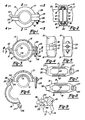
- Fig. 2 illustrates the coupling 10 connecting the adjacent ends of a pair of pipes 11 and 12. These pipes are provided with annular grooves 13 for engaging the coupling.
- the coupling is formed of an upper, arcuate segment 15 and a lower, arcuate segment 16 which are aligned to form the complete circular coupling housing. These segments are U-shaped in cross-section so as to provide a continuous, annular groove 17 within the housing formed by the aligned segments.
- the opposite sides or legs 18 which define the continuous grooves 17 are narrowed at their free edges to form annular engagement edges or keys 19 which fit into the surface grooves 13 which they respectively overlap.
- a rubber-like gasket 20 which may be U-shaped as illustrated in cross-section in Fig. 2, is inserted within the groove 17 for surrounding the pipe junction and for engaging the ends of the pipes.
- a rubber-like gasket 20 which may be U-shaped as illustrated in cross-section in Fig. 2
- This gasket construction is conventional and is described here by way of background.
- each of the segments have radially outwardly extending lugs which are overlapped to form pairs of lugs that are fastened together in order to align and secure the segments to each other.
- the upper segment 15 is provided with an outwardly extending lug 25, which may be formed hollow.
- the opposite, lower segment is provided with a lug 26 which is a mirror image of the lug 25.
- the two lugs are overlapped and are engaged together for fastening.
- each of the lugs are provided with aligned, elongated slot-like, openings 27 (see Figs. 7 and 8), which receive a bolt 28. The bolt is secured in place by a suitable nut 29 for fixing the lugs 25 and 26 together.
- the lower segment 16 has a radially outwardly extending lug 31 formed on its opposite end.
- This lug is extended to provide a curved hook 32 which is substantially an arc of a circle.
- the lug 33 extending radially outwardly from the upper segment is provided with an elongated, narrow, hook receiving opening 34 (see Fig. 7).
- the axle is rounded, at least along the portions engaged by the curved hook 32.
- the hook is of a rectangular cross-section, which is uniform, so as to substantially fill the opening 34.
- the hook is of a sufficient length (see Fig.
- the plumber arranges the upper segment 15, generally horizontally, over the adjacent ends of the pipes, while allowing the lower segment to gravity hang beneath, suspended by the hook and axle.
- the plumber may swing the lower segment upwardly and apply the bolt 28.
- the bolt may be left in place through the lug 25 on the upper segment 15 so that it may be easily slipped into the opening 27 in the lower lug 26 and the nut may be manually applied to hold the lower segment in place.
- the nut can be tightened with a suitable wrench. Consequently, the plumber may use one hand to hold the coupling in place while the other hand is free to take care of the necessary manipulations and preparations to complete the coupling.
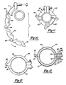
- Figs. 10 and 11 illustrate a modified form of the coupling 40 which is made of a number of arcuate segments arranged end to end to form the circular coupling housing. Three, four or more segments may be utilized depending upon the size of the pipes to be coupled. This construction permits coupling the ends of very large pipes by using enough segments to make the coupling handleable by a plumber.
- Figs. 10 and 11 illustrate the use of a lead segment 41 which is substantially identical to the previously mentioned upper segment 15 with respect to the opposite lugs, except that the lugs span a 90 degree arc.
- a final segment 42 is substantially identical to the lower segment 16, except for spanning a 90 degree arc.
- Intermediate segments 43 are substantially identical to the previously described segments, with the exception that they each have a hook on one end and a hook receiving opening on their opposite end, similar in construction so that previously described. Consequently, the intermediate segments, along with the final segment, may gravity hang or dangle beneath the lead segment which may be held in place upon the pipes manually by one hand. The segments form a chain hanging beneath the lead segment.
- Figs. 12 and 13 show another modified form of coupling 49 formed with an upper segment 50 and a lower segment 51. These segments are substantially the same as the upper segment 15 and lower segment 16. However, the pairs of lugs are somewhat modified. That is, the hook-lug 52 of the lower segment 51 is somewhat more streamlined or narrowed to reduce the amount of metal required. Its hook 53 extends through the opening 54 in the upper lug 55.
- the opposite pair of lugs that is, the upper lug 56 and the lower lug 57, are U-shaped in cross-section.
- the upper lug 56 has a horizontal base 58 and a pair of spaced apart side legs 59 which are notched at their edges to form alignment notches 60.
- a radially opening slot 61 is formed in the base 58 so that the slot opens radially sideways of the coupling as well as upwardly and downwardly.
- the radial slot 61 receives the bolt sideways as well as endwise as will be further described.
- the base 62 of the lower lug has integral, parallel, spaced apart legs 63, each of which has upwardly extending projections or teeth which closely fit into the respective edge notches 60 of the upper lug legs.
- the upper segment 50 is positioned upon the aligned pipe ends with the lower segment gravity hanging beneath it.
- a bolt 65 having a nut 66 loosely held within the opening 67 of the lower lug is used to fasten the two lugs together.
- the plumber may tighten the nut manually until the parts are held together, at which point he can release his grasp of the coupling segments and tighten the nut with a wrench for completing the coupling assembly.
Landscapes
- Engineering & Computer Science (AREA)
- General Engineering & Computer Science (AREA)
- Physics & Mathematics (AREA)
- Fluid Mechanics (AREA)
- Mechanical Engineering (AREA)
- Joints With Sleeves (AREA)
- Mutual Connection Of Rods And Tubes (AREA)
- Supports For Pipes And Cables (AREA)
- Non-Disconnectible Joints And Screw-Threaded Joints (AREA)
Priority Applications (1)
| Application Number | Priority Date | Filing Date | Title |
|---|---|---|---|
| AT90302865T ATE84863T1 (de) | 1989-05-19 | 1990-03-16 | Schwenkbare rohrverbindung. |
Applications Claiming Priority (2)
| Application Number | Priority Date | Filing Date | Title |
|---|---|---|---|
| US354298 | 1989-05-19 | ||
| US07/354,298 US4915418A (en) | 1989-05-19 | 1989-05-19 | Hinged pipe coupling |
Publications (2)
| Publication Number | Publication Date |
|---|---|
| EP0398471A1 true EP0398471A1 (fr) | 1990-11-22 |
| EP0398471B1 EP0398471B1 (fr) | 1993-01-20 |
Family
ID=23392686
Family Applications (1)
| Application Number | Title | Priority Date | Filing Date |
|---|---|---|---|
| EP90302865A Expired - Lifetime EP0398471B1 (fr) | 1989-05-19 | 1990-03-16 | Jonction articulée pour tuyaux |
Country Status (5)
| Country | Link |
|---|---|
| US (1) | US4915418A (fr) |
| EP (1) | EP0398471B1 (fr) |
| AT (1) | ATE84863T1 (fr) |
| CA (1) | CA2010752C (fr) |
| DE (1) | DE69000786T2 (fr) |
Cited By (1)
| Publication number | Priority date | Publication date | Assignee | Title |
|---|---|---|---|---|
| USD938557S1 (en) | 2019-04-19 | 2021-12-14 | Aalberts Integrated Piping Systems Apac Inc. | Coupling |
Families Citing this family (79)
| Publication number | Priority date | Publication date | Assignee | Title |
|---|---|---|---|---|
| US5018768A (en) * | 1990-07-19 | 1991-05-28 | Quikcoup, Incorporated | Pipe coupling hinge |
| US5372392A (en) * | 1993-06-24 | 1994-12-13 | Norgren Co. | Connecting devices |
| CA2127957A1 (fr) | 1993-09-29 | 1995-03-30 | Gerald A. Babuder | Raccord a brides etanches pour tuyauterie |
| US5647612A (en) * | 1994-04-04 | 1997-07-15 | Nippondenso Co., Ltd. | Coupling for pipes |
| US5689862A (en) * | 1996-05-02 | 1997-11-25 | Spm, Inc. | Safety clamp |
| US5947533A (en) * | 1996-08-02 | 1999-09-07 | Fisher; Ronald K. | Gasket assembly with elastomer expansion area |
| US6139069A (en) * | 1998-08-24 | 2000-10-31 | Central Sprinkler Corporation | Universal mechanical coupling with interfitting ends |
| US6056332A (en) * | 1999-03-09 | 2000-05-02 | Foster; Clark | Clamping apparatus |
| KR200262261Y1 (ko) * | 2001-10-16 | 2002-03-18 | 한양프레임주식회사 | 안내판 지지구조 |
| USD482956S1 (en) | 2003-01-22 | 2003-12-02 | Thomas & Betts International, Inc. | Split coupling |
| USD488714S1 (en) | 2003-04-29 | 2004-04-20 | C & S Manufacturing Co. | Sub-grade conduit connector |
| US20050000062A1 (en) * | 2003-07-02 | 2005-01-06 | Peter Lin | Clamping device for glass containers with flanged connections |
| US20050082831A1 (en) * | 2003-10-15 | 2005-04-21 | Borland Robin N. | Conduit coupling |
| WO2005094292A2 (fr) * | 2004-03-26 | 2005-10-13 | Victaulic Company Of America | Raccord de conduit comprenant des cales cuneiformes |
| US8267432B2 (en) * | 2004-03-26 | 2012-09-18 | Victaulic Company | Coupling having angularly oriented key surfaces |
| US7712796B2 (en) * | 2004-05-14 | 2010-05-11 | Victaulic Company | Deformable mechanical pipe coupling |
| US7086131B2 (en) * | 2004-05-14 | 2006-08-08 | Victaulic Company | Deformable mechanical pipe coupling |
| US7540071B2 (en) * | 2005-03-23 | 2009-06-02 | Franklin Fastener Company | Interlocked two-part clamp |
| US7726703B2 (en) * | 2006-06-07 | 2010-06-01 | Victaulic Company | Deformable pipe coupling having multiple radii of curvature |
| US8870233B2 (en) | 2007-07-03 | 2014-10-28 | S.P.M. Flow Control, Inc. | Swivel joint with uniform ball bearing requirements |
| CA2705351C (fr) * | 2007-10-03 | 2014-01-21 | Anvil International, Lp | Joints de raccords et procedes associes |
| US20090243289A1 (en) * | 2008-02-12 | 2009-10-01 | Victaulic Company | Couplings Having Stiffening Ribs and Keys with Oppositely Disposed Camming Surfaces |
| US8282136B2 (en) | 2008-06-30 | 2012-10-09 | Mueller International, Llc | Slip on groove coupling with multiple sealing gasket |
| SG175263A1 (en) | 2009-04-20 | 2011-11-28 | Weir Spm Inc | Flowline flapper valve |
| MX2011012944A (es) | 2009-06-03 | 2012-06-12 | Spm Flow Control Inc | Indicador de valvula de tapon. |
| US11274777B2 (en) | 2009-06-12 | 2022-03-15 | Romac Industries, Inc. | Pipe coupling |
| US8448993B2 (en) * | 2009-06-12 | 2013-05-28 | Romac Industries, Inc. | Pipe coupling |
| MX2012004918A (es) * | 2009-10-27 | 2012-06-19 | Tyco Fire Products Lp | Sistema y metodos para acoplamientos articulados. |
| ES2555497T3 (es) | 2009-10-27 | 2016-01-04 | Tyco Fire Products Lp | Sistemas y métodos para acoplamientos de cañerías |
| RU2418227C1 (ru) | 2009-11-20 | 2011-05-10 | Общество с ограниченной ответственностью "Аквафор" | Быстросборное фланцевое соединение |
| KR20110060832A (ko) * | 2009-11-30 | 2011-06-08 | 이하라 사이언스 가부시키가이샤 | 결합링 |
| US20110169384A1 (en) * | 2010-01-13 | 2011-07-14 | Brass Smith, LLC (Subsidiary of Kevry Corp.) | Food shield |
| US8403430B2 (en) | 2011-02-07 | 2013-03-26 | Brass Smith, Llc | Adjustable food shield |
| US9523449B2 (en) | 2011-03-22 | 2016-12-20 | Airvac, Inc. | Pipe coupling |
| JP2014523999A (ja) * | 2011-06-15 | 2014-09-18 | アミアド ウォーター システムズ リミテッド | 管状部材の結合器 |
| USD696751S1 (en) | 2011-10-27 | 2013-12-31 | Mueller International, Llc | Slip-on gasket |
| USD680630S1 (en) | 2011-11-21 | 2013-04-23 | Mueller International, Llc | Slip-on coupling assembly |
| US20130125373A1 (en) * | 2011-11-21 | 2013-05-23 | Philip W. Bancroft | Coupling with projections having angularly oriented surface portions |
| USD680629S1 (en) | 2011-11-21 | 2013-04-23 | Mueller International, Llc | Slip-on coupling segment |
| US9039046B2 (en) | 2012-01-20 | 2015-05-26 | Mueller International, Llc | Coupling with tongue and groove |
| US9194516B2 (en) | 2012-01-20 | 2015-11-24 | Mueller International, Llc | Slip-on coupling |
| US9534715B2 (en) | 2012-01-20 | 2017-01-03 | Mueller International, Llc | Coupling gasket with multiple sealing surfaces |
| US9500307B2 (en) | 2012-01-20 | 2016-11-22 | Mueller International, Llc | Slip-on coupling gasket |
| US8894100B2 (en) | 2012-03-16 | 2014-11-25 | Romac Industries, Inc. | Fitting with draw mechanism |
| US10527265B2 (en) * | 2012-04-13 | 2020-01-07 | Ideal Industries Lighting Llc | Mounting assembly for light fixture |
| DE102012009256B4 (de) * | 2012-05-02 | 2015-08-06 | Norma Germany Gmbh | Profilschelle |
| US9291290B2 (en) | 2012-05-21 | 2016-03-22 | Havaco Technologies | Foldable HVAC conduit and duct collar |
| US9103448B2 (en) | 2012-08-16 | 2015-08-11 | S.P.M. Flow Control, Inc. | Plug valve having preloaded seal segments |
| US9273543B2 (en) | 2012-08-17 | 2016-03-01 | S.P.M. Flow Control, Inc. | Automated relief valve control system and method |
| US9322243B2 (en) | 2012-08-17 | 2016-04-26 | S.P.M. Flow Control, Inc. | Automated relief valve control system and method |
| US9168585B2 (en) | 2012-11-02 | 2015-10-27 | Mueller International, Llc | Coupling with extending parting line |
| USD707332S1 (en) | 2013-03-15 | 2014-06-17 | S.P.M. Flow Control, Inc. | Seal assembly |
| USD707797S1 (en) | 2013-03-15 | 2014-06-24 | S.P.M. Flow Control, Inc. | Seal segment |
| US10058198B2 (en) | 2013-06-18 | 2018-08-28 | Brass Smith Innovations, Llc | Food service equipment and systems |
| CA2916699A1 (fr) | 2013-07-01 | 2015-01-08 | S.P.M. Flow Control, Inc. | Ensemble collecteur |
| NL2011194C2 (en) * | 2013-07-18 | 2015-01-21 | Walraven Holding Bv J Van | Pipe clip with locking feature. |
| DE102014100248A1 (de) * | 2014-01-10 | 2015-07-16 | Illinois Tool Works Inc. | Befüllvorrichtung für einen Fahrzeugtank |
| USD735025S1 (en) * | 2014-01-28 | 2015-07-28 | Behringer Corporation | Hygienic clamp |
| USD749835S1 (en) * | 2014-08-21 | 2016-02-23 | Nordson Corporation | Reusable clamp with latch release arm |
| US9782022B2 (en) | 2015-02-12 | 2017-10-10 | Brass Smith Llc | Adjustable food shield with detents |
| USD756759S1 (en) | 2015-02-18 | 2016-05-24 | Brass Smith Llc | Support column for a food shield |
| WO2016205208A1 (fr) | 2015-06-15 | 2016-12-22 | S.P.M. Flow Control, Inc. | Écrou à ailettes à rayon à fond de filet ayant une épaisseur de paroi augmentée |
| US10677365B2 (en) | 2015-09-04 | 2020-06-09 | S.P.M. Flow Control, Inc. | Pressure relief valve assembly and methods |
| US11378208B2 (en) | 2016-12-14 | 2022-07-05 | ASC Engineered Solutions, LLC | Pipe couplings |
| TWI726211B (zh) * | 2017-05-30 | 2021-05-01 | 美商泰科防火產品有限合夥公司 | 用於插入管端的預裝配式管聯接器及用預裝配式聯接器將一對軸向佈置的管端連結之方法 |
| EP3631270B1 (fr) | 2017-05-30 | 2023-09-20 | Tyco Fire Products LP | Raccord de tuyau pré-assemblé doté d'une limite d'insertion pour la réception axiale d'extrémités de tuyau |
| US9890884B1 (en) * | 2017-07-30 | 2018-02-13 | Eliezer Krausz Industrial Development Ltd. | Clamping ring with improved connecting structure |
| US11448346B2 (en) * | 2018-09-28 | 2022-09-20 | ASC Engineered Solutions, LLC | Pipe coupling |
| CN109442108B (zh) * | 2018-12-14 | 2024-05-03 | 山东莱德机械有限公司 | 一种快连卡箍 |
| US10711929B1 (en) * | 2019-06-29 | 2020-07-14 | Shanghai Vision Mechanical Joint Co., Ltd. | Pipe element coupler and coupling method thereof |
| US11577038B2 (en) | 2019-07-11 | 2023-02-14 | Will Stuckey | Endotracheal tube to bag valve device connecting assembly |
| US11339910B1 (en) * | 2019-08-16 | 2022-05-24 | Brad Brown | Line pipe field joint shroud |
| CN113757461A (zh) * | 2021-02-07 | 2021-12-07 | 上海威逊机械连接件有限公司 | 快装接头 |
| US11808293B2 (en) * | 2021-02-25 | 2023-11-07 | Bae Systems Information And Electronic Systems Integration Inc. | V-band clamp |
| US20220341527A1 (en) * | 2021-04-27 | 2022-10-27 | Victaulic Company | Mechanical Outlet |
| US11549633B1 (en) * | 2021-09-01 | 2023-01-10 | Saudi Arabian Oil Company | Protecting a portion of a pipeline from an impact |
| CN113700954A (zh) * | 2021-09-08 | 2021-11-26 | 山东鲁源消防科技有限公司 | 一种卡扣式快卡 |
| EP4449001A1 (fr) | 2021-12-17 | 2024-10-23 | Lubrizol Advanced Materials, Inc. | Appareil à tuyau, dispositifs de couplage et procédés |
| USD1036249S1 (en) * | 2022-03-01 | 2024-07-23 | Bizlink Industry Germany Gmbh | Fastening ring |
Citations (4)
| Publication number | Priority date | Publication date | Assignee | Title |
|---|---|---|---|---|
| CH390637A (fr) * | 1962-12-07 | 1965-04-15 | Soc D Const D App Mecaniques I | Dispositif de raccordement, notamment pour pièces tubulaires |
| US3464722A (en) * | 1968-04-19 | 1969-09-02 | Sam Larkin | Pipe coupling having segmented clamping means |
| US4561678A (en) * | 1983-05-04 | 1985-12-31 | Victaulic Company Of America | Pipe coupling |
| EP0265141A1 (fr) * | 1986-10-21 | 1988-04-27 | Victaulic Company Of America | Raccords de tuyaux pivotants et segmentaires |
Family Cites Families (8)
| Publication number | Priority date | Publication date | Assignee | Title |
|---|---|---|---|---|
| US735989A (en) * | 1903-02-16 | 1903-08-11 | Frank T Lippincott | Hose-clamp. |
| US875019A (en) * | 1907-07-11 | 1907-12-31 | Henry A Wahlert | Hose-clamp. |
| US1093868A (en) * | 1912-03-11 | 1914-04-21 | Henry W Jacobs | Means for forming couplings or joints. |
| US1187430A (en) * | 1915-01-16 | 1916-06-13 | Leonard C Grove | Hose-clamp. |
| US2449795A (en) * | 1944-02-14 | 1948-09-21 | Well Equipment Mfg Corp | Pipe coupling |
| FR1196266A (fr) * | 1958-05-21 | 1959-11-23 | Collier d'assemblage de tuyaux | |
| US3014259A (en) * | 1958-10-21 | 1961-12-26 | Joseph Louis | Two-piece clamp |
| US4408788A (en) * | 1981-09-23 | 1983-10-11 | Grinnell Fire Protection Systems Company, Inc. | Hingeable split pipe collar |
-
1989
- 1989-05-19 US US07/354,298 patent/US4915418A/en not_active Expired - Lifetime
-
1990
- 1990-02-22 CA CA002010752A patent/CA2010752C/fr not_active Expired - Fee Related
- 1990-03-16 AT AT90302865T patent/ATE84863T1/de not_active IP Right Cessation
- 1990-03-16 DE DE9090302865T patent/DE69000786T2/de not_active Expired - Fee Related
- 1990-03-16 EP EP90302865A patent/EP0398471B1/fr not_active Expired - Lifetime
Patent Citations (4)
| Publication number | Priority date | Publication date | Assignee | Title |
|---|---|---|---|---|
| CH390637A (fr) * | 1962-12-07 | 1965-04-15 | Soc D Const D App Mecaniques I | Dispositif de raccordement, notamment pour pièces tubulaires |
| US3464722A (en) * | 1968-04-19 | 1969-09-02 | Sam Larkin | Pipe coupling having segmented clamping means |
| US4561678A (en) * | 1983-05-04 | 1985-12-31 | Victaulic Company Of America | Pipe coupling |
| EP0265141A1 (fr) * | 1986-10-21 | 1988-04-27 | Victaulic Company Of America | Raccords de tuyaux pivotants et segmentaires |
Cited By (3)
| Publication number | Priority date | Publication date | Assignee | Title |
|---|---|---|---|---|
| USD938557S1 (en) | 2019-04-19 | 2021-12-14 | Aalberts Integrated Piping Systems Apac Inc. | Coupling |
| USD939672S1 (en) | 2019-04-19 | 2021-12-28 | Aalberts Integrated Piping Systems Apac Inc. | Coupling |
| US11421804B2 (en) | 2019-04-19 | 2022-08-23 | Aalberts integrated piping systems APAC, Inc. | Quick installation coupling |
Also Published As
| Publication number | Publication date |
|---|---|
| DE69000786T2 (de) | 1993-07-22 |
| US4915418A (en) | 1990-04-10 |
| ATE84863T1 (de) | 1993-02-15 |
| EP0398471B1 (fr) | 1993-01-20 |
| CA2010752C (fr) | 2000-05-09 |
| CA2010752A1 (fr) | 1990-11-19 |
| DE69000786D1 (de) | 1993-03-04 |
Similar Documents
| Publication | Publication Date | Title |
|---|---|---|
| US4915418A (en) | Hinged pipe coupling | |
| US4561678A (en) | Pipe coupling | |
| US5380052A (en) | Releasable handle-type fastener for pipe couplings | |
| TWI317001B (en) | Method for joining pipe elements in end to end relation | |
| JP3300385B2 (ja) | パイプカップリングヒンジ | |
| TWI336381B (en) | Coupling with concave bearing surface | |
| CA1300660C (fr) | Presse-garniture segmente servant a maintenir des joints de tuyaux | |
| US5366263A (en) | Releasable fastener for pipe couplings | |
| US4722468A (en) | Boiler pipe tool for heliarc welding with tongue and groove interlock | |
| US20090206598A1 (en) | Method of Securing Pipe Elements End to End | |
| EP0412642A1 (fr) | Accouplement rigide ou flexible pour tuyaux | |
| US3281929A (en) | Apparatus for assembling bell-andspigot piping | |
| CA2150808A1 (fr) | Outil de presse | |
| JPH08105580A (ja) | 管継手ロック装置 | |
| US5000487A (en) | Frangible V-band coupling | |
| JP2022502610A (ja) | 向上した締結力調整システムを備えるパイプカップリング | |
| JP2003028358A (ja) | プロフィールクランプ及びプロフィールクランプを有するスリーブ接合具 | |
| CA2121549A1 (fr) | Appareil pour le raccordement et la suspente d'elements tubulaires | |
| EP0310177B1 (fr) | Connexion détachable | |
| US5628178A (en) | Sprocket chain master link | |
| RU55924U1 (ru) | Устройство для перекрытия трубопровода | |
| JPS5933479B2 (ja) | 配管接合用アウタ−クランプ | |
| RU204648U1 (ru) | Устройство для центрирования торцов труб при сварке | |
| JPS62177391A (ja) | 管用密封継手 | |
| SU1173122A1 (ru) | Быстроразъемный хомут |
Legal Events
| Date | Code | Title | Description |
|---|---|---|---|
| PUAI | Public reference made under article 153(3) epc to a published international application that has entered the european phase |
Free format text: ORIGINAL CODE: 0009012 |
|
| AK | Designated contracting states |
Kind code of ref document: A1 Designated state(s): AT BE CH DE DK ES FR GB GR IT LI LU NL SE |
|
| 17P | Request for examination filed |
Effective date: 19910307 |
|
| 17Q | First examination report despatched |
Effective date: 19910828 |
|
| GRAA | (expected) grant |
Free format text: ORIGINAL CODE: 0009210 |
|
| STAA | Information on the status of an ep patent application or granted ep patent |
Free format text: STATUS: THE PATENT HAS BEEN GRANTED |
|
| AK | Designated contracting states |
Kind code of ref document: B1 Designated state(s): AT BE CH DE DK ES FR GB GR IT LI LU NL SE |
|
| PG25 | Lapsed in a contracting state [announced via postgrant information from national office to epo] |
Ref country code: IT Free format text: LAPSE BECAUSE OF FAILURE TO SUBMIT A TRANSLATION OF THE DESCRIPTION OR TO PAY THE FEE WITHIN THE PRE;WARNING: LAPSES OF ITALIAN PATENTS WITH EFFECTIVE DATE BEFORE 2007 MAY HAVE OCCURRED AT ANY TIME BEFORE 2007. THE CORRECT EFFECTIVE DATE MAY BE DIFFERENT FROM THE ONE RECORDED.SCRIBED TIME-LIMIT Effective date: 19930120 Ref country code: GR Free format text: LAPSE BECAUSE OF FAILURE TO SUBMIT A TRANSLATION OF THE DESCRIPTION OR TO PAY THE FEE WITHIN THE PRESCRIBED TIME-LIMIT Effective date: 19930120 Ref country code: DK Effective date: 19930120 Ref country code: FR Effective date: 19930120 Ref country code: LI Effective date: 19930120 Ref country code: CH Effective date: 19930120 Ref country code: ES Free format text: THE PATENT HAS BEEN ANNULLED BY A DECISION OF A NATIONAL AUTHORITY Effective date: 19930120 Ref country code: AT Effective date: 19930120 Ref country code: SE Effective date: 19930120 Ref country code: NL Effective date: 19930120 |
|
| REF | Corresponds to: |
Ref document number: 84863 Country of ref document: AT Date of ref document: 19930215 Kind code of ref document: T |
|
| REF | Corresponds to: |
Ref document number: 69000786 Country of ref document: DE Date of ref document: 19930304 |
|
| PG25 | Lapsed in a contracting state [announced via postgrant information from national office to epo] |
Ref country code: LU Free format text: LAPSE BECAUSE OF NON-PAYMENT OF DUE FEES Effective date: 19930331 |
|
| REG | Reference to a national code |
Ref country code: CH Ref legal event code: PL |
|
| EN | Fr: translation not filed | ||
| NLV1 | Nl: lapsed or annulled due to failure to fulfill the requirements of art. 29p and 29m of the patents act | ||
| PLBE | No opposition filed within time limit |
Free format text: ORIGINAL CODE: 0009261 |
|
| 26N | No opposition filed | ||
| PLBG | Opposition deemed not to have been filed |
Free format text: ORIGINAL CODE: 0009274 |
|
| 26D | Opposition deemed not to have been filed | ||
| PLAA | Information modified related to event that no opposition was filed |
Free format text: ORIGINAL CODE: 0009299DELT |
|
| REG | Reference to a national code |
Ref country code: GB Ref legal event code: IF02 |
|
| PGFP | Annual fee paid to national office [announced via postgrant information from national office to epo] |
Ref country code: DE Payment date: 20060309 Year of fee payment: 17 |
|
| PGFP | Annual fee paid to national office [announced via postgrant information from national office to epo] |
Ref country code: GB Payment date: 20060315 Year of fee payment: 17 |
|
| PGFP | Annual fee paid to national office [announced via postgrant information from national office to epo] |
Ref country code: BE Payment date: 20060509 Year of fee payment: 17 |
|
| GBPC | Gb: european patent ceased through non-payment of renewal fee |
Effective date: 20070316 |
|
| BERE | Be: lapsed |
Owner name: *QUIKCOUP INC. Effective date: 20070331 |
|
| PG25 | Lapsed in a contracting state [announced via postgrant information from national office to epo] |
Ref country code: BE Free format text: LAPSE BECAUSE OF NON-PAYMENT OF DUE FEES Effective date: 20070331 |
|
| PG25 | Lapsed in a contracting state [announced via postgrant information from national office to epo] |
Ref country code: DE Free format text: LAPSE BECAUSE OF NON-PAYMENT OF DUE FEES Effective date: 20071002 |
|
| PG25 | Lapsed in a contracting state [announced via postgrant information from national office to epo] |
Ref country code: GB Free format text: LAPSE BECAUSE OF NON-PAYMENT OF DUE FEES Effective date: 20070316 |