EP0398598B1 - Horizontal-Ablenkschaltungen - Google Patents
Horizontal-Ablenkschaltungen Download PDFInfo
- Publication number
- EP0398598B1 EP0398598B1 EP90305102A EP90305102A EP0398598B1 EP 0398598 B1 EP0398598 B1 EP 0398598B1 EP 90305102 A EP90305102 A EP 90305102A EP 90305102 A EP90305102 A EP 90305102A EP 0398598 B1 EP0398598 B1 EP 0398598B1
- Authority
- EP
- European Patent Office
- Prior art keywords
- signal
- horizontal
- deflection
- circuit
- output
- Prior art date
- Legal status (The legal status is an assumption and is not a legal conclusion. Google has not performed a legal analysis and makes no representation as to the accuracy of the status listed.)
- Expired - Lifetime
Links
Images

Classifications
-
- H—ELECTRICITY
- H04—ELECTRIC COMMUNICATION TECHNIQUE
- H04N—PICTORIAL COMMUNICATION, e.g. TELEVISION
- H04N3/00—Scanning details of television systems; Combination thereof with generation of supply voltages
- H04N3/10—Scanning details of television systems; Combination thereof with generation of supply voltages by means not exclusively optical-mechanical
- H04N3/16—Scanning details of television systems; Combination thereof with generation of supply voltages by means not exclusively optical-mechanical by deflecting electron beam in cathode-ray tube, e.g. scanning corrections
- H04N3/27—Circuits special to multi-standard receivers
Definitions
- This invention relates to horizontal deflection circuits, and more particularly to horizontal deflection circuits for use with multiple-scanning type television receivers that can receive video signals having different horizontal frequencies.
- FIG. 1 An example of a proposed horizontal deflection circuit for use in a multiple-scanning type television receiver is shown in Figure 1.
- a horizontal synchronizing signal is applied to an input terminal 1, and then fed to a frequency-to-voltage converter 2, where it is converted to a voltage signal whose level is changed in proportion to the frequency of the horizontal synchronizing signal.
- the voltage signal from the converter 2 is supplied to one input of a multiplier 3.
- a second input terminal 4 has supplied thereto a deflection control signal that is used to vary the width of deflection of the beam in the horizontal direction.
- the deflection control signal applied to the input terminal 4 is supplied to the other input terminal of the multiplier 3, so that the voltage signal corresponding to the frequency of the horizontal synchronizing signal is changed in response to the deflection width indicated by the deflection control signal.
- the product signal from the multiplier 3 is supplied to a switching regulator 5 as a control signal, and the switching regulator 5 produces a DC output signal in response to the multiplied signal.
- This DC output signal is supplied to a horizontal output circuit 6 as a power supply source signal, and the horizontal synchronizing signal at the input terminal 1 is also supplied to the horizontal output circuit 6, whereby a horizontal deflection output signal having a cycle based on the horizontal synchronizing signal is developed at an output terminal 6a, which is connected to the deflection coil (not shown) of the television receiver.
- the horizontal deflection width can be controlled to fall substantially in a predetermined range, regardless of changes in the line frequency of the video input signal.
- the horizontal deflection circuit may be constructed as shown in Figure 2, in which like parts corresponding to those of Figure 1 have the same reference numerals and will not be described in detail.
- the horizontal synchronizing signal applied to the horizontal synchronizing signal input terminal 1 is again supplied directly to the horizontal output circuit 6, and the output signal from the horizontal output circuit 6 is supplied to a deflection width detecting circuit 7.
- the deflection width detecting circuit 7 detects a horizontal deflection width from the output signal of the horizontal output circuit 6, and produces an output signal that is integrated by an integrating circuit 8, and is then fed to one input of a comparator 9.
- An electronic control signal that is proportional to the deflection width is applied to a deflection control signal input terminal connected to the other input of comparator 9.
- the comparator 9 compares the deflection width indicated by the control signal with a real deflection width indicated by the detected signal to generate a compared result, that is, a difference signal.
- This difference signal is supplied to the switching regulator 5 as a control signal, and a DC signal from the switching regulator 5 is supplied to the horizontal output circuit 6 as a power source voltage.
- the deflection width detecting circuit 7 operates so that a horizontal deflection pulse signal derived from the horizontal output circuit 6 is peak-rectified, thereby detecting the deflection width from a rectified value.
- a peak-rectified value P1 of the horizontal deflection pulse signal will change in a predetermined range near the peak value of the pulse signal, as shown by a solid line in Figure 3.
- the interval between the horizontal deflection pulse signals is widened by a factor of two, whereby the width in which a peak-rectified value P2 is changed is widened to twice that of the peak-rectified value P1.
- the mean value level a2 will be lower than the mean value level a1.
- the horizontal frequency of video signals has become higher and higher.
- the horizontal frequency may be as high as several times the horizontal frequency of the ordinary broadcasting standard (15.75 kHz). If a video signal with such a high horizontal frequency is supplied to the detecting circuit, there is then the substantial possibility that an error will occur in detecting the deflection width.
- the horizontal deflection width can be controlled to fall substantially in a predetermined range. More particularly, the deflection width to be controlled and the real deflection width are compared by the comparator 9, and the switching regulator 5 is controlled so as to reduce the resultant difference, whereby the horizontal deflection width can be prevented from fluctuating with changes in horizontal frequency.
- the horizontal deflection circuit shown in Figure 1 has the unavoidable disadvantage that the horizontal deflection width fluctuates very slightly in accordance with an increase in horizontal frequency fH of the incoming video signal.
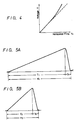
- the horizontal frequency fH and the output voltage V of the switching regulator 5 are directly proportional to each other, as shown by a dashed line in Figure 4, in practice the output voltage V increases at a higher rate in accordance with increases of the horizontal frequency fH, as shown by a solid line in Figure 4, resulting in the horizontal deflection width fluctuating by about 10 to 20%.
- the reason that the horizontal deflection width fluctuates is that even although the horizontal frequency changes, the beam blanking period, or retrace period, does not change. This will be described in more detail with reference to Figures 5A and 5B.
- the change in the horizontal frequency and the change of the video scanning period are not directly proportional to each other, so that in the horizontal deflection circuit of Figure 1 an error occurs in the deflection width in accordance with the increase of the horizontal frequency, whereby a fluctuation in the deflection width occurs.
- a horizontal deflection circuit for a multiple-scanning type television receiver that displays input video signals having different respective horizontal frequencies, the circuit comprising: a horizontal output circuit responsive to an input horizontal synchronizing signal for producing a horizontal deflection output signal; characterized by a detecting circuit responsive to said horizontal deflection output signal for detecting a deflection width of an input video signal and producing a detected output signal; and a comparator for comparing said detected output signal with a picture size signal proportional to a picture size of the input video signal in the horizontal direction and producing a compared output signal; a voltage signal generator responsive to said input horizontal synchronizing signal for generating a voltage signal proportional to the horizontal frequency of the input video signal; an adder for adding the compared output signal from the comparator (20) and the picture size signal; and a multiplier for multiplying an output signal of said adder and said voltage signal, and producing an output signal for controlling said horizontal output circuit of the television receiver.
- the horizontal output circuit of the television receiver is controlled on the basis of the output signal of the multiplying circuit.
- a horizontal deflection width detecting circuit in which a horizontal deflection width of a video signal supplied to a multiple-scanning type television receiver capable of receiving a video signal of a plurality of horizontal frequencies is detecting by peak-rectifying a horizontal deflection pulse.
- a discharging current source proportional to the horizontal frequency of the input video signal is connected to a peak-rectifying circuit, so that a deflection width can be satisfactorily detected without error.
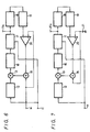
- FIG. 6 an embodiment of horizontal deflection circuit according to the present invention is shown, in which the horizontal deflection circuit is applied to a so-called multiple-scanning type television receiver.
- a horizontal synchronizing signal of an input video signal of the kind that is supplied to the above-described multiple-scanning type television receiver (not shown) is fed to an input terminal 11 and supplied to a frequency-to-voltage converter 12, in which it is converted to a voltage signal whose voltage level changes in proportion to the frequency of the horizontal synchronising signal.
- the voltage signal output from the converter 12 is supplied to one input of a multiplier 13.
- Another input terminal 14 receives a deflection control signal having a voltage level proportional to a deflection width as determined by the size of the picture to be displayed on the television receiver screen.
- the deflection control signal applied to the input terminal 14 is fed to one input of an adder 15.
- the deflection control signal might be a voltage signal that is 1 Volt when the picture is a standard size and which becomes 0.5 Volt when the picture is half the standard size.
- the adder 15 also receives at another input a difference signal from a comparator 20, and the adder 15 adds the deflection control signal and the difference signal.
- the sum signal output from the adder 15 is supplied to the other input of the multiplier 13, so that in the multiplier 13 the voltage signal corresponding to the frequency of the horizontal synchronizing signal is changed in response to the sum signal by the multiplication operation, and the product signal is supplied as a control signal to a switching regulator 16.
- the switching regulator 16 generates a DC output signal in response to the multiplied signal that is supplied to a horizontal output circuit 17 as a power supply source signal.
- the horizontal synchronizing signal applied to the input terminal 11 is also supplied to the horizontal output circuit 17, whereby a horizontal deflection output signal based on the horizontal synchronizing signals is fed to an output terminal 17a that is connected to the horizontal deflection coil (not shown).
- the output signal from the horizontal output circuit 17 is also supplied to a deflection width detecting circuit 18, wherein a horizontal deflection width of the output signal of the horizontal output circuit 17 is detected by the deflection width detecting circuit 18.
- the detected signal is supplied to an integrating circuit 19, in which it is integrated and is fed as one input to the comparator 20.
- the deflection control signal that is proportional to the deflection width and that is applied to the deflection control signal input terminal 14 is the other signal supplied to the comparator 20.
- the comparator 20 compares the deflection width indicated by the control signal with a real deflection width to generate a compared result, that is, a difference signal.
- the difference signal from the comparator 20 is supplied to the other input of the adder 15.
- the voltage signal from the converter 12 is a signal based on the frequency of the horizontal synchronizing signal applied to the input terminal 11.
- the signals added by the adder 15 are the deflection control signal applied to the input terminal 14 and the difference signal from the comparator 20.
- the comparator 20 compares the deflection control signal, which is applied to the input terminal 14 and whose level is determined by the size of the picture, and the detected signal indicative of the real deflection state in the horizontal output circuit 17 and which is detected by the deflection width detecting circuit 18. More specifically, the difference between the deflection width to be controlled and the real deflection width is represented by the difference signal from the comparator 20.
- the power supply source signal supplied to the horizontal output circuit 17 is controlled as described above, whereby the power supply source signal proportional to the horizontal frequency of the incoming video signal is controlled by the converter 12, and the power supply source signal based on the difference between the real deflection width and the deflection width corresponding to the size of picture is controlled by the comparator 20.
- control proportional to the horizontal frequency of the input video signal by the converter 12 results in a maximum error of about 20% due to the horizontal frequency fH, as shown in Figure 4, the converter 12 has a high response characteristic relative to fluctuations in the horizontal frequency, so that the output source voltage signal of the switching regulator 16 can be changed in a ganged relation to fluctuations of the horizontal frequency, thereby resulting in a very small error.
- This error is detected as the difference signal by the comparator 20 and the deflection control signal is corrected on the basis of this difference signal, whereby the voltage signal after being multiplied by the multiplier 13 is a voltage signal whose error is corrected. Therefore, the switching regulator 16 can be controlled satisfactorily without error, and a good power supply source voltage signal without error, which can cope with fluctuations of the horizontal frequency, is supplied to the horizontal output circuit 17, thus making it possible to perform satisfactory horizontal deflection following fluctuations of the horizontal frequency, so that the size of the picture is not changed at all.
- the error at that time is about 20% of the fluctuation at maximum, as described above, so that the comparator 20 can be prevented from detecting a large difference of the deflection width. Accordingly, even when the response characteristic is made low by the integrating circuit 19, the amount to be corrected is small. Thus, when the horizontal frequency fH changes rapidly, the horizontal output circuit 17 can be prevented from being overdriven and damaged.
- the horizontal deflection circuit of the first embodiment is modified so that the size of the picture is fixed.
- the deflection control signal is formed of a signal of constant potential from a reference voltage source 21 and supplied to one input terminal of the adder 15 and to an input of the comparator 20.
- the remainder of this embodiment is the same as that of Figure 6.
- the comparator 20 compares the real deflection width and a constant deflection width, so that a deflection width being controlled always falls within a predetermined range.
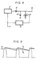
- Figure 8 shows a basic horizontal deflection width detecting circuit.
- the horizontal synchronizing signal supplied to the input terminal 11 is also supplied to the horizontal output circuit 17, and the horizontal output circuit 17 produces a horizontal deflection pulse signal whose phase is matched with that of the horizontal synchronizing signal.
- This horizontal deflection pulse signal is applied to one side of the horizontal deflection coil (not shown), that causes an electron beam to be deflected in the horizontal direction. Simultaneously, this horizontal deflection pulse signal is supplied to a horizontal deflection detecting circuit.
- the horizontal deflection pulse signal from the horizontal output circuit 17 is supplied to the anode of a diode 22 whose cathode is connected to one electrode of a charging capacitor 23.
- the other electrode of the capacitor 23 is earthed.
- the cathode of the diode 22 is also connected to a current source 24, and the signal developed at the cathode of the diode 22 is fed to a deflection width detecting signal output terminal 25.
- the deflection width is based on the voltage value of the signal developed at the output terminal 25.
- the current value of the current source 24 is controlled by the frequency-to-voltage converter 12 as shown by the connection thereto.
- the converter 12 receives the horizontal synchronizing signal fed in at the horizontal synchronizing signal input terminal 11 and produces an output voltage on the basis of the frequency of that horizontal synchronizing signal.
- the current flow due to the current source 24 is controlled by the output voltage signal from the converter 12, so in effect the current flow caused by the current source 24 is controlled in response to the frequency of the horizontal synchronizing signal.
- the horizontal deflection pulse signal from the horizontal output circuit 17 is a pulse signal corresponding to the interval of the horizontal synchronizing signals, as represented by the dashed line in Figure 9.
- a peak value of this pulse signal is peak-rectified by the diode 22 and the capacitor 23. More specifically, this pulse signal charges the capacitor 23, and the current flowing through the current source 24 becomes the discharge current for the capacitor 23.
- the voltage value of the peak-rectified signal developed at the output terminal 25 is determined by the amount of the discharging current.
- the peak value P1 of the horizontal deflection pulse signal determined as described above is represented by the solid line in Figure 9.
- the mean voltage of the output signal at the output terminal can be prevented from changing due to changes in the horizontal frequency. Consequently, errors can be prevented from being produced in the deflection width detection based on the output voltage developed at the output terminal 25.
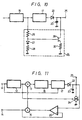
- Figure 10 is a schematic circuit diagram of another embodiment of the present invention, forming a horizontal deflection circuit based on the principle of Figure 8.
- a horizontal deflection pulse signal from the horizontal output circuit 17 is supplied through the diode 22 to the capacitor 23, whose other electrode is earthed.
- the output terminal 25 Connected to the junction of the diode 22 and the capacitor 23 is the output terminal 25, at which a deflection width detecting signal is developed.
- the other end of the resistor 26 is earthed via a series circuit made up of a diode 27 and a resistor 28.
- the base electrode of an NPN transistor 29 is connected.
- the collector electrode of the transistor 29 is connected to the capacitor 23, and the emitter electrode thereof is earthed via a resistor 30 that serves as a discharging resistor.
- a voltage signal proportional to the horizontal frequency is developed at the junction between the resistor 26 and the diode 27 in the current control circuit 24.
- This voltage signal is supplied to the base of the transistor 29, whereby the amount of current flowing through the resistor 30 from the collector-emitter circuit of the transistor 29 is controlled by the voltage signal. Therefore, the discharge of the capacitor 23 is controlled in proportion to the horizontal frequency so that, as long as the horizontal deflection width is constant, as shown in Figure 9, the mean voltage value of the deflection detecting signal developed at the output terminal 25 becomes constant, thereby preventing an error from occurring in the detecting signal.
- the control signal for the current source is not limited to the output signal of the switching regulator 16, as shown in the embodiment of Figure 10, and may be another signal whose voltage level is changed in proportion to the horizontal frequency.
- the amount of the discharging current may be controlled by the output signal of the frequency-to-voltage converter that controls the switching regulator. This will be described more fully with reference to Figure 11.
- the horizontal synchronizing signal applied to the input terminal 11 is supplied to the frequency-to-voltage converter 12, in which it is converted to the voltage signal whose voltage level changes in proportion to the frequency of the horizontal synchronizing signal.
- the voltage signal from the converter 12 is supplied to one input terminal of the multiplier 13.
- the input terminal 14 receives the deflection control signal having a voltage proportional to the deflection width, which is based on the size of the picture to be displayed.
- the deflection control signal applied to the input terminal 14 is supplied to one input terminal of the adder 15.
- the deflection control signal may be a voltage signal that is 1 Volt when the size of the picture is standard and which becomes 0.5 Volt when the size of the picture is half the standard size.
- the adder 15 also receives the difference signal output from the comparator 20, which will be described below.
- the difference signal is added to the deflection control signal, and the summed signal from the adder 15 is supplied to the other input terminal of the multiplier 13.
- the voltage signal corresponding to the frequency of the horizontal synchronizing signal is changed in response to the summed signal by multiplication, and the product signal is supplied to the switching regulator 16 as a control signal.
- the switching regulator 16 generates a DC output signal in response to the product signal from the multiplier 13, and this DC output signal from the switching regulator 16 is supplied to the horizontal output circuit 17 as the power supply source signal.
- the horizontal synchronizing signal applied to the input terminal 11 is supplied to the horizontal output circuit 17, from which there is derived the horizontal deflection pulse signal having a period based on this horizontal synchronizing signal.
- the output signal of the horizontal output circuit 17 is supplied through the diode 22 to the capacitor 23 and to the discharging current source 24.
- the value of current flowing through the current source 24 is controlled by the output voltage of the converter 12.
- the voltage signal developed at the Junction between the capacitor 23 and the diode 22 is supplied to one input terminal of the comparator 20.
- the deflection control signal applied to the deflection control signal input terminal 14, which is proportional to the deflection width, is supplied to the other input of the comparator 20.
- the comparator 20 compares the deflection width indicated by the control signal and the real deflection width indicated by the detected signal. Then, the difference signal derived from the comparator 20 is supplied to the other input terminal of the adder 15.
- the voltage signal from the converter 12 is a signal based on the frequency of the horizontal synchronizing signal applied to the input signal 11.
- the signals added to the adder 15 are the deflection control signal applied to the input terminal 14 and the difference signal from the comparator 20.
- the comparator 20 compares the deflection control signal applied to the input terminal 14, which is determined on the basis of the size of picture, and the charging potential of the capacitor 23, which indicates the real deflection state from the horizontal output circuit 17.
- the difference between the deflection width to be controlled and the real deflection width is represented by the difference signal from the comparator 20.
- the difference signal is added to the deflection control signal, which is based on the size of the picture, thereby producing a deflection control signal that is corrected by the difference signal.
- the corrected deflection control signal is supplied to the multiplier 13, wherein the voltage signal based on the frequency of the horizontal synchronizing signal is multiplied with the corrected deflection control signal, and the voltage level of the multiplied voltage signal is changed in response to the deflection width to be controlled.
- the multiplied signal is supplied to the switching regulator 16, and the power supply source signal based on the voltage signal is supplied to the horizontal output circuit 17.
- the power supply source signal supplied to the horizontal output circuit 17 is effectively controlled, by controlling the horizontal frequency of the input video signal by the frequency-to-voltage converter 12 and by basing the power supply source signal on the difference between the real deflection width and the deflection width corresponding to the size of picture as determined by the comparator 20.
- the value of current flowing through the current source 24 is controlled by the voltage signal proportional to the horizontal frequency derived from the converter 12, whereby the deflection width is accurately detected.
- the comparator 20 accurately detects the difference between the reference deflection width and the real deflection width, thus making it possible accurately to control the deflection width satisfactorily.
- horizontal deflection circuit With an embodiment of horizontal deflection circuit according to the present invention, horizontal deflection can be performed rapidly following fluctuation of the horizontal frequency, and satisfactory horizontal deflection can be carried out without change in picture size due to fluctuations of the horizontal frequency.
- the deflection width that is, the picture size
- the deflection width that is, the picture size
- the invention can be applied to a so-called multiple-scanning type television receiver for receiving a video signal of a plurality of horizontal frequencies.
Landscapes
- Engineering & Computer Science (AREA)
- Multimedia (AREA)
- Signal Processing (AREA)
- Details Of Television Scanning (AREA)
Claims (5)
- Horizontalablenkschaltung für einen Mehrfachabtastfernsehempfänger, welcher Eingangsvideosignale mit jeweils verschiedenen Horizontalfrequenzen zeigt, wobei die Schaltung umfaßt:
eine Horizontalausgangsschaltung (17), welche auf ein Eingangs-Horizontalsynchronisationssignal zur Erzeugung eines Horizontalablenkungsausgangssignal anspricht;
eine Detektionsschaltung (22 bis 24), welche auf das Horizontalablenkungsausgangssignal zum Detektieren einer Ablenkungsbreite eines Eingangsvideosignals und zur Erzeugung eines detektierten Ausgangssignals anspricht; und
einen Komparator (20) zum Vergleich des detektierten Ausgangssignals mit einem Bildgrößensignal, welches proportional zu einer Bildgröße des Eingangsvideosignals in der Horizontalrichtung ist, und zur Erzeugung eines mit diesem verglichenen Ausgangssignals; gekennzeichnet durch
einen Spannungssignalgenerator (12), welcher auf das Eingangs-Horizontalsynchronisierungssignal zur Erzeugung eines Spannungssignals reagiert, welches proportional zu der Horizontalfrequenz des Eingangsvideosignal ist;
einen Addierer (15) zur Addition des verglichenen Signals von dem Komparator (20) mit dem Bildgrößensignal; und
einen Multiplizierer (13) zum Multiplizieren eines Ausgangssignals des Addierers (15) mit dem Spannungssignal, und zum Erzeugen eines Ausgangssignals zur Steuerung der Horizontalausgangsschaltung (17) des Fernsehempfängers. - Schaltung nach Anspruch 1, bei welcher das Bildgrößensignal als ein konstantes Potential mittels einer Gleichspannungsquelle (21) erzeugt wird und dem Komparator (20) und dem Addierer (15) zugeführt wird.
- Schaltung nach Anspruch 1, bei welcher die Detektionsschaltung (22 bis 24) eine Entladestromquelle (24), welche einen Strom erzeugt, der proportional zu der Horizontalfrequenz des Eingangsvideosignals ist, und eine Spitzenwertgleichrichterschaltung (22, 23), welche mit der Entladungsstromquelle verbunden (24) ist, umfaßt.
- Schaltung nach Anspruch 3, welche weiterhin einen Umschalteregler (16) zum Empfang des Ausgangssignals von dem Multiplizierer (13) zur Erzeugung einer Versorgungsspannung, welche der Horizontalausgangsschaltung (17) zugeführt wird, aufweist, und außerdem die Entladungsstromquelle (24) umfaßt, welche die Versorgungsspannung empfängt, so daß der Strom der Entladungsstromquelle (24) als Reaktion auf die Ablenkungsbreite des Eingangsvideosignals gesteuert wird.
- Schaltung nach Anspruch 3, bei welcher die Entladungsstromquelle (24) als Reaktion auf das Ausgangsspannungssignal der Spannungserzeugungseinrichtung (12) gesteuert wird.
Applications Claiming Priority (4)
| Application Number | Priority Date | Filing Date | Title |
|---|---|---|---|
| JP1122447A JP2814556B2 (ja) | 1989-05-16 | 1989-05-16 | 水平偏向回路 |
| JP1122448A JP2861046B2 (ja) | 1989-05-16 | 1989-05-16 | 水平偏向幅検出回路 |
| JP122448/89 | 1989-05-16 | ||
| JP122447/89 | 1989-05-16 |
Publications (3)
| Publication Number | Publication Date |
|---|---|
| EP0398598A2 EP0398598A2 (de) | 1990-11-22 |
| EP0398598A3 EP0398598A3 (de) | 1991-11-06 |
| EP0398598B1 true EP0398598B1 (de) | 1995-11-02 |
Family
ID=26459566
Family Applications (1)
| Application Number | Title | Priority Date | Filing Date |
|---|---|---|---|
| EP90305102A Expired - Lifetime EP0398598B1 (de) | 1989-05-16 | 1990-05-11 | Horizontal-Ablenkschaltungen |
Country Status (3)
| Country | Link |
|---|---|
| US (1) | US5023523A (de) |
| EP (1) | EP0398598B1 (de) |
| DE (1) | DE69023270T2 (de) |
Families Citing this family (5)
| Publication number | Priority date | Publication date | Assignee | Title |
|---|---|---|---|---|
| JPH04324763A (ja) * | 1991-04-24 | 1992-11-13 | Mitsubishi Electric Corp | オートスキャン水平偏向装置 |
| GB2269080B (en) * | 1992-07-25 | 1996-01-17 | Ibm | Deflection apparatus for raster scanned CRT displays |
| EP0639921B1 (de) * | 1993-08-18 | 1996-06-12 | International Business Machines Corporation | Ablenkungsvorrichtung für eine nach dem Rasterverfahren arbeitende Kathodenstrahlanzeigeeinrichtung |
| KR100241399B1 (ko) * | 1994-12-27 | 2000-02-01 | 전주범 | 모니터의 수평 위상 조정 회로 |
| FR2783995B1 (fr) * | 1998-09-30 | 2000-12-08 | St Microelectronics Sa | Circuit de balayage d'un tube cathodique a correction de geometrie independante de la frequence de balayage |
Family Cites Families (3)
| Publication number | Priority date | Publication date | Assignee | Title |
|---|---|---|---|---|
| US4414494A (en) * | 1981-04-06 | 1983-11-08 | Electrohome Limited | Regulation of the scan width of a raster scanned CRT deflection system |
| JPH0646783B2 (ja) * | 1984-10-15 | 1994-06-15 | ソニー株式会社 | マルチ走査形テレビジヨン受像機 |
| JPH0646786B2 (ja) * | 1985-04-19 | 1994-06-15 | ソニー株式会社 | マルチ走査形テレビジヨン受像機の水平偏向回路 |
-
1990
- 1990-05-11 DE DE69023270T patent/DE69023270T2/de not_active Expired - Lifetime
- 1990-05-11 EP EP90305102A patent/EP0398598B1/de not_active Expired - Lifetime
- 1990-05-16 US US07/524,076 patent/US5023523A/en not_active Expired - Lifetime
Also Published As
| Publication number | Publication date |
|---|---|
| DE69023270T2 (de) | 1996-04-04 |
| EP0398598A2 (de) | 1990-11-22 |
| EP0398598A3 (de) | 1991-11-06 |
| DE69023270D1 (de) | 1995-12-07 |
| US5023523A (en) | 1991-06-11 |
Similar Documents
| Publication | Publication Date | Title |
|---|---|---|
| FI72841B (fi) | Televisionsmottagare med horisontell avboejningskrets och spaenningsregulator som utnyttjar en gemensam saogtandvaogsgenerator. | |
| EP0451805B1 (de) | Regelvorrichtung der Rastergrösse | |
| CA1096492A (en) | High voltage protection circuit | |
| US3519741A (en) | Regulated high voltage power supply | |
| US4939429A (en) | High voltage regulator circuit for picture tube | |
| EP0398598B1 (de) | Horizontal-Ablenkschaltungen | |
| EP0528176B1 (de) | Linearitätskontrollvorrichtung für Horizontalablenkstufe | |
| US6124686A (en) | Horizontal deflection circuit | |
| US5754015A (en) | Horizontal deflection circuit for multiscan type display devices | |
| EP0313391B1 (de) | Hochspannungsversorgung für Videogeräte | |
| US6424103B2 (en) | Deflection-distortion correcting circuit | |
| US6104174A (en) | High voltage power supply circuit | |
| KR0158447B1 (ko) | 수평편향폭 검출회로 | |
| US5952795A (en) | Stabilized high voltage generation circuit for cathode ray tube display apparatus | |
| EP0455146B1 (de) | Schaltung zur Erzeugung einer parabelförmigen Spannung | |
| FI104775B (fi) | Tahdistettu vaakapyyhkäisy vaakataajuuden monikerroilla | |
| JP3432508B2 (ja) | 垂直偏向回路 | |
| US5625261A (en) | Stabilizing circuit for stabilizing the horizontal picture size on the display of a television receiver | |
| US6788351B2 (en) | Circuit and method for adjusting width of fly-back pulse in video signal processing unit realized in one chip | |
| US4812720A (en) | High voltage stabilization circuit for video display apparatus | |
| US6417632B1 (en) | Deflection apparatus and control method thereof | |
| JPH11127364A (ja) | 水平偏向回路 | |
| US7071636B2 (en) | Scanning circuit of electron tube displays | |
| JP3446221B2 (ja) | 高圧発生回路 | |
| JP3858815B2 (ja) | 陰極線管装置 |
Legal Events
| Date | Code | Title | Description |
|---|---|---|---|
| PUAI | Public reference made under article 153(3) epc to a published international application that has entered the european phase |
Free format text: ORIGINAL CODE: 0009012 |
|
| AK | Designated contracting states |
Kind code of ref document: A2 Designated state(s): DE FR GB |
|
| PUAL | Search report despatched |
Free format text: ORIGINAL CODE: 0009013 |
|
| AK | Designated contracting states |
Kind code of ref document: A3 Designated state(s): DE FR GB |
|
| 17P | Request for examination filed |
Effective date: 19920317 |
|
| 17Q | First examination report despatched |
Effective date: 19940311 |
|
| GRAA | (expected) grant |
Free format text: ORIGINAL CODE: 0009210 |
|
| AK | Designated contracting states |
Kind code of ref document: B1 Designated state(s): DE FR GB |
|
| REF | Corresponds to: |
Ref document number: 69023270 Country of ref document: DE Date of ref document: 19951207 |
|
| ET | Fr: translation filed | ||
| PLBE | No opposition filed within time limit |
Free format text: ORIGINAL CODE: 0009261 |
|
| STAA | Information on the status of an ep patent application or granted ep patent |
Free format text: STATUS: NO OPPOSITION FILED WITHIN TIME LIMIT |
|
| 26N | No opposition filed | ||
| REG | Reference to a national code |
Ref country code: GB Ref legal event code: IF02 |
|
| PGFP | Annual fee paid to national office [announced via postgrant information from national office to epo] |
Ref country code: DE Payment date: 20090511 Year of fee payment: 20 Ref country code: FR Payment date: 20090515 Year of fee payment: 20 |
|
| PGFP | Annual fee paid to national office [announced via postgrant information from national office to epo] |
Ref country code: GB Payment date: 20090506 Year of fee payment: 20 |
|
| REG | Reference to a national code |
Ref country code: GB Ref legal event code: PE20 Expiry date: 20100510 |
|
| PG25 | Lapsed in a contracting state [announced via postgrant information from national office to epo] |
Ref country code: GB Free format text: LAPSE BECAUSE OF EXPIRATION OF PROTECTION Effective date: 20100510 |
|
| PG25 | Lapsed in a contracting state [announced via postgrant information from national office to epo] |
Ref country code: DE Free format text: LAPSE BECAUSE OF EXPIRATION OF PROTECTION Effective date: 20100511 |