EP0398622A2 - Optischer Kopf für einen optischen Plattenspieler - Google Patents
Optischer Kopf für einen optischen Plattenspieler Download PDFInfo
- Publication number
- EP0398622A2 EP0398622A2 EP90305191A EP90305191A EP0398622A2 EP 0398622 A2 EP0398622 A2 EP 0398622A2 EP 90305191 A EP90305191 A EP 90305191A EP 90305191 A EP90305191 A EP 90305191A EP 0398622 A2 EP0398622 A2 EP 0398622A2
- Authority
- EP
- European Patent Office
- Prior art keywords
- optical system
- optical
- light
- beam splitter
- branch
- Prior art date
- Legal status (The legal status is an assumption and is not a legal conclusion. Google has not performed a legal analysis and makes no representation as to the accuracy of the status listed.)
- Withdrawn
Links
Images

Classifications
-
- G—PHYSICS
- G11—INFORMATION STORAGE
- G11B—INFORMATION STORAGE BASED ON RELATIVE MOVEMENT BETWEEN RECORD CARRIER AND TRANSDUCER
- G11B7/00—Recording or reproducing by optical means, e.g. recording using a thermal beam of optical radiation by modifying optical properties or the physical structure, reproducing using an optical beam at lower power by sensing optical properties; Record carriers therefor
- G11B7/12—Heads, e.g. forming of the optical beam spot or modulation of the optical beam
- G11B7/135—Means for guiding the beam from the source to the record carrier or from the record carrier to the detector
- G11B7/1356—Double or multiple prisms, i.e. having two or more prisms in cooperation
Definitions
- This invention relates to an optical head for use in an apparatus wherein a light beam is applied to a disk-like medium in an optical disk apparatus or a magneto-optical disk apparatus to thereby effect recording, reproduction and erasing (hereinafter simply referred to as the optical disk apparatus).
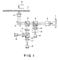
- optical head of a conventional apparatus of this type there is an optical head for a magneto-optical disk as shown, for example, in Figure 1 of the accompanying drawings.
- the reference numeral 1 designates a semiconductor laser which is a light source, and the laser light from the semiconductor laser 1 is made into a parallel light beam by a collimator lens 2. Most of the parallel light beam is transmitted through the beam splitter 3 of a servo optical system and the beam splitter 4 of a main optical system, and thereafter is deflected by a galvano mirror 5 and enters an objective lens 6.
- the parallel beam which has entered the objective lens 6 is condensed by the objective lens 6, and the condensed light beam forms a light spot of a diameter of about 1 ⁇ m on the medium surface (the vertically magnetized film) of a disk 7 which is a recording medium.
- the reflected light of the light spot is received by light receiving elements 12 and 13 through the objective lens 6, the galvano mirror 5, the beam splitter 4 of the main optical system, a half wavelength plate 9, a polarizing beam splitter 10 and imaging lenses 11 and 11′, and the Kerr rotation of the reflected light is detected from the differential output of the light receiving elements 12 and 13 to thereby reproduce the information.
- the main optical system is constituted by the beam splitter 4, the half wavelength plate 9, the polarizing beam splitter 10 and the imaging lenses 11 and 11′.
- the reference numeral 16 denotes a light receiving element for receiving the reflected light from the beam splitter 3 of the servo optical system through an imaging optical system 15 having an imaging lens 14 for auto focusing and auto tracking, i.e. a sensor for servo.
- the servo optical system is constituted by the beam splitter 3 and the imaging optical system 15.
- the beam splitter 3 or 4 used in the conventional optical head constructed as described above has a reflecting surface as shown in Figure 2 of the accompanying drawings.
- the optic axis of a light beam passing through an imaging optical system, not shown, to the sensor 16 for servo is inclined by 2 ⁇ .
- the optic axis is inclined and therefore, the light beam moves on the light receiving surface of the sensor 16 for servo. Assuming that the amount of movement is ⁇ ′2, ⁇ ′2 ⁇ 2f ⁇ , where f is the focal length of the imaging lens.
- the optical head of the optical disk apparatus effects focusing servo and tracking servo to accurately record, reproduce and erase information on the tracks of the disk-like recording medium, and high accuracy is required of all these operations. It has therefore been necessary to minimize the error of the applied position of the light beam on the surface of the light receiving element.
- the beam splitter 3 of the servo optical system when for example, the beam splitter 3 of the servo optical system is to be mounted and fixed at a predetermined position, an adhesive agent is used and the work is done with considerable care paid to the positional relation thereof, but the work of course involves a high degree of difficulty, as well as expansion or contraction because of a temperature change or a variation with time after the fixing.
- the present invention proposes, as means for solving problems in an optical disk apparatus wherein a light beam from a light source is made into a parallel beam by a collimator optical system and the parallel beam is applied as a beam spot to a disk-like recording medium by an objective optical system to thereby effect the recording and reproduction of information, the provision of at least one branch-off means disposed between the collimator optical system for making the light beam from said light source into a parallel light beam and said objective optical system and provided with an even number of reflecting surfaces.
- a beam splitter for reflecting the light beam an even number of times by reflecting surfaces parallel or orthogonal to each other is disposed in the optical path of the optical head and therefore, even if some displacement occurs to said beam splitter, there is not the inconvenience as is peculiar to the prior art that the applied position of the beam on the light receiving surface is greatly displaced and offset or cross talk strain or the like occurs.
- Figure 3 shows a state in which the beam splitter has been displaced in the direction of the optic axis (the Z direction) and a direction orthogonal to the optic axis.
- a light emitted from a light source is transmitted through the beam splitter 30, is made into a spot light through an optical system, not shown, and is applied to a recording medium.
- the reflected light from the recording medium again enters the beam splitter 30 through said optical system. Since even when the beam splitter 30 is displaced in the direction of the optic axis and a direction orthogonal to the optic axis, the two reflecting surfaces thereof are provided so as to be parallel to each other, the applied position of the light beam which has again entered the beam splitter 30 and enters a light receiving element 16 does not change.
- Figure 4 shows a state in which the beam splitter is inclined by an angle ⁇ ( ⁇ « 1).
- the light beam which enters the light receiving element 16 effects parallel movement as compared with the time before it rotates. Assuming that the amount of movement thereof is ⁇ , ⁇ ⁇ l ⁇ /n, where n is the refractive index of the material of the optical part. In Figure 4, the bending of the optical path caused by the light obliquely entering the beam splitter is not shown.
- the light receiving position changes by ⁇ .
- the light beam effects parallel movement and the amount of movement thereof is small. Also, in the construction of the optical head of the present apparatus in which an imaging lens is provided for focusing, any change does not occur in the light receiving position for the light beam on the light receiving surface.
- Figure 5 shows a first embodiment of the present invention.
- a light from a light source 1 is made into a parallel light beam by a collimator lens 2.
- Most of the parallel light beam is transmitted through the beam splitter 30 of a servo optical system and the beam splitter of a main optical system, not shown, is deflected by a galvano mirror, not shown, and enters an objective lens 6.
- the parallel beam which has entered the objective lens 6 is condensed by the objective lens 6, and the condensed light beam forms a light spot on a disk 7 which is a recording medium.
- the reflected light of the light spot again passes through said optical systems and enters the beam splitter 30 of the servo optical system to effect focusing servo and tracking servo.
- the light beam which has entered the beam splitter 30 of the servo optical system is reflected by two reflecting surfaces provided parallel to each other and passes through an imaging optical system 15, and is imaged on the light receiving surface of a sensor 16 for servo by an imaging lens 14 in the imaging optical system 15.
- the light beam is reflected by the two reflecting surfaces of the beam splitter 30 which are provided parallel to each other, and thereafter is imaged by the imaging lens 14 and therefore, the light beam is received at the same position on the light receiving surface of the sensor 16 for servo without being affected by the displacement or inclination of the beam splitter 30.
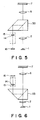
- Figure 6 shows a second embodiment of the present invention.
- a beam splitter 33 having two reflecting surfaces orthogonal to each other, and a light beam may be reflected by the reflecting surfaces so that the light beam may be imaged on the light receiving surface of a sensor 16 for servo by an imaging lens 14 in an imaging optical system 15.
- the light receiving effect for the reflected light of the light spot is similar to that in the first embodiments.
- the substance of carrying out the invention has been described with respect to the servo optical system, whereas this is not restrictive, but of course, the present invention can also be carried out in the main optical system (the optical system for information reproduction).
- the present invention is not limited by the difference in the kind of the optical head, i.e., the difference as between a magneto-optical head and a write once head.
- an even number of reflecting surfaces are provided in a beam splitter and therefore, no hindrance will be brought about in the detection of the reflected light even if some displacement and inclination occur to the beam splitter, and this leads to not only the advantage that the adjusting work for high accuracy becomes easy, but also the advantage that the occurrence of an accident resulting from the displacement and inclination of the baem splitter caused thereafter by some external factors is eliminated.
- the method of fixing the beam splitter may be the fixing method which is usually practised, and it becomes unnecessary to employ such a special treatment that no displacement will be caused.
Landscapes
- Physics & Mathematics (AREA)
- Optics & Photonics (AREA)
- Optical Head (AREA)
Applications Claiming Priority (2)
| Application Number | Priority Date | Filing Date | Title |
|---|---|---|---|
| JP123267/89 | 1989-05-17 | ||
| JP1123267A JPH02302941A (ja) | 1989-05-17 | 1989-05-17 | 光ディスク装置の光ヘッド |
Publications (2)
| Publication Number | Publication Date |
|---|---|
| EP0398622A2 true EP0398622A2 (de) | 1990-11-22 |
| EP0398622A3 EP0398622A3 (de) | 1991-12-18 |
Family
ID=14856334
Family Applications (1)
| Application Number | Title | Priority Date | Filing Date |
|---|---|---|---|
| EP19900305191 Withdrawn EP0398622A3 (de) | 1989-05-17 | 1990-05-15 | Optischer Kopf für einen optischen Plattenspieler |
Country Status (2)
| Country | Link |
|---|---|
| EP (1) | EP0398622A3 (de) |
| JP (1) | JPH02302941A (de) |
Family Cites Families (4)
| Publication number | Priority date | Publication date | Assignee | Title |
|---|---|---|---|---|
| JPS5971141A (ja) * | 1982-10-14 | 1984-04-21 | Mitsubishi Electric Corp | 光学的信号読出し装置 |
| JPS59175041A (ja) * | 1983-03-24 | 1984-10-03 | Mitsubishi Electric Corp | 光学ヘツド装置 |
| US4853923A (en) * | 1985-12-12 | 1989-08-01 | Nikon Corporation | Maneto-optical recording apparatus with path length compensated dual photo-electric conversion |
| JP2601805B2 (ja) * | 1986-09-26 | 1997-04-16 | オリンパス光学工業株式会社 | 光学式ピツクアツプ |
-
1989
- 1989-05-17 JP JP1123267A patent/JPH02302941A/ja active Pending
-
1990
- 1990-05-15 EP EP19900305191 patent/EP0398622A3/de not_active Withdrawn
Also Published As
| Publication number | Publication date |
|---|---|
| EP0398622A3 (de) | 1991-12-18 |
| JPH02302941A (ja) | 1990-12-14 |
Similar Documents
| Publication | Publication Date | Title |
|---|---|---|
| US4644516A (en) | Optical head | |
| US5131744A (en) | Mirror rotation angle detection mechanism | |
| EP0418087B1 (de) | Optischer Kopf | |
| EP0189932B1 (de) | Spurfolgesystem zum steuerbaren Projizieren eines optischen Strahles auf eine optische Platte | |
| US4785438A (en) | Magneto-optical disc reproducing apparatus with improved two-part head | |
| US4804835A (en) | Optical head having guide means with first and second polarizing surfaces | |
| US4273998A (en) | Servo unit for optical type information reading device | |
| EP0164687B1 (de) | Optischer Kopf zur Fokussierung eines Lichtbündels auf einer optischen Platte | |
| US4290132A (en) | Focus servo device for use in an optical information read-out device | |
| EP0399650B1 (de) | Keilförmige prismatische Anordnung zur optischen Informatonsspeicherung | |
| KR900000018B1 (ko) | 광 헤 드 | |
| US4977552A (en) | Split type optical pick-up device with a tracking error detector on the moving part | |
| EP0339940A2 (de) | Optische Abtastvorrichtung | |
| EP0543505B1 (de) | Optischer Kopf mit Mehrfachstrahl | |
| JPH10255304A (ja) | 光学ピックアップ用対物レンズの調整方法及び調整装置 | |
| EP0398622A2 (de) | Optischer Kopf für einen optischen Plattenspieler | |
| JPS62132242A (ja) | 光デイスク装置 | |
| US5615181A (en) | Optical read/write head with low angle beam splitter and coplanar detectors | |
| EP0640961A1 (de) | Gerät zur Verwendung in der Einstellung eines optischen Kopfes | |
| HUT62419A (en) | Optical scanner | |
| JP2629456B2 (ja) | 対物レンズ位置検出装置 | |
| JP3656936B2 (ja) | 光ディスク装置の光学系 | |
| JP3006987B2 (ja) | 光ピックアップ | |
| JPS5841448A (ja) | 光学的焦点位置移動方式 | |
| JP2629457B2 (ja) | 対物レンズ位置検出装置 |
Legal Events
| Date | Code | Title | Description |
|---|---|---|---|
| PUAI | Public reference made under article 153(3) epc to a published international application that has entered the european phase |
Free format text: ORIGINAL CODE: 0009012 |
|
| AK | Designated contracting states |
Kind code of ref document: A2 Designated state(s): DE FR GB IT |
|
| PUAL | Search report despatched |
Free format text: ORIGINAL CODE: 0009013 |
|
| AK | Designated contracting states |
Kind code of ref document: A3 Designated state(s): DE FR GB IT |
|
| STAA | Information on the status of an ep patent application or granted ep patent |
Free format text: STATUS: THE APPLICATION IS DEEMED TO BE WITHDRAWN |
|
| 18D | Application deemed to be withdrawn |
Effective date: 19920619 |