EP0398630A2 - Moteur d'essuie-glace - Google Patents
Moteur d'essuie-glace Download PDFInfo
- Publication number
- EP0398630A2 EP0398630A2 EP90305201A EP90305201A EP0398630A2 EP 0398630 A2 EP0398630 A2 EP 0398630A2 EP 90305201 A EP90305201 A EP 90305201A EP 90305201 A EP90305201 A EP 90305201A EP 0398630 A2 EP0398630 A2 EP 0398630A2
- Authority
- EP
- European Patent Office
- Prior art keywords
- contact
- contact plate
- stopping
- gear
- shoe
- Prior art date
- Legal status (The legal status is an assumption and is not a legal conclusion. Google has not performed a legal analysis and makes no representation as to the accuracy of the status listed.)
- Withdrawn
Links
Images


Classifications
-
- B—PERFORMING OPERATIONS; TRANSPORTING
- B60—VEHICLES IN GENERAL
- B60S—SERVICING, CLEANING, REPAIRING, SUPPORTING, LIFTING, OR MANOEUVRING OF VEHICLES, NOT OTHERWISE PROVIDED FOR
- B60S1/00—Cleaning of vehicles
- B60S1/02—Cleaning windscreens, windows or optical devices
- B60S1/04—Wipers or the like, e.g. scrapers
- B60S1/06—Wipers or the like, e.g. scrapers characterised by the drive
- B60S1/08—Wipers or the like, e.g. scrapers characterised by the drive electrically driven
-
- Y—GENERAL TAGGING OF NEW TECHNOLOGICAL DEVELOPMENTS; GENERAL TAGGING OF CROSS-SECTIONAL TECHNOLOGIES SPANNING OVER SEVERAL SECTIONS OF THE IPC; TECHNICAL SUBJECTS COVERED BY FORMER USPC CROSS-REFERENCE ART COLLECTIONS [XRACs] AND DIGESTS
- Y10—TECHNICAL SUBJECTS COVERED BY FORMER USPC
- Y10S—TECHNICAL SUBJECTS COVERED BY FORMER USPC CROSS-REFERENCE ART COLLECTIONS [XRACs] AND DIGESTS
- Y10S318/00—Electricity: motive power systems
- Y10S318/02—Windshield wiper controls
Definitions
- This invention relates to a windshield wiper motor used for driving a wiper linkage to wipe rain drops and the like on a windshield surface.
- a windshield wiper motor 101 shown in Figure 8 is equipped with an armature 102 and reduction gear 103 for reducing rotational speed of said armature 102, and equipped with an auto-stopping switch 105 for stopping a wiper blade A shown in Figure 7 at a stopping positon securely to a worm wheel that is the final gear of said reduction gear 103.
- Said auto-stopping switch 105 is disposed with a circular first contact plate 110 cut off in fan-like shape at a part thereof and a second contact plate 111 positioned in the cutout portion of said first contact plate 110, separated from said first contact plate 110 and jutting out from the outer periphery of said first contact plate 110 on one side of said worm wheel, and is equipped with a first contact 113 connected to a power source 112 and an armature 102 and possible to contact only with said second contact plate 111 and a second contact 115 connected to an OFF-terminal 114a of a wiper switch 114 and possible to contact with both said first and second contact plates 110 and 111.
- the wiper blade A is driven in the vincinity of the stopping position by continuing the power supply to the armature 102 because the second contact 115 of the auto-stopping switch 105 is in contact with the first contact plate 110 and grounded when the wiper blade A is not sited at the stopping possition shown with a solid line in Figure 7. And the power supply to the motor is cut off when the second contact 115 separetes from the first contact plate 110, however the wiper blade A is further moved by the inertial force.
- the position in which the wiper blade A hits against the gathered snow corresponds to a position in which the second contact 115 of the auto-stopping switch 105 is switched over from the contact with the first contact plate 110 to the contact with the second contact plate 111, said second contact 115 is in contact with a space between the first and second contact plates 110 and 111 and the armature 102 is in a state the power supply is cut off. Accordingly, the second contact 115 touches again the first contact plate 110 by the reaction from the gathered snow and the armature 102 is supplied with electric power, and a phenomenon that the wiper blade A hits repeatedly against the snow by the rotation of said armature 102 and the reaction from the snow, that is, chattering occures.
- the second contact 115 of the auto-stopping switch 105 sparks every time it touches the first contact plate 110 and the resinous worm wheel is deformed partially owing to the heat caused by sparking, there is a problem since the working of the windshield wiper motor 101 may be hindered by the deformation of the worm wheel.
- the present invention seeks to provide a windshield wiper motor which is possible to prevent a auto-stopping switch from the chattering phenomenon even if a wiper blade is returned as a reaction form snow gathered in the vicinity of the stopping position of said wiper blade in snowfall.
- the windshield wiper motor according to claim 1 of this invention comprises an electric motor part, a gear case connected with said motor part and housing reduction gear for reducing rotational speed of an armature of said motor part and an auto-stopping switch provided to said gear case and for driving an output shaft of said reduction gear to a fixed stopping position and stopping the armature of said motor part at said stopping position by dynamic braking according to OFF-operation of a wiper switch, and is characterized by having a construction that said auto-stopping switch is provided with a first contact plate connected to a grounding conductor, a second contact plate connected to a power source and a third contact plate connected to a line terminal of the motor part on the inner surface of a gear cover, and provided with a contact shoe for contacting with said third contact plate at all times and for contacting with said first or second contact plate selectively by sliding on a straight line reciprocatively in accordance with rotation of the final gear of said reduction gear.
- the aforementioned construction of the windshield wiper motor is taken as a measure to solve the a
- the windshield wiper motor according to claim 2 of this invention is characterized by having a construction that said contact shoe is provided with a first protrusion for sliding said contact shoe into predetermined direction on a guide groove in contact with a C-like shaped first projection disposed on the final gear of said reduction gear, a second protrusion for sliding said contact shoe into another side on the guide groove in contact with a second projection disposed on the inner side of said first projection, a first contact for contacting selectively with the first or second contact plate, and a second contact for contacting with the third contact plate at all times in the windshield wiper motor according to claim 1.
- the aforementioned construction of the windshield wiper motor is taken as a measure to solve the aforementioned problem of the prior art.
- the windshield wiper motor according to claim 1 of this invention is so constructed as to slide the contact shoe of the auto-stopping switch on the straight line reciprocatively in accordance with the rotation of the final gear of the reduction gear. Therefore, the first contact plate is connected electrically with the third contact plate when said contact shoe is in contact with the first contact plate, and the wiper blade is driven to the fixed stopping position by continuing the power supply to the armature. And the second contact plate is connected electrically with the third contact plate when said contact shoe is in contact with the second contact plate, and the wiper blade is stopped at the stopping position by braking the armature dynamically.
- the windshield wiper motor according to claim 2 of this invention is so constructed as to slide said contact shoe into predetermined direction on a guide groove by contacting the first protrusion of the contact shoe with the C-shaped projection disposed on the final gear of the reduction gear and to slide said contact shoe into another side on the guide groove by contacting the second protrusion of the contact shoe with the second projection on the final gear of the reduction gear. Therefore, the contacting period of the first contact plate with the third contact plate and the contacting periode of the second contact plate with the third contact plate are controlled by adjusting the lengths of the first and second projections in the circumferential direction.
- FIGS. 1 to Figure 7 are diagrams showing an embodiment of the windshield wiper motor according to this invention
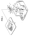
- Figure 1 and Figure 2 are an exploded perspective view and a partially sectional view illustrating the construction of the windshield wiper motor.
- a windshield wiper motor 1 shown in Figure 1 and Figure 2 has a construction comprising an electric motor part 2, a gear case 5 connected with said motor part 2 and housing reduction gear 4 for reducing rotational speed of an armature 3 of said motor part 2, and an auto-stopping switch 7 provided to said reduction gear 4 and for driving a wiper blade A shown in Figure 7 and connected to an output shaft 6 of the reduction gear 4 through a wiper linkage to a fixed stopping position and stopping said wiper blade A at said stopping position by dynamic braking according to OFF-operation of a wiper switch (not shown).
- Said reduction gear 4 has a construction comprising a worm 11 formed on a tip end of an armature shaft 10 by rolling, a worm wheel 12 engaged with said worm 11, an intermediate gear 13 formed in one body with said worm wheel 12 coaxially and the final gear 14 connected with said output shaft 6 coaxially and engaged with said intermediate gear 13.
- Said auto-stopping switch 7 has a construction comprising a C-like shaped first projection disposed on the upper surface of the final gear 14 of the reduction gear 4, a second projection 21 disposed on the inner side of said first projection 20, a first contact plate 22 diposed on the inner surface of a gear cover 5a and connected to a grounding conductor, a second contact plate 23 disposed in parallel to said first contact plate 22 with a space and connected to the positive terminal of a power source, long-shaped third contact plate 24 shifted from said first contact plate 22 to be switched over into positive or negative polarity by said contact plates 22 and 23, and a contact shoe 25 made of electrically conductive material and for contacting always with said third contact plate 24 and contacting selectively with said first or second contact plate 22 or 23 by sliding reciprocatively on a straight line in contact with said first and second projections 20 and 21 from the circumferential direction.
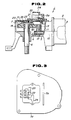
- Said contact shoe 25 has a construction comprising, as shown also in Figure 4 and Figure 5, a guide 30 for sliding reciprocatively on the straight line by engaging with a guide groove 5b provided on the inner surface of said gear cover 5a, a first protrusion 31 formed in bent downwardly in Figure 5 for sliding said contact shoe 25 into predetermined direction on the guide groove 5b in contact with said first projection 20, a second projection 32 formed in bent downwardly in Figure 5 for sliding said contact shoe 25 into another side on the guide groove 5b in contact with said second projection 21, a first contact 33 for cotnacting with said first or second contact plates 22 or 23 selectively by the reciprocative slide on the straight line of said contact shoe 25 through said first and second protrusions 31 and 32, a second contact 34 for contacting with said third contact plate 24 at all times, and a third contact 35 in contact with the inner surface of the gear cover 5a together with said first contact 33 for energizing said contact shoe 25 downwardly in Figure 2. Furthermore, pin-like rivets 33a and 34a are attached to the tip ends of
- the contact shoe 25 is possible to be maintained in the position as it is even if the wiper blade A is returned in the opposite direction as a reaction from the snow gathered in the vicinity of the stopping position by the hitting of said wiper blade A against the snow in snowfall, that is, even if the output shaft rotates in the clockwise direction.
- the power supply to the armature 3 is continued by the auto-stopping switch 7 until the wiper blade A reaches to the stopping position in the case the OFF-operation of the wiper switch is done, and when the wiper blade A reaches to the fixed stopping position, the auto-stopping switch 7 brakes the armature 3 dynamically and the wiper blade A is stopped similarly to the auto-stopping switch of the conventional windshield wiper motor.
- the problem such as chattering never arises differing from the conventional windshield wiper motor because the reverse rotation of the final gear 14 is not transmitted to the contact sheo 25 even if the output shaft 6 rotates in the opposite direction.
- the windshield wiper motor according to claim 1 of this invention comprises an electric motor part, a gear case connected with said motor part and housing reduction gear for reducing rotational speed of an armature of said motor part and an auto-stopping switch provided to said gear case and for driving an output shaft of said reduction gear to a fixed stopping position and stopping the armature of said motor part at said stopping position by dynamic braking according to OFF-operation of a wiper switch
- said auto-stopping switch is provided with a first contact plate connected to a grounded conductor, a second contact plate connected to a power source and a third contact plate connected to a line terminal of the motor part on the inner surface of a gear cover, and provided with a contact shoe in contact with said third contact plate at all times and in contact with said first or second contact plate selectively by sliding on a straight line reciprocatively in accordance with rotation of the final gear of said reduction gear.
- the windshield wiper motor according to claim 2 of this invention has the contact shoe provided with a first protrusion for sliding said contact shoe into predetermined direction on a guide groove in contact with a C-like shaped first projection disposed on the final gear of said reduction gear, a second protrusion for sliding said contact shoe into another side on the guide groove in contact with a second projection disposed on the inner side of said first projection, a first contact for contacting selectively with the first or second contact plate, and a second contact for contacting with the third contact plate at all times in the windshield wiper motor according to claim 1.
- the contact shoe of the auto-stopping switch stays at the position as it is even if the wiper blade is returned as a reaction from snow gathered in the vicinity of the stopping position of the wiper blade in snowfall, because the contact shoe is slided into one side on the guide groove by contacting the first protrusion of the contact shoe with the C-like shaped first projection and slided into another side on the guide groove by contacting the second protrusion of contact shoe with the second projection. Accordingly, an excellent effect can be obtained since it is possible to prevent the chattering caused by the reverse rotation of the final gear in addition to the effect of the invention claimed in claim 1.
Landscapes
- Engineering & Computer Science (AREA)
- Mechanical Engineering (AREA)
- Connection Of Motors, Electrical Generators, Mechanical Devices, And The Like (AREA)
- Mechanisms For Operating Contacts (AREA)
- Stopping Of Electric Motors (AREA)
- Slide Switches (AREA)
Applications Claiming Priority (2)
| Application Number | Priority Date | Filing Date | Title |
|---|---|---|---|
| JP56302/89U | 1989-05-16 | ||
| JP1989056302U JPH02145552U (fr) | 1989-05-16 | 1989-05-16 |
Publications (2)
| Publication Number | Publication Date |
|---|---|
| EP0398630A2 true EP0398630A2 (fr) | 1990-11-22 |
| EP0398630A3 EP0398630A3 (fr) | 1992-11-19 |
Family
ID=13023334
Family Applications (1)
| Application Number | Title | Priority Date | Filing Date |
|---|---|---|---|
| EP19900305201 Withdrawn EP0398630A3 (fr) | 1989-05-16 | 1990-05-15 | Moteur d'essuie-glace |
Country Status (3)
| Country | Link |
|---|---|
| US (1) | US5023530A (fr) |
| EP (1) | EP0398630A3 (fr) |
| JP (1) | JPH02145552U (fr) |
Cited By (5)
| Publication number | Priority date | Publication date | Assignee | Title |
|---|---|---|---|---|
| DE19609973A1 (de) * | 1996-03-14 | 1997-09-18 | Teves Gmbh Alfred | Antriebsvorrichtung für Scheibenwischer mit einem Parkstellungsschalter |
| US6304047B1 (en) * | 1999-05-20 | 2001-10-16 | Asmo Co., Ltd. | Wiper motor control apparatus |
| US6351088B1 (en) | 2000-03-09 | 2002-02-26 | Valeo Electrical Systems, Inc. | Non-reversing wiper park switch for wiper drive apparatus |
| US6737593B1 (en) | 2000-07-28 | 2004-05-18 | Valeo Electrical Systems, Inc. | Non-reversing windshield wiper motor park switch |
| US20090113652A1 (en) * | 2006-05-24 | 2009-05-07 | Dongyang Mechatronics Corp. | Wiper driving apparatus for automobile |
Families Citing this family (36)
| Publication number | Priority date | Publication date | Assignee | Title |
|---|---|---|---|---|
| JP2571803Y2 (ja) * | 1991-05-30 | 1998-05-20 | ナイルス部品株式会社 | モータアクチュエータの動作位置検出機構 |
| US5764010A (en) * | 1995-04-28 | 1998-06-09 | United Technologies Automotive, Inc. | Control system for an automotive vehicle multi-functional apparatus |
| US5949206A (en) * | 1995-04-28 | 1999-09-07 | Ut Automotive Dearborn, Inc. | Multi-functional apparatus employing an intermittent motion mechanism |
| US5903114A (en) * | 1995-04-28 | 1999-05-11 | Ut Automotive Dearborn, Inc. | Multi-functional apparatus employing an intermittent motion mechanism |
| US6111378A (en) * | 1995-04-28 | 2000-08-29 | Ut Automotive Dearborn, Inc. | Window wiper motor system for an automotive vehicle |
| US5841249A (en) * | 1995-04-28 | 1998-11-24 | Ut Automotive Dearborn, Inc. | Multi-functional apparatus employing an intermittent motion mechanism |
| US5920158A (en) * | 1995-04-28 | 1999-07-06 | Miller; Robin Mihekun | Multi-functional vehicle apparatus |
| US5694812A (en) * | 1995-04-28 | 1997-12-09 | United Technologies Automotive, Inc. | Multi-functional apparatus employing an electromagnetic device and an intermittent motion mechanism |
| US5916327A (en) * | 1995-04-28 | 1999-06-29 | Ut Automotive Dearborn, Inc. | Multi-functional apparatus employing an electromagnetic device |
| US5844382A (en) * | 1997-04-09 | 1998-12-01 | Ut Automotive Dearborn, Inc | Motion transmitting apparatus for use with an automotive vehicle multi-functional apparatus |
| US5979255A (en) * | 1997-04-09 | 1999-11-09 | Lear Automotive Dearborn, Inc. | Intermittent rotary motion mechanism for use in an automotive vehicle |
| US5969431A (en) * | 1997-10-08 | 1999-10-19 | Lear Automotive Dearborn, Inc. | Linearly actuating multi-functional apparatus for use in an automotive vehicle |
| US6002323A (en) * | 1997-10-09 | 1999-12-14 | Lear Automotive Dearborn, Inc. | Audible feedback apparatus for indicating operation and position of a movable element |
| US5889341A (en) * | 1997-10-09 | 1999-03-30 | Ut Automotive Dearborn, Inc. | Multi-functional apparatus employing a linear wiper |
| US6003193A (en) * | 1997-10-09 | 1999-12-21 | Lear Automotive Dearborn, Inc. | Multi-functional apparatus having flexible clutch |
| US5920949A (en) * | 1997-10-09 | 1999-07-13 | Ut Automotive Dearborn, Inc. | Rocking wiper mechanism |
| US5953786A (en) * | 1997-10-09 | 1999-09-21 | Ut Automotive Dearborn, Inc. | Bypass loop wiper/washer system |
| US5986351A (en) * | 1997-10-09 | 1999-11-16 | Lear Automotive Dearborn, Inc. | Bi-directional lever for activating automotive liftgate lock mechanism |
| US5977678A (en) * | 1997-10-09 | 1999-11-02 | Ut Automotive Dearborn, Inc. | Magnetic coupling mechanism for use in an automotive vehicle |
| US5907885A (en) * | 1997-10-09 | 1999-06-01 | Ut Automotive Dearborn, Inc. | Multi-functional apparatus for use in an automotive vehicle employing multiple tracks |
| US5907199A (en) * | 1997-10-09 | 1999-05-25 | Ut Automotive Dearborn, Inc. | Electric motor providing multi-directional output |
| US5847519A (en) * | 1997-10-09 | 1998-12-08 | Ut Automotive Dearborn, Inc. | Multi-functional apparatus for a wiper and cable drive |
| US5917298A (en) * | 1997-10-09 | 1999-06-29 | Ut Automotive Dearborn, Inc. | Electric motor control system with resistor network for automobile wiper assembly |
| US6075298A (en) * | 1997-10-09 | 2000-06-13 | Lear Automotive Dearborn, Inc | Rotary and linear translation actuator performing multi-functions in an automobile |
| US5924324A (en) * | 1997-10-09 | 1999-07-20 | Ut Automotive Dearborn, Inc. | Movable gear drive windshield wiper |
| US6026536A (en) * | 1997-10-09 | 2000-02-22 | Lear Automotive Dearborn, Inc | Range limiting dual direction slip clutch |
| US5929588A (en) * | 1997-10-09 | 1999-07-27 | Ut Automotive Dearborn, Inc. | Electric motor control system for automobile wiper assembly |
| US5979256A (en) * | 1997-10-09 | 1999-11-09 | Ut Automotive Dearborn, Inc. | Gear drive window wiper and multi-function electric motor |
| US5981907A (en) * | 1997-10-09 | 1999-11-09 | Ut Automotive Dearborn, Inc. | Rear wiper monitoring theft deterrent circuit |
| US6020576A (en) * | 1997-10-09 | 2000-02-01 | Lear Automotive Dear Born, Inc. | Temperature and windshield crack detector |
| US5920159A (en) * | 1997-10-09 | 1999-07-06 | Ut Automotive Dearborn, Inc. | Multi-functional apparatus employing a flexible drive element for selectively actuating multiple output systems |
| US6205612B1 (en) | 1997-10-09 | 2001-03-27 | Ut Automotive Dearborn, Inc. | Window wiper system for an automotive vehicle |
| CZ301606B6 (cs) * | 2004-10-25 | 2010-04-28 | Iqi S.R.O. | Zpusob ovládání stírátek u automobilových steracových systému prostrednictvím rízení elektrického motoru s kývavým pohybem jeho výstupní hrídele a úprava tohoto elektrického motoru |
| CN203410424U (zh) * | 2013-08-20 | 2014-01-29 | 博世汽车部件(长沙)有限公司 | 雨刮电驱动装置及其输出齿轮组件 |
| DE102014201149A1 (de) * | 2014-01-22 | 2015-07-23 | Robert Bosch Gmbh | Antriebseinrichtung für eine Scheibenwischvorrichtung |
| US10889267B2 (en) * | 2018-03-05 | 2021-01-12 | Tesla, Inc. | Electromagnetic windshield wiper system |
Family Cites Families (9)
| Publication number | Priority date | Publication date | Assignee | Title |
|---|---|---|---|---|
| US3253206A (en) * | 1963-12-23 | 1966-05-24 | Gen Motors Corp | Windshield wiper actuating mechanism |
| DE2803264A1 (de) * | 1978-01-26 | 1979-08-02 | Bosch Gmbh Robert | Scheibenwischvorrichtung fuer fahrzeuge |
| US4350938A (en) * | 1981-09-04 | 1982-09-21 | Equipements Automobiles Marchal | Travel limit stop device for a motor-reducing unit intended in particular for a window wiper |
| US4455511A (en) * | 1983-03-04 | 1984-06-19 | Ambac Industries, Incorporated | Windshield wiper mechanism |
| DE3434060A1 (de) * | 1983-09-22 | 1985-04-11 | Jidosha Denki Kogyo K.K., Yokohama, Kanagawa | Steuervorrichtung zum anhalten eines scheibenwischers |
| US4613733A (en) * | 1984-10-02 | 1986-09-23 | United Technologies Automotive, Inc. | Delay wiper switch |
| US4673853A (en) * | 1985-01-18 | 1987-06-16 | Asmo Co., Ltd. | Concealed wiper system |
| JPH0411887Y2 (fr) * | 1985-05-24 | 1992-03-24 | ||
| US4609794A (en) * | 1985-08-30 | 1986-09-02 | Ford Motor Company | Printed circuit switch for windshield wiper motor |
-
1989
- 1989-05-16 JP JP1989056302U patent/JPH02145552U/ja active Pending
-
1990
- 1990-05-15 US US07/523,960 patent/US5023530A/en not_active Expired - Fee Related
- 1990-05-15 EP EP19900305201 patent/EP0398630A3/fr not_active Withdrawn
Cited By (7)
| Publication number | Priority date | Publication date | Assignee | Title |
|---|---|---|---|---|
| DE19609973A1 (de) * | 1996-03-14 | 1997-09-18 | Teves Gmbh Alfred | Antriebsvorrichtung für Scheibenwischer mit einem Parkstellungsschalter |
| WO1997033779A1 (fr) * | 1996-03-14 | 1997-09-18 | Itt Manufacturing Enterprises, Inc. | Dispositif d'entrainement pour essuie-glace muni d'un commutateur d'arret fixe |
| US6304047B1 (en) * | 1999-05-20 | 2001-10-16 | Asmo Co., Ltd. | Wiper motor control apparatus |
| US6351088B1 (en) | 2000-03-09 | 2002-02-26 | Valeo Electrical Systems, Inc. | Non-reversing wiper park switch for wiper drive apparatus |
| US6737593B1 (en) | 2000-07-28 | 2004-05-18 | Valeo Electrical Systems, Inc. | Non-reversing windshield wiper motor park switch |
| US20090113652A1 (en) * | 2006-05-24 | 2009-05-07 | Dongyang Mechatronics Corp. | Wiper driving apparatus for automobile |
| US8296896B2 (en) * | 2006-05-24 | 2012-10-30 | Dongyang Mechatronics Corp | Wiper driving apparatus for automobile |
Also Published As
| Publication number | Publication date |
|---|---|
| EP0398630A3 (fr) | 1992-11-19 |
| US5023530A (en) | 1991-06-11 |
| JPH02145552U (fr) | 1990-12-11 |
Similar Documents
| Publication | Publication Date | Title |
|---|---|---|
| US5023530A (en) | Windshield wiper motor | |
| JP2000506100A (ja) | パーク位置スイッチを備えた風防ワイパー用駆動装置 | |
| RU2000122363A (ru) | Ручное бытовое электрическое устройство для привода рабочего инструмента | |
| US5075519A (en) | Windshield wiper switch | |
| US5654616A (en) | Windshield wiper system with soft wipe mode for high speed operation | |
| EP0359227A2 (fr) | Appareil d'entraînement d'essuie-glace | |
| GB2052099A (en) | Control of wiper drive | |
| US2499298A (en) | Windshield wiper | |
| US5981886A (en) | Multifunction switch assembly | |
| US2335424A (en) | Windshield wiper parking device | |
| JPH04224442A (ja) | ワイパ制御装置 | |
| EP0210762A1 (fr) | Essuie-glaces | |
| US2899510A (en) | R merriam | |
| KR100521986B1 (ko) | 자동차의 와이퍼 스위치 | |
| EP0147235B1 (fr) | Appareil pour entraîner un essuie-glace | |
| KR100422681B1 (ko) | 자동차용와이퍼 | |
| EP0279786B1 (fr) | Dispositif essuie-glace pour le pare-brise ou la vitre arrière, en particulier d'une automobile | |
| US4929876A (en) | Electric windshield wiping apparatus | |
| JPS5878848A (ja) | 車両用ワイパの制御方法および装置 | |
| SU1799485A3 (ru) | Пуteboй bыkлючateль | |
| PL210368B1 (pl) | Silnik elektryczny wycieraczki z układem z tarczą stykową | |
| CN1404613A (zh) | 电气开关 | |
| JP2881042B2 (ja) | 駆動モータ | |
| JP2002523277A (ja) | ウインドガラスワイパ装置 | |
| EP1428721A2 (fr) | Dispositif commutateur multiple |
Legal Events
| Date | Code | Title | Description |
|---|---|---|---|
| PUAI | Public reference made under article 153(3) epc to a published international application that has entered the european phase |
Free format text: ORIGINAL CODE: 0009012 |
|
| AK | Designated contracting states |
Kind code of ref document: A2 Designated state(s): DE FR GB |
|
| PUAL | Search report despatched |
Free format text: ORIGINAL CODE: 0009013 |
|
| AK | Designated contracting states |
Kind code of ref document: A3 Designated state(s): DE FR GB |
|
| STAA | Information on the status of an ep patent application or granted ep patent |
Free format text: STATUS: THE APPLICATION IS DEEMED TO BE WITHDRAWN |
|
| 18D | Application deemed to be withdrawn |
Effective date: 19930520 |