EP0398718A2 - Dichtungssystem für Feststoffrückführung in einem Wirbelbettreaktor - Google Patents
Dichtungssystem für Feststoffrückführung in einem Wirbelbettreaktor Download PDFInfo
- Publication number
- EP0398718A2 EP0398718A2 EP90305339A EP90305339A EP0398718A2 EP 0398718 A2 EP0398718 A2 EP 0398718A2 EP 90305339 A EP90305339 A EP 90305339A EP 90305339 A EP90305339 A EP 90305339A EP 0398718 A2 EP0398718 A2 EP 0398718A2
- Authority
- EP
- European Patent Office
- Prior art keywords
- fluidized bed
- section
- particulate material
- sealing section
- bed
- Prior art date
- Legal status (The legal status is an assumption and is not a legal conclusion. Google has not performed a legal analysis and makes no representation as to the accuracy of the status listed.)
- Granted
Links
Images
Classifications
-
- F—MECHANICAL ENGINEERING; LIGHTING; HEATING; WEAPONS; BLASTING
- F23—COMBUSTION APPARATUS; COMBUSTION PROCESSES
- F23C—METHODS OR APPARATUS FOR COMBUSTION USING FLUID FUEL OR SOLID FUEL SUSPENDED IN A CARRIER GAS OR AIR
- F23C10/00—Fluidised bed combustion apparatus
- F23C10/02—Fluidised bed combustion apparatus with means specially adapted for achieving or promoting a circulating movement of particles within the bed or for a recirculation of particles entrained from the bed
- F23C10/04—Fluidised bed combustion apparatus with means specially adapted for achieving or promoting a circulating movement of particles within the bed or for a recirculation of particles entrained from the bed the particles being circulated to a section, e.g. a heat-exchange section or a return duct, at least partially shielded from the combustion zone, before being reintroduced into the combustion zone
- F23C10/08—Fluidised bed combustion apparatus with means specially adapted for achieving or promoting a circulating movement of particles within the bed or for a recirculation of particles entrained from the bed the particles being circulated to a section, e.g. a heat-exchange section or a return duct, at least partially shielded from the combustion zone, before being reintroduced into the combustion zone characterised by the arrangement of separation apparatus, e.g. cyclones, for separating particles from the flue gases
- F23C10/10—Fluidised bed combustion apparatus with means specially adapted for achieving or promoting a circulating movement of particles within the bed or for a recirculation of particles entrained from the bed the particles being circulated to a section, e.g. a heat-exchange section or a return duct, at least partially shielded from the combustion zone, before being reintroduced into the combustion zone characterised by the arrangement of separation apparatus, e.g. cyclones, for separating particles from the flue gases the separation apparatus being located outside the combustion chamber
-
- B—PERFORMING OPERATIONS; TRANSPORTING
- B01—PHYSICAL OR CHEMICAL PROCESSES OR APPARATUS IN GENERAL
- B01J—CHEMICAL OR PHYSICAL PROCESSES, e.g. CATALYSIS OR COLLOID CHEMISTRY; THEIR RELEVANT APPARATUS
- B01J8/00—Chemical or physical processes in general, conducted in the presence of fluids and solid particles; Apparatus for such processes
- B01J8/18—Chemical or physical processes in general, conducted in the presence of fluids and solid particles; Apparatus for such processes with fluidised particles
- B01J8/24—Chemical or physical processes in general, conducted in the presence of fluids and solid particles; Apparatus for such processes with fluidised particles according to "fluidised-bed" technique
- B01J8/26—Chemical or physical processes in general, conducted in the presence of fluids and solid particles; Apparatus for such processes with fluidised particles according to "fluidised-bed" technique with two or more fluidised beds, e.g. reactor and regeneration installations
Definitions
- This invention relates to a fluidized bed reactor and a method of operating same and, more particularly, to such a reactor and method in which a solids recycle seal system is provided within the furnace section of the reactor.
- Fluidized bed reactors such as combustors, gasifiers, steam generators, and the like, are well known.
- air is passed through a bed of particulate material, including a fossil fuel such as coal and a sorbent for the sulfur generated as a result of combustion of the coal, to fluidize the bed and to promote the combustion of the fuel at a relatively low temperature.
- the entrained particulate solids are separated externally of the bed and recycled back into the bed.
- the heat produced by the fluidized bed is utilized in various applications such as the generation of steam, which results in an attractive combination of high heat release, high sulfur capture, low nitrogen oxides emissions and fuel flexibility.
- the most typical fluidized bed reactor is commonly referred to as a "bubbling" fluidized bed in which the bed of particulate material has a relatively high density and a well-defined, or discrete, upper surface.
- Circulating fluidized beds are also characterized by relatively high solids recycling which makes it insensitive to fuel heat release patterns, thus minimizing temperature variations, and therefore, stabilizing the emissions at a low level.
- the high solids recycling improves the efficiency of the mechanical device used to separate the gas from the solids for solids recycle, and the resulting increase in sulfur collection and fuel residience times reduces the sorbent and fuel consumption.
- a sealing device such as a seal pot, a "J" valve, a syphon seal, a loop seal, an "L” valve, or similar device is required between the low pressure separator outlet and the higher pressure furnace section of the reactor to prevent a back flow of gases and solids from the furnace section to the outlet of the separator.
- the fluidized bed reactor of the present invention includes a sealing section located within the furnace section of the reactor which contains a fluidized bed and shares a common wall with the lower portion of the furnace section.
- the flue gases and entrained particulate materials from the fluidized bed in the furnace section are separated and the separated particulate material is passed to the sealing section.
- Bed material in the sealing section is passed to the fluidized bed in the furnace when the volume of bed material in the sealing section exceeds a predetermined value.
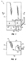
- the reference numeral 10 refers, in general, to a portion of a fluidized bed reactor which includes a furnace section formed by an upright enclosure 12 defined by four walls 12a, 12b, 12c and 12d.
- An air plenum 14 disposed at the lower end portion of the enclosure for receiving air from an external source.
- a furnace grid floor 16 is provided at the interface between the lower end of the enclosure 12 and the air plenum 14 and a plurality of fluidizing nozzles 17 are disposed on the floor 16 for allowing the pressurized air from the plenum to pass upwardly into the enclosure 10 for reasons to be described.
- a bed 18 of particulate material consisting of coal and relatively fine particles of an sorbent material, such as limestone, for collecting the sulfur generated during the combustion of the coal, in a known manner.
- an sorbent material such as limestone
- one or more inlets are provided through a wall of the enclosure for introducing the particulate material onto the bed, and a drain pipe (not shown) can be provided which extends through an opening in the floor 16 for discharging spent particulate material from the bed 18.
- the velocity of air from the plenum 14 passing into the enclosure is controlled so that it fluidizes the particulate material in the bed 18 to form a bubbling or circulating fluidized bed.
- the walls 12a, 12b, 12c and 12d of the enclosure 12 include a plurality of water tubes disposed in a vertically extending relationship and that flow circuitry (not shown) is provided to pass water through the tubes to convert the water to steam. Since the type of construction is conventional, the walls will not be described in any further detail.
- the reactor 10 includes one or more separators provided adjacent the enclosure 12 and connected thereto in a manner to receive the flue gases and entrained particulate material from the fluidized bed 18. Since the separator is conventional and form no part of the present invention it is not shown in the drawing.
- the separator receives the flue gases and entrained particulate material from the fluidized bed 18 in the enclosure 12 and operates in a conventional manner to disengage the particulate material from the flue gases due to the centrifugal forces created in the separator.
- the separated flue gases are then passed into and through a heat recovery area (not shown).
- the separated particles from the separator pass into an inlet nozzle 20 connected to the outlet of the separator.
- a sparger pipe (not shown), or similar air distribution devices, may be disposed in the inlet nozzle 20 to fluidize the solids as required.
- the inlet nozzle 20 extends into and through the lower rear wall portion of the enclosure 12 for discharging the separated particulate material into a sealing section disposed in the enclosure 12 and referred to in general by the reference numeral 22.
- the sealing section 22 is defined by the enclosure wall 12b, three partitions 24, 26 and 28 and a roof 30.
- the partition 24 includes an upper section 24a extending from the floor 16 to a predetermined height in the enclosure 12 and a lower section 24b extending from the floor of the air plenum 14 to the floor 16.
- the partitions 26 and 28 include an upper section and a lower section in a similar manner.
- the partition sections 24a and 24b define a common wall between the furnace section of the reactor 10 and the sealing section 22.
- partitions 24, 26 and 28, including their respective upper and lower sections, as well as the roof 30, may be comprised of refractory, refractory or suitably lined air or water cooled material or combinations thereof, or can be formed by water tubes in the manner described in connection with the walls of the enclosure 12.
- the sealing section 22 also includes an air plenum 14a and a floor 16a which are extensions of the air plenum 14 and the floor 16, respectively, and a plurality of fluidizing nozzles 17a extending above the floor 16a.
- the separated particulate material from the inlet nozzle 20 is introduced to the interior of the sealing section 22 and builds up on the floor 16a to form a bed 32.
- An opening is provided in the upper portion of the partition section 24 to permit the particulate material to pass from the bed 32 to the bed 18 as will be described.
- particulate fuel material and sorbent are introduced into the enclosure 12, as needed.
- Pressurized air from an external source passes into and through the air plenum 14, through the floor 16 and into the bed 18 of particulate material in the enclosure 12 to fluidize the material.
- the velocity of the air introduced, via the air plenum 14, through the floor 16 and into the interior of the enclosure 12 is established in accordance with the size of the particulate material so that either a bubbling or circulating fluidized bed is formed as discussed above.
- a lightoff burner (not shown), or the like, is disposed in the enclosure 12 and is fired to ignite the particulate fuel material.
- additional fuel is discharged into the enclosure 12.
- the material in the enclosure 10 is self-combusted and the mixture of air and gaseous products of combustion (hereinafter referred to as "flue gases") passes upwardly through the enclosure 12 and entrain, or elutriate, the relatively fine particulate material in the enclosure.
- the flue gases, with the entrained particulate material pass to the upper portion of the enclosure 12 and exit into a cyclone separator (not shown). In the separator, the solid particulate material is separated from the flue gases and the former passes into and through the inlet nozzle 20 and into the sealing section 22 to form the bed 32.
- the particulate material from the inlet nozzle 20 builds up in the sealing section 22 until the height of the bed 32 reaches the height of the partition section 24a.
- the material flows through the opening in the upper portion of the partition section 24a and onto the fluidized bed 18 in the furnace section of the reactor 10 where it mixes with the particulate material in the latter bed.
- Air is passed from an opening in the partition 24b or from an external source, into the plenum 14a and through the nozzles 17a, to fluidize the particulate material in the bed 32.
- Water is passed through the walls of the enclosure 12 to exchange heat with the fluidized bed 18 and generate steam.
- the steam then passes through a heat recovery section (not shown) of the reactor before being discharged to external equipment such as a steam turbine.
- the present invention eliminates the use of expensive sealing devices between the cyclone separator solids outlet and the furnace section of the reactor, yet insures against the backflow of gases from the enclosure 12 to the outlet of the separator through inlet nozzle 20.
- the particular location of the sealing section 22 within the reactor 10 can be varied, such as by locating it at any elevation within the reactor.
- the sealing section 22 may transfer solids from the bed 32 to the bed 18 through an outlet nozzle located in the partition sections 24a, 26a, or 28a, the roof 30, or the floor 16a.
- the roof 30 of the sealing section 23 may be eliminated, and, the system for transferring the solids from the bed 32 to the bed 18 can be located totally outside the reactor.
- the sealing section may contain individual isolation zones.
Landscapes
- Chemical & Material Sciences (AREA)
- Engineering & Computer Science (AREA)
- Combustion & Propulsion (AREA)
- Chemical Kinetics & Catalysis (AREA)
- General Engineering & Computer Science (AREA)
- Organic Chemistry (AREA)
- Mechanical Engineering (AREA)
- Fluidized-Bed Combustion And Resonant Combustion (AREA)
- Devices And Processes Conducted In The Presence Of Fluids And Solid Particles (AREA)
- Production Of Liquid Hydrocarbon Mixture For Refining Petroleum (AREA)
- Gasification And Melting Of Waste (AREA)
- Polymerisation Methods In General (AREA)
- Crucibles And Fluidized-Bed Furnaces (AREA)
Applications Claiming Priority (2)
| Application Number | Priority Date | Filing Date | Title |
|---|---|---|---|
| US35358189A | 1989-05-18 | 1989-05-18 | |
| US353581 | 1989-05-18 |
Publications (3)
| Publication Number | Publication Date |
|---|---|
| EP0398718A2 true EP0398718A2 (de) | 1990-11-22 |
| EP0398718A3 EP0398718A3 (de) | 1991-02-06 |
| EP0398718B1 EP0398718B1 (de) | 1993-09-08 |
Family
ID=23389744
Family Applications (1)
| Application Number | Title | Priority Date | Filing Date |
|---|---|---|---|
| EP19900305339 Expired - Lifetime EP0398718B1 (de) | 1989-05-18 | 1990-05-17 | Dichtungssystem für Feststoffrückführung in einem Wirbelbettreaktor |
Country Status (6)
| Country | Link |
|---|---|
| EP (1) | EP0398718B1 (de) |
| JP (1) | JPH0610525B2 (de) |
| CN (1) | CN1024394C (de) |
| CA (1) | CA2016898A1 (de) |
| ES (1) | ES2044437T3 (de) |
| PT (1) | PT94082A (de) |
Families Citing this family (2)
| Publication number | Priority date | Publication date | Assignee | Title |
|---|---|---|---|---|
| KR100577734B1 (ko) * | 2005-01-11 | 2006-05-10 | 박진수 | 두피 자극수단이 구비된 가발 |
| US8494711B2 (en) | 2010-01-04 | 2013-07-23 | GM Global Technology Operations LLC | Automated start-stop systems and methods for internal combustion engines |
Family Cites Families (3)
| Publication number | Priority date | Publication date | Assignee | Title |
|---|---|---|---|---|
| US4469050A (en) * | 1981-12-17 | 1984-09-04 | York-Shipley, Inc. | Fast fluidized bed reactor and method of operating the reactor |
| ATE87077T1 (de) * | 1985-06-12 | 1993-04-15 | Metallgesellschaft Ag | Verbrennungsvorrichtung mit zirkulierender wirbelschicht. |
| US4688521A (en) * | 1986-05-29 | 1987-08-25 | Donlee Technologies Inc. | Two stage circulating fluidized bed reactor and method of operating the reactor |
-
1990
- 1990-05-16 CA CA 2016898 patent/CA2016898A1/en not_active Abandoned
- 1990-05-17 PT PT9408290A patent/PT94082A/pt not_active Application Discontinuation
- 1990-05-17 EP EP19900305339 patent/EP0398718B1/de not_active Expired - Lifetime
- 1990-05-17 ES ES90305339T patent/ES2044437T3/es not_active Expired - Lifetime
- 1990-05-18 CN CN 90103711 patent/CN1024394C/zh not_active Expired - Fee Related
- 1990-05-18 JP JP12706590A patent/JPH0610525B2/ja not_active Expired - Lifetime
Also Published As
| Publication number | Publication date |
|---|---|
| EP0398718B1 (de) | 1993-09-08 |
| PT94082A (pt) | 1991-12-31 |
| EP0398718A3 (de) | 1991-02-06 |
| JPH0610525B2 (ja) | 1994-02-09 |
| ES2044437T3 (es) | 1994-01-01 |
| JPH0339808A (ja) | 1991-02-20 |
| CN1024394C (zh) | 1994-05-04 |
| CA2016898A1 (en) | 1990-11-18 |
| CN1047221A (zh) | 1990-11-28 |
Similar Documents
| Publication | Publication Date | Title |
|---|---|---|
| EP0365723B1 (de) | Wirbelschichtreaktor mit integriertem Rückführungswärmeaustauscher | |
| US5239946A (en) | Fluidized bed reactor system and method having a heat exchanger | |
| US4947804A (en) | Fluidized bed steam generation system and method having an external heat exchanger | |
| US5141708A (en) | Fluidized bed combustion system and method having an integrated recycle heat exchanger | |
| EP0290213B1 (de) | Verfahren und Anlage zur Regelung des Sammelwirkungsgrades des Zyklons und des Rückführungsgrades in Wirbelschichtreaktoren | |
| CA1269900A (en) | Fluidized bed steam generator and method of generating steam with flyash recycle | |
| US5339774A (en) | Fluidized bed steam generation system and method of using recycled flue gases to assist in passing loopseal solids | |
| WO1994011673A1 (en) | Method and apparatus for operating a circulating fluidized bed system | |
| US5269263A (en) | Fluidized bed reactor system and method of operating same | |
| EP0346062B1 (de) | Wirbelbettreaktor mit Spaltabscheider in Form von Rinnen | |
| US5570645A (en) | Fluidized bed system and method of operating same utilizing an external heat exchanger | |
| US4809625A (en) | Method of operating a fluidized bed reactor | |
| EP0592737A1 (de) | Horizontaler Zyklonseparator für einen Wirbelbettreaktor | |
| US5471955A (en) | Fluidized bed combustion system having a heat exchanger in the upper furnace | |
| EP0503917B1 (de) | Wirbelbettreaktor und Verfahren zu ihrem Betrieb unter Anwendung eines Teilchenbeseitigungssystem | |
| US4951611A (en) | Fluidized bed reactor utilizing an internal solids separator | |
| US5242662A (en) | Solids recycle seal system for a fluidized bed reactor | |
| US5372096A (en) | Internal particle collecting cells for circulating fluid bed combustion | |
| GB2178674A (en) | A method of operating a fluidized bed reactor | |
| EP0398718B1 (de) | Dichtungssystem für Feststoffrückführung in einem Wirbelbettreaktor | |
| US5347954A (en) | Fluidized bed combustion system having an improved pressure seal | |
| US5022893A (en) | Fluidized bed steam temperature enhancement system | |
| CA1309898C (en) | Fluidized bed reactor having an integrated recycle heat exchanger | |
| JPH0642941B2 (ja) | 一体型再循環熱交換器を有する流動床反応装置及びその操作方法 |
Legal Events
| Date | Code | Title | Description |
|---|---|---|---|
| PUAI | Public reference made under article 153(3) epc to a published international application that has entered the european phase |
Free format text: ORIGINAL CODE: 0009012 |
|
| AK | Designated contracting states |
Kind code of ref document: A2 Designated state(s): ES GB IT NL |
|
| PUAL | Search report despatched |
Free format text: ORIGINAL CODE: 0009013 |
|
| AK | Designated contracting states |
Kind code of ref document: A3 Designated state(s): ES GB IT NL |
|
| 17P | Request for examination filed |
Effective date: 19910701 |
|
| 17Q | First examination report despatched |
Effective date: 19911220 |
|
| GRAA | (expected) grant |
Free format text: ORIGINAL CODE: 0009210 |
|
| AK | Designated contracting states |
Kind code of ref document: B1 Designated state(s): ES GB IT NL |
|
| ITF | It: translation for a ep patent filed | ||
| REG | Reference to a national code |
Ref country code: ES Ref legal event code: FG2A Ref document number: 2044437 Country of ref document: ES Kind code of ref document: T3 |
|
| PGFP | Annual fee paid to national office [announced via postgrant information from national office to epo] |
Ref country code: NL Payment date: 19940531 Year of fee payment: 5 |
|
| PGFP | Annual fee paid to national office [announced via postgrant information from national office to epo] |
Ref country code: GB Payment date: 19940606 Year of fee payment: 5 |
|
| PGFP | Annual fee paid to national office [announced via postgrant information from national office to epo] |
Ref country code: ES Payment date: 19940627 Year of fee payment: 5 |
|
| PLBE | No opposition filed within time limit |
Free format text: ORIGINAL CODE: 0009261 |
|
| STAA | Information on the status of an ep patent application or granted ep patent |
Free format text: STATUS: NO OPPOSITION FILED WITHIN TIME LIMIT |
|
| 26N | No opposition filed | ||
| PG25 | Lapsed in a contracting state [announced via postgrant information from national office to epo] |
Ref country code: GB Effective date: 19950517 |
|
| PG25 | Lapsed in a contracting state [announced via postgrant information from national office to epo] |
Ref country code: ES Free format text: LAPSE BECAUSE OF NON-PAYMENT OF DUE FEES Effective date: 19950518 |
|
| PG25 | Lapsed in a contracting state [announced via postgrant information from national office to epo] |
Ref country code: NL Effective date: 19951201 |
|
| GBPC | Gb: european patent ceased through non-payment of renewal fee |
Effective date: 19950517 |
|
| NLV4 | Nl: lapsed or anulled due to non-payment of the annual fee |
Effective date: 19951201 |
|
| REG | Reference to a national code |
Ref country code: ES Ref legal event code: FD2A Effective date: 19990405 |
|
| PG25 | Lapsed in a contracting state [announced via postgrant information from national office to epo] |
Ref country code: IT Free format text: LAPSE BECAUSE OF NON-PAYMENT OF DUE FEES;WARNING: LAPSES OF ITALIAN PATENTS WITH EFFECTIVE DATE BEFORE 2007 MAY HAVE OCCURRED AT ANY TIME BEFORE 2007. THE CORRECT EFFECTIVE DATE MAY BE DIFFERENT FROM THE ONE RECORDED. Effective date: 20050517 |