EP0399006B1 - Zentralverwaltungssystem der bewässerungseinheiten - Google Patents
Zentralverwaltungssystem der bewässerungseinheiten Download PDFInfo
- Publication number
- EP0399006B1 EP0399006B1 EP89911643A EP89911643A EP0399006B1 EP 0399006 B1 EP0399006 B1 EP 0399006B1 EP 89911643 A EP89911643 A EP 89911643A EP 89911643 A EP89911643 A EP 89911643A EP 0399006 B1 EP0399006 B1 EP 0399006B1
- Authority
- EP
- European Patent Office
- Prior art keywords
- irrigation
- controller
- memory device
- control
- irrigation controller
- Prior art date
- Legal status (The legal status is an assumption and is not a legal conclusion. Google has not performed a legal analysis and makes no representation as to the accuracy of the status listed.)
- Expired - Lifetime
Links
Images


Classifications
-
- G—PHYSICS
- G06—COMPUTING OR CALCULATING; COUNTING
- G06F—ELECTRIC DIGITAL DATA PROCESSING
- G06F8/00—Arrangements for software engineering
- G06F8/60—Software deployment
- G06F8/61—Installation
-
- A—HUMAN NECESSITIES
- A01—AGRICULTURE; FORESTRY; ANIMAL HUSBANDRY; HUNTING; TRAPPING; FISHING
- A01G—HORTICULTURE; CULTIVATION OF VEGETABLES, FLOWERS, RICE, FRUIT, VINES, HOPS OR SEAWEED; FORESTRY; WATERING
- A01G25/00—Watering gardens, fields, sports grounds or the like
- A01G25/16—Control of watering
-
- G—PHYSICS
- G05—CONTROLLING; REGULATING
- G05B—CONTROL OR REGULATING SYSTEMS IN GENERAL; FUNCTIONAL ELEMENTS OF SUCH SYSTEMS; MONITORING OR TESTING ARRANGEMENTS FOR SUCH SYSTEMS OR ELEMENTS
- G05B19/00—Program-control systems
- G05B19/02—Program-control systems electric
- G05B19/04—Program control other than numerical control, i.e. in sequence controllers or logic controllers
- G05B19/042—Program control other than numerical control, i.e. in sequence controllers or logic controllers using digital processors
- G05B19/0426—Programming the control sequence
-
- G—PHYSICS
- G05—CONTROLLING; REGULATING
- G05B—CONTROL OR REGULATING SYSTEMS IN GENERAL; FUNCTIONAL ELEMENTS OF SUCH SYSTEMS; MONITORING OR TESTING ARRANGEMENTS FOR SUCH SYSTEMS OR ELEMENTS
- G05B2219/00—Program-control systems
- G05B2219/20—Pc systems
- G05B2219/23—Pc programming
- G05B2219/23051—Remote control, enter program remote, detachable programmer
-
- G—PHYSICS
- G05—CONTROLLING; REGULATING
- G05B—CONTROL OR REGULATING SYSTEMS IN GENERAL; FUNCTIONAL ELEMENTS OF SUCH SYSTEMS; MONITORING OR TESTING ARRANGEMENTS FOR SUCH SYSTEMS OR ELEMENTS
- G05B2219/00—Program-control systems
- G05B2219/20—Pc systems
- G05B2219/23—Pc programming
- G05B2219/23297—Remote load of program with cellular, wireless, satellite connection
-
- G—PHYSICS
- G05—CONTROLLING; REGULATING
- G05B—CONTROL OR REGULATING SYSTEMS IN GENERAL; FUNCTIONAL ELEMENTS OF SUCH SYSTEMS; MONITORING OR TESTING ARRANGEMENTS FOR SUCH SYSTEMS OR ELEMENTS
- G05B2219/00—Program-control systems
- G05B2219/20—Pc systems
- G05B2219/23—Pc programming
- G05B2219/23425—Selection of program, adaptive to process
-
- G—PHYSICS
- G05—CONTROLLING; REGULATING
- G05B—CONTROL OR REGULATING SYSTEMS IN GENERAL; FUNCTIONAL ELEMENTS OF SUCH SYSTEMS; MONITORING OR TESTING ARRANGEMENTS FOR SUCH SYSTEMS OR ELEMENTS
- G05B2219/00—Program-control systems
- G05B2219/20—Pc systems
- G05B2219/24—Pc safety
- G05B2219/24069—Diagnostic
-
- G—PHYSICS
- G05—CONTROLLING; REGULATING
- G05B—CONTROL OR REGULATING SYSTEMS IN GENERAL; FUNCTIONAL ELEMENTS OF SUCH SYSTEMS; MONITORING OR TESTING ARRANGEMENTS FOR SUCH SYSTEMS OR ELEMENTS
- G05B2219/00—Program-control systems
- G05B2219/20—Pc systems
- G05B2219/25—Pc structure of the system
- G05B2219/25286—Switch on power, awake controlled machine from standby if command signal
-
- G—PHYSICS
- G05—CONTROLLING; REGULATING
- G05B—CONTROL OR REGULATING SYSTEMS IN GENERAL; FUNCTIONAL ELEMENTS OF SUCH SYSTEMS; MONITORING OR TESTING ARRANGEMENTS FOR SUCH SYSTEMS OR ELEMENTS
- G05B2219/00—Program-control systems
- G05B2219/20—Pc systems
- G05B2219/25—Pc structure of the system
- G05B2219/25289—Energy saving, brown out, standby, sleep, powerdown modus for microcomputer
-
- G—PHYSICS
- G05—CONTROLLING; REGULATING
- G05B—CONTROL OR REGULATING SYSTEMS IN GENERAL; FUNCTIONAL ELEMENTS OF SUCH SYSTEMS; MONITORING OR TESTING ARRANGEMENTS FOR SUCH SYSTEMS OR ELEMENTS
- G05B2219/00—Program-control systems
- G05B2219/20—Pc systems
- G05B2219/25—Pc structure of the system
- G05B2219/25366—Detect code, kind connected machine, device before execution of program
-
- G—PHYSICS
- G05—CONTROLLING; REGULATING
- G05B—CONTROL OR REGULATING SYSTEMS IN GENERAL; FUNCTIONAL ELEMENTS OF SUCH SYSTEMS; MONITORING OR TESTING ARRANGEMENTS FOR SUCH SYSTEMS OR ELEMENTS
- G05B2219/00—Program-control systems
- G05B2219/20—Pc systems
- G05B2219/26—Pc applications
- G05B2219/2625—Sprinkler, irrigation, watering
Definitions
- the present invention concerns the coordinated programming and test control of multiple independent, but irrigation-function interrelated, programmable electronic irrigation controllers within an irrigation system.
- Each irrigation controller controls a number of valves that gate the flow of irrigation water, typically to eight valves per controller. Because each irrigation controller must be electrically wired to all valves that it controls, it is infeasible to have the many hundreds or thousands of valves in a large area irrigation system controlled by a single controller.
- each irrigation controller is independent in its operation, the irrigation control exercised by multiple irrigation controllers is typically interrelated, and must be coordinated. This is because the piping of irrigation water to the stations, or valves, of a number of irrigation controllers is usually in series, one station to the next.
- a fundamental rule of irrigation control is that only such numbers of irrigation stations should be simultaneously enabled for irrigation watering as do not, resultant to the drop on hydrostatic pressure and flow caused by each "on" station, adversely affect irrigation watering pressures, flows, and patterns at any one(s) of the simultaneously enabled stations. Because most irrigation piping is of minimal diameter and cost consonant with the water flow and pressure requirements of a single irrigation station, application of the rule normally requires that only one irrigation station should be enabled any one time.
- Enabling one only irrigation station, or valve, to be on at one time among all the valves controlled by a single irrigation controller is merely a matter of the setup, or programming, of that one irrigation controller.
- a programmer/user of interrelated irrigation controllers must understand the hydrodynamic relationships of the valves controlled by each. These relationships may be several and may be at several hydrodynamic levels within a large irrigation system. In accordance with this understanding, the programmer/user must program irrigation at each irrigation controller in consideration of his/her programming of the other irrigation controllers.
- irrigation controllers themselves are typically difficult and time consuming to program. They are required to be programmed where located, meaning in the field. The weather conditions under which the irrigation controllers must be programmed, and the caliber and diligence of the workers that must tend to the programming, are not always good. Considerable difficulty of coordination between irrigation controllers is experienced. It is hard to affect any appreciable change at any one controller until all controllers are reasonably well coordinated.
- a watering control system comprising a basic unit which is adapted to control a plurality of output control devices such as irrigation valves.
- the basic unit includes a module which is separately removable from the basic unit.
- the module may be moved to and connected with a computer for reprogramming the module from time to time so as to provide for different control periods.
- the irrigation controller comprises a microprocessor which is connected to a non-volatile memory. If necessary, the memory may be reprogrammed electrically.
- US-A-4 648 066 discloses a portable memory module for transferring configuration data from one programmable panel controller to another.
- the present invention contemplates (i) generating one or more programs for one or more potentially interrelated irrigation controllers at a central computer, (ii) downloading the one or more programs from the central computer into a transportable memory device, (iii) transporting, and communicatively connecting, the transportable memory device to each one of the one or more potentially interrelated irrigation controllers in series, and (iv) uploading a program from the transportable memory device into each one of the one or more irrigation controllers.
- the central program generation preferably transpires on a digital computer, typically on a personal computer.
- the computer permits the assembly (or compilation) of the programs that will be executed by the actual irrigation controllers.
- Each irrigation controller preferably contains a microprocessor, nominally a type 6502 contained within an Application Specific Integrated Circuit, and executes firmware programs to effect irrigation control.
- the personal computer generates these firmware programs by running commercially available assemblers (or compilers) for this popular microprocessor. These programs are individualized as required or desired to each irrigation controller.
- the personal computer is preferably programmed so as to emulate the irrigation controllers both individually and collectively.
- This emulation is particularly of the manual input control and, in the form a display, the valve control and/or displays that would be produced by an actual irrigation controller as it would execute a particular actual program.
- the personal computer does not produce control signals to valves during its emulation of an irrigation controller, although it could do so. It is sufficient for the purposes of the present invention that the personal computer should merely emulate the responses of an irrigation controller as it executes a particular program.
- each irrigation controller is entirely controlled by only four pushbutton switches (OK/YES, NO, HELP, and STOP), because each controller generates only a modest number of relatively short messages and the on/off control of only eight valves, and because each controller runs firmware that is easily emulated in execution by the personal computer meanwhile that the controller's emulation need not be (and is usually not) conducted in real time, the emulation of one or more irrigation controllers by the personal computer is straightforward. This simultaneous emulation of one or more controllers permits debug of the control program of any one controller and, importantly, visibility (on the screen of the personal computer's monitor) of the diurnal irrigation control arising from multiple interrelated controllers. A central programmer's task in coordinating a number of interrelated irrigation controllers for the control of irrigation within a single irrigation system is thus much facilitated.
- the transportable memory device preferably interfaces to the personal computer by a standard digital serial interface type RS-232C, and to each irrigation controller by a custom digital interface.
- the custom digital interface is functionally distinguished by starting automatically upon physical electrical connection of the memory device and an irrigation controller, by having the controller automatically identify itself to the memory device and vice versa, and by automatically uploading the appropriate program from the memory device into each individual controller.
- the memory device can preferably carry up to sixty-four (64) complete irrigation control programs simultaneously. It preferably employs the same microprocessor (type 6502 contained within an Application Specific Integrated Circuit) that is also used within the irrigation controller.
- the automated, microprocessor-managed, interchange of unit identities and the automated transfer of an appropriate program minimizes any required human involvement and/or skills at the controllers' field sites, and permits the complex programmed setup of many irrigation controllers to be quickly and easily accomplished by unskilled field workers.
- the irrigation controllers each keep a time-of-day clock. Each controls the conduct of irrigation in accordance with schedules computed by its microprocessor from execution of its individually associated firmware program. Because the programs that were generated at the central source are coordinated for the timed control of irrigation at many dozens or hundreds of stations (valves) within an irrigation system, the actual timed irrigation control effected by the irrigation controllers is also so coordinated. In particular, a number of physically separate and independent irrigation controllers that are interrelated in their required functional control of irrigation may readily be coordinated so as to respond as a single virtual controller. For example, three irrigation controllers controlling eight stations each may readily be coordinated in operation to act as one virtual controller controlling twenty-four stations. The concept of virtual irrigation controllers -- which virtual controllers are readily created and programmed at the personal computer -- much facilitates the ease with which a programmer may think about the programming of coordinated irrigation control within an irrigation system.
- the present invention further contemplates that the irrigation controllers should load information into the portable memory device, and that this information should be carried back to the central station personal computer to be offloaded for analysis, verification, and/or printout.
- the loaded information commonly comprises both the existing, previous, firmware program to that one being uploaded (if any is) plus data in the form of actual historic operational occurrences (normally for the prior 30 days).
- Ability to recover the existing irrigation controller firmware program permits the study and analysis of programs installed in the field, or the verification whether or not programs previously believed to have been installed were so installed in fact.
- the ability to recover actual historical data permits analysis of irregular occurrences, improvement of irrigation watering amounts and schedules in accordance with actual site conditions (especially as sensed by optional moisture sensors), and validation of proper irrigation system performance.
- the present invention still further contemplates that other devices than the transportable memory device should be selectively connectable to the custom digital interface of the irrigation controller.
- Each device identifies itself to the irrigation controller and to its microprocessor operating under firmware program control.
- the irrigation controller thus normally requires no manual intervention other than physical connection of each device in order to cooperatively interoperate with such device.
- a portable maintenance panel extender device connects a substitutionary or additional maintenance panel for that maintenance panel that is customarily under a cover plate of the irrigation controller.
- One benefit so derived is the capability of placing the irrigation controller, which is light-energized, upon a high pole where it is substantially immune from vandalism while maintaining the connection for this portable extended maintenance panel, normally within a strong locked enclosure, at a height whereat it may be conveniently accessed.
- a radio-linked central programming system for multiple irrigation controllers uses a radio transceiver that is connected to each controller's digital interface port.
- a central, or mobile radio transceiver sends and receives controller specific information at prescheduled times, typically diurnally.
- the irrigation controller typically does not have much stored energy to power its connected radio transceiver.
- the radio transceiver is correspondingly inactive at all times save for prescheduled time intervals when an individual controller may be addressed.
- a wireless remote test command system permits manual test operation of the valves connected to an irrigation controller.
- the valves that are connected to an irrigation controller may generally be locally exercised through the maintenance panel of the irrigation controller.
- a self-powered transceiver is temporarily plugged into the digital interface of the irrigation controller.
- a hand-held transceiver that is carried by an installer or maintenance person is used to test the operation of valves (and the readings of optional soil sensors, if implemented) without the necessity of physically returning to the controller. Considerable time and walking may be saved in testing for sprinkler and pipe performance, for leaks or obstructions, in checking soil sensor performance, and in validating all repairs.
- the present invention is embodied in a system for the programming and test control of an irrigation controller.
- the irrigation controller is preferably light-energized for the control of irrigation through eight stations, or valves, of up to 128 total cycles per day.
- the irrigation controller is spoken of as being “light-energized” and (along with the irrigation valves that it controls) to embody "Light-Energized Irrigation Technology” (LEIT).
- LEIT Light-Energized Irrigation Technology
- This description is in lieu of describing, for example, the controller to be “solar powered” because it employs an extremely small area light (solar) collector. Resultant to the small energy collected, the controller uses extremely little energy for all irrigation functions, including control of up to eight (8) valves.
- the acronym LEIT when applied to irrigation controllers is a trademark of Solatrol, Inc. (assignee of the present invention), i.e., LEITTM Irrigation Controllers.
- Light energy required is 0.4 milliwatts/sq cm incident light for a minimum of 7 hrs/day. This is approximately equivalent to one tenth of the amount of light at 55° northern latitude (e.g., in Canada) on a cloudy winter's day.
- the power for the controller's display (when actuated) is derived from a POWERKEYTM (trademark of Solatrol, Inc.) power source.
- the POWERKEYTM power source packages a 9-volt alkaline battery that is used to energize the Liquid Crystal Display (LCD) of the controller during installation and programming.
- LCD Liquid Crystal Display
- the signal output of the controller to its controlled valves is 3.5 volts DC, 0.04 amps for .04 seconds. No circuit breaker and no transformer are required.
- Up to 8 valves may be connected to each controller. Up to 8 electronic soil moisture sensors or optionally, other compatible electronic sensing devices, may also be connected to each controller.
- a user-defined emergency backup program and critical system parameters are stored in non-volative memory in case of memory loss from prolonged light interruption; no batteries are needed.
- LEIT Irrigation controller in accordance with the present invention interfaces with other devices for the loading of irrigation control programs and the manual exercise of irrigation valves and sensors.
- a POWERKEYTM (trademark of Solatrol, Inc.) power source is a combination keyring and keyfob-cased battery for powering the irrigation controller and its display during programming and/or interactive operation.
- the POWERKEYTM power source is manually plugged to the controller. It provides power to the controller for its very first use, and thereafter during each episode of the programming/parameterization of the controller's operation and/or the reviewing of data in the controller's memory.
- the POWERKEYTM power source also provides power to the built-in illumination of the controller's display and control switches.
- the power source that is used during operation of the controller to control irrigation may be the POWERKEYTM power source if it is still pluggably attached (an abnormal condition), but is normally light (even extremely dim light, such as moonlight) that falls upon the controller.
- a MultiprogrammerTM unit plugs into the digital interface of the controller for uploading and downloading the irrigation watering program that is executed by the controller.
- the Multiprogrammer unit simultaneously holds the programs for up to 64 controllers.
- a remote test command assembly mounts in position as a replacement controller face-plate. It plugs into the digital interface of the controller and receives signals from a hand-held transceiver carried by a maintainer in order to allow wireless remote "manual" operation of the controllers valves and sensors. This remote operation characteristically occurs while the maintainer inspects the valve or sensor locations.
- An extension maintenance panel substitutes for, or replicates (as is specified and configured during build of the irrigation controller) the normal maintenance and control panel of the irrigation controller.
- the extension maintenance panel is remotely situated from the controller in a position where it may be accessed.
- the controller is typically located atop a high pole so as to collect light while being isolated from damage due to accident or vandalism.
- the extension maintenance and control panel contains only four switches and a display. It interfaces to the controller's digital interface.
- a radio-link module mounts permanently to the controller at its digital interface.
- the module acts as a transceiver for wireless communication between the controller and a radio-link central system.
- the same program and data information is normally communicated by radio as is alternatively carried in the Multiprogrammer unit.
- Only one of the Multiprogrammer unit, the remote test command assembly, or the radio-link central module attaches to the irrigation controller at its digital interface at one time. Each device identifies itself to the controller, and the individual controller (of which their may be many in an irrigation system) is likewise identified to the device.
- the Multiprogrammer unit, the extension maintenance panel, the radio-link module and the remote test command assembly provide their own power.
- the controller-mounted transceiver of the radio link module is energized but momentarily on a daily schedule. Messages communicated by radio normally include operating programs to be downloaded into the controller, or historical data to be uploaded to the central station. If a message is to be passed, then a controller's radio-link module will remain energized for the duration of the message. Otherwise the powering of the radio link is only momentary.
- Up to 8 optional soil moisture sensor units can connect to the controller to give precise irrigation system control based on readings of available soil moisture tension, or optionally, percentage soil saturation.
- the preferred embodiment of an irrigation controller in accordance with the present invention is light-energized with a built-in incident light collector. It exhibits sufficient energy storage to drive a custom CMOS ultra-low-power microcomputer with 32K RAM memory and to cycle up to eight (8) ultra-low-power irrigation valves up to sixteen (16) times each per twenty-four (24) hour period. This provides complete independence from any need for AC power, saving on energy and installation costs and permitting the controller to be located closer to the valves.
- An on-line help feature gives directions and information for each operational mode and parameter insertion. These on-line help messages are available at any time by pressing a HELP key.
- the design is modular in that multiple 8-valve-station controller units can be integrated together.
- the individual 8-valve-station controller units can be networked together into optionally radio-linked centrally controlled systems, or, alternatively, multiple unrelated controllers on various sites can be centrally managed by optional multi-programming equipment.
- Each of the 8 stations for a single controller unit can be independently programmed within one of six different runtime modes (Mini, Autosplit, Ration, One-Time, and Special. This gives the Irrigation Controller great programming flexibility. Options for (i) simplified “Mini” setups, (ii) "Autosplit” setups with automatically programmed split cycles and sequential non-overlapping operation, (iii) "Ration” setups for odd/even (day of month) water rationing, (iv) "ISC” setups with complete independence between stations, (v) "Special” setup for lights, fountains, and pump-start relays, (vi) periodic or one-time "Add-on Soak Cycle” setups, and (vii) for multiple "Add-on Syringe Cycle” setups are implemented.
- Controller timing control of the irrigation valves is from 1 minute to 240 minutes in one minute increments.
- one minute precision in starting or stopping irrigation is combined with the ability to set watering durations of up to 4 hours for each start time.
- One-time or periodic "soak cycles" can have a duration of up to 8 hours.
- a calendar is maintained based on "perpetual calendar" data in permanent memory. Schedules may be established for specific days or every “so many” days. This permits flexible day cycles for irrigation, and allows different stations to operate on different day cycles.
- the controller's split cycle capability permits watering times to be split into up to 16 substantially equal increments. This minimizes runoff and puddling by splitting the programmed watering duration into shorter cycles each of which is separated by a programmable minimum "off" time.
- a System Budgeting Factor of 10 to 200% acts to determine the numbers of split cycles.
- the System (water) Budgeting Factor increases or decreases the number of split cycles instead of acting as a total duration multiplier which can lead to runoff and puddling.
- Monthly budgeting with preset default values for each month is also available. This allows an entire year's scheduling to be set up.
- An Integrated Moisture Sensor control with programmable "wet” and “dry” trigger levels is optionally implemented for each valve station. This keeps the soil moisture level for each valve within the optimal range for the growth of the type of vegetation being watered by that valve, instead of merely using the optional moisture sensors as switches to override cycle starts.
- Automatic sequential program generation permits "Excluded Time Intervals".
- the controller automatically generates a sequential matrix of start times for all active valves and split irrigation cycles based on user input for determined total watering durations by valve, either site information selection or operator entered number of split cycles, and on any user-defined "Excluded Time Intervals" when no watering is desired.
- the "Special setup” can be used for control of non-valve devices such as pumps, or lighting equipment.
- One-time or periodic "Soak” cycles can be overlaid on any regular watering program. This feature can be used for watering in fertilizer, for periodically deep watering trees and shrubs in turf areas, and for periodically leaching salts in drip applications.
- a programmable “Delay Start” permits watering to be suspended for up to 14 days during rainy weather, and at the end of the programmed "Rain Delay” the regular watering schedule will automatically resume.
- a special "View Info” mode allows the user to review all settings or to view an event report which displays the controller history and current operational setup. This permits the user to easily review the current controller settings or to view a list of the last 128 events (watering cycles, program changes, etc.) in chronological order starting from the earliest event.
- a "Test Sequence” allows each valve to be operated in sequence for one to thirty minutes. This allows the irrigation system to be easily periodically tested.
- a STOP key lets the operator immediately stop the test sequence if broken sprinklers or pipes are found.
- Both valve stations and sensors can be operated automatically, semi-automatically, or manually.
- semi-automatic mode all or selected valves can be run once using the "One-Time” setup. This allows the user to do a one-time soak for watering in fertilizer or new plantings. The controller then automatically reverts to the automatic "Run” mode.
- Three level access codes provide security and render the controller useless if stolen. Separate codes for gardeners, supervisors, and factory personnel insure that only authorized individuals can change the controller settings, and that codes can be easily changed as operating personnel change.
- the preferred embodiment of an irrigation controller in accordance with the present invention uses L ight E nergized I rrigation T echnology (LEITTM). It can operate with the amount of incident light available in northern latitudes on a worst-case cloudy winter's day without needing any of the batteries, external solar panels, or the A.C. power connections required for traditional controllers. It is also extremely flexible and versatile in its operation.
- Controller 1 is typically attached to post 2.
- a photovoltaic device 10 (not shown) is located under transparent lid 11 to case 12.
- a valve connector block 13 permits electrical connection by wires (not shown) to up to eight (8) electromagnetically actuated valves.
- a control key socket 14 accepts a pluggable POWERKEYTM power source (not shown), being a 9 vdc battery suitably packaged so as to plug into socket 14.
- a digital accessory connector 15 permits communication connection to a Multiprogramming unit (not shown) that may upload and download programs into the controller 1 (among other alternative ways of programming controller 1).
- the connector 15 is a standard type, and may, under firmware control within controller 1, interface to further devices.
- a sensor connector block 16 permits connection of up to eight (8) optional soil moisture sensors or other sensing devices. These soil moisture sensors, and the control proceeding therefrom, are not taught within this specification for being unimportant to the present invention.
- a control panel 20 contains a liquid crystal display (LCD) 21 for showing information, questions, and directives.
- the control panel 20 also contains pushbutton switches 22-25.
- a STOP switch 22 stops the present controller 1 operation and turns off any valves previously turned on.
- a HELP switch 23 causes the controller 1 to display more information and/or instructions, keyed to the current operation or displayed questions, in LCD 21.
- the NO switch 24 and the OK switch 25 are used to answer controller-presented questions about the installation and the parameters of irrigation (e.g., the watering schedule) and to enable selectable readout of controller stored data.
- the controller 1 is controlled in its operation by firmware running on a special Application Specific Integrated Circuit (ASIC) that includes a microprocessor.
- ASIC Application Specific Integrated Circuit
- the explanation of the controller 1 hardware is contained in major sections 3-5 of this specification. This major section 2 deals with the user interface to controller 1, and serves to show its many unique aspects in accordance with the present invention.
- programming used throughout this specification includes actions performed at the operator interface to the controller 1 -- actions normally but not necessarily performed in the field -- by which the controller 1 is parameterized and directed in its programmed operation.
- the firmware itself is, of course, also “programmed”. In some cases the act of "programming" at the operator's panel will alter the flow, as well as the parameters used, within the firmware; thus constituting a form of "programming" at the process control level.
- the word “programming” is used to refer to the total compendium of operator/programmer interface to, and control of, irrigation controller 1. The word includes actions more exactingly thought of as parameterization (typically done in the field), as well as actions more exactingly thought of as coding (typically done in the factory or depot).
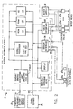
- FIG. 2 A preferred embodiment of an irrigation control system in accordance with the present invention is shown in Figure 2.
- An irrigation controller 1 (previously seen in Figure 1) operates under control of MICROPROCESSOR U2 (partial) executing programmed firmware that is resident in memories types ROM U4, RAM U5, and EE U9.
- the MICROPROCESSOR U2 (partial) communicates with MANUALLY OPERABLE KEYS 22-25 (previously seen in Figure 1) for receipt of data and control. It interfaces with DISPLAY 21 (previously seen in Figure 21) for the display of questions, parameters, and help messages to a human user/programmer (as detailed in previous section 2.0).
- the MICROPROCESSOR U2 (partial) of irrigation controller 1 optionally communicates externally through a SENSOR INTERFACE 26 of plugjack 16 (shown in Figure 1) to up to eight MOISTURE SENSING UNITS (optional) 27a-27h (shown in phantom line). This optional communication is the purpose of sensing soil moisture at up to eight locations.
- the MICROPROCESSOR U2 (partial) communicates through VALVE INTERFACE 28 of plugjack 13 (shown in Figure 1) to up to eight electromagnetically actuated CONTROL VALVES 29a-29h (shown in dashed lines).
- This communication is for the purpose of gating the flow of pressurized water from WATER SUPPLY 30 through a selected one of CONTROL VALVES 29a-29h at any one time to a corresponding one of WATERING HEADS 31a-31h (shown in dashed line).
- the MICROPROCESSOR U2 may optionally communicate through plugjack 15 (shown in Figure 1) to OTHER DEVICES 32 (shown in phantom line) for purposes of receiving the download of firmware programs, parameters, and/or commands.
- This interface need not be enabled to operate the irrigation controller 1, which in a preferred embodiment comes from the factory with that control program that is appendicized to this specification within its ROM memory U4 and EE memory U9, and which in the preferred embodiment may have all necessary parameters and control entered through MANUALLY OPERABLE KEYS 22-25. Indeed, if necessary firmware could be entered into controller 1 through it's MANUALLY OPERABLE KEYS 22-25.
- the digital interface to OTHER DEVICES 32 simply represents a less tedious way of communicating.
- the preferred embodiment of the controller 1 normally derives all its power, and all power for MOISTURE SENSING UNITS 27a-27h and CONTROL VALUES 29a-29h, during quiescent operation both day and night from radiant light energy impinging upon RADIANT ENERGY CONVERTING UNIT (includes ASIC U1) that comprises each of PVM1, U1, and ASSOCIATED CIRCUITRY.
- ASIC U1 includes ASIC U1
- PVM stands for photovoltaic module
- ASIC stands for application specific integrated circuits. All “U” designations stand for integrated circuit chips that may be referenced in Figure 7 (to be discussed).
- controller 1 is powered during its operation to accept user programming not by the RADIANT ENERGY CONVERTING UNIT PVM1, U1, and ASSOCIATED circuitry but rather by electrical connection through plugjack 14 (shown in Figure 1) to the POWERKEYTM PLUGGABLE BATTERY ENERGY SOURCE 33.
- This SOURCE 33 normally not a part of irrigation controller 1 during its quiescent operation, is shown neither in shadow line for being optional, nor in dashed line for being related to the controller 1 of the present invention but not part thereof. Rather, the POWERKEYTM PLUGGABLE BATTERY ENERGY SOURCE is shown in solid line in order to illustrate that for the purposes of programming the controller in accordance with the present invention it must be present.
- the SOURCE 33 supplies the greater power that the MICROPROCESSOR U2 (partial) needs to exit the predominantly somnolent (inactive) state that it only intermittently and momentarily leaves to effect irrigation control in accordance with the schedules, and to assume a high duty cycle at operation.
- the SOURCE 33 also supplies the power requirements of MANUALLY OPERABLE KEYS 22-25 and of DISPLAY 21 during user programming.
- the energy storage within the RADIANT ENERGY CONVERTING UNIT might suffice to permit user programming, it is unwise to deplete this energy storage to an undetermined amount (dependent on the length and adeptness of user programming) -- especially at night when no energy recovery is possible and especially when the controller is programmed to immediately begin controlling irrigation cycles. Instead, the SOURCE 33 actually charges the energy storage means within the RADIANT ENERGY CONVERTING UNIT, and always leaves the controller 1 fully powered and ready to control irrigation of the end of a user programming sequence.
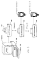
- a MULTIPROGRAMMER unit 300 is carried by a maintenance person 310. It contains all the programming instructions for up to 64 controllers. The MULTIPROGRAMMER unit 300 plugs into one of the IRRIGATION CONTROLLERs 1 through N whereupon the controller identifies itself to the MULTIPROGRAMMER unit and receives any new programming instructions intended uniquely for that controller. During the same communication episode the MULTIPROGRAMMER unit 300 receives and stores existing programs and history data from the controller. Later, back at the maintenance office, the MULTIPROGRAMMER unit 300 plugs into any personal computer PC 320 and reads out this information for verification and/or printout.
- the PC 320 runs software used for programming the IRRIGATION CONTROLLERs, and for emulating their function.
- the preferred software is the "6502 ASSEMBLER" for the 6502 microprocessor chip available from 2500AD Software, Inc., 17200 E. Ohio Drive, Aurora, Colorado 80017.
- the PC 320 may optionally emulate an IRRIGATION CONTROLLER, at least to the extent of accepting the same input control as an actual CONTROLLER and producing an output display that shows a display that would be upon an actual CONTROLLER's maintenance panel.
- the emulation further shows the valve actuations of the CONTROLLER and the times at which such occur.
- the emulation is based on inputting data from KEYBOARD 330 into the PC 320 and then into appropriate data storage addresses of an actual irrigation control program that is resident within the PC.
- the time-of-day clock memory storage location of the irrigation control program its set.
- the irrigation control program is run under its previously mentioned assembler. Certain memory storage locations that represent results of execution of the irrigation control program, such as the message buffer and/or the valve states, are then inspected.
- Custom graphics support can be provided for large users. In the case of a golf course, this would include course maps to allow the user to point to a subsystem he wants to work on rather than identifying it by code.
- FIG. 4 A pictorial diagram of the extension maintenance panel in operational use is shown in Figure 4.
- An irrigation controller 1 that is normally modified so as to not have a control panel 20 (shown in Figure 1) is mounted at the top of a post 2.
- the post 2 may be ten feet or greater in height so as to protect the irrigation controller from inadvertent or intentional damage.
- a RIBBON cable 40 connection of digital accessory connector 15 is extended interior to the hollow post 2 to JUNCTION BOX 41.
- the JUNCTION BOX 41 typically contains a coiled EXTENSION SERIAL CABLE, normally six feet in length. At the end of this cable an EXTENSION MAINTENANCE PANEL 42 is plugged.
- the EXTENSION MAINTENANCE PANEL 42 replicates the same, or equivalent, display 21 and pushbutton switches 21-25 that are within the control panel 20 (shown in Figure 1).
- the maintainer-user 43 may realize equivalent control and exercise of the irrigation controller 1 through EXTENSION MAINTENANCE PANEL 42 as is normally realized through control panel 20.
- a pictorial diagram of the radio-link central programming and monitoring system is shown in Figure 5.
- a radio-link module 50 mounts permanently below the controller 1 on the mounting pipe and serves as a transceiver for wireless communication between the controller and the radio-link CENTRAL STATION 51. This radio communication may be direct via path 52 or indirect via paths 53, 54 via a REMOTE RELAY RF UNIT 55.
- the radio-link CENTRAL STATION 51 may be a MASTER or a SATELLITE.
- a MASTER CENTRAL STATION contains a personal computer (PC) 58 that drives a local CENTRAL STATION RF UNIT 56.
- a SATELLITE CENTRAL STATION 51 contains only a CENTRAL STATION RF UNIT 56 that communicates with the PC 58 of another, MASTER, CENTRAL STATION 51 via the RF UNIT 56 of that station and the TELEPHONE LINES 57.
- the TELEPHONE LINES 57 do not, of course, carry an RF signal. They can, however, carry that information which is either received or broadcast.
- RF to telephone conversion is implemented through a modem located in the RF unit.
- a CENTRAL STATION 51 may be MOBILE, and mounted in a vehicle.
- the N irrigation controllers 1 may typically be programmed during drive-bys (insofar as the normal condition of the controller not to be energized is overcome).
- a tuned RF circuit within the controller may be sufficiently energized by strong RF radiation so as to produce a voltage capable of bringing the irrigation controller 1, and its attached radio-link module 50, awake.
- the radio-link CENTRAL STATION connects into same personal computer 58 that sends radio commands to the controller 1 via the radio link and receives information about the performance of the individual controllers and valves, along with data about soil moisture and other environmental parameters.
- the computer stores program information for all the controllers in the system in its memory and can operate the entire system remotely, via an emulated display panel identical to the on-site controllers. Sophisticated screen graphics and printer capabilities may be used to enhance operator convenience.
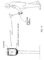
- FIG. 6 A pictorial diagram of a wireless remote test command system is shown in Figure 6.
- the remote test command system permits wireless remote "manual operation" of the valves and soil sensors of irrigation controller 1, in conjunction with an RF Test Adapter 60.
- This transceiver unit 60 is temporarily plugged into the controller 1 and receives "manual mode" commands from the hand-carried test commander 61. It also transmits soil sensor readings back to the hand-carried test commander 61.
- the portable hand-carried test commander 61 units are designed to be moved from controller to controller for installation, testing and maintenance purposes.
- the hand-carried test commander 61 is a hand held transceiver carried by the installer or maintenance person. It is used for remote "manual mode" or test sequence operation of the valves and reading of soil sensors without having to return to the controller. This feature is especially useful in large systems.
- the hand-carried test commander 61 can save the installer/maintenance person considerable time, and miles per day of unnecessary walking, in testing for sprinkler performance, leaks, obstructions, and in checking soil sensor performance.
- the hand-carried test commander 61 will be used for a variety of applications such as activating watering zones only as long as necessary to cleanout the irrigation system, speeding up testing and inspections, and pinpointing cracks in pipe by turning water on briefly from the repair site, without flooding the entire area and for verifying proper operation after repairs are completed.
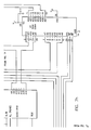
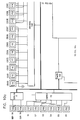
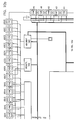
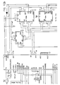
- FIG. 7a The schematic diagram of Figure 7a through Figure 7h, substantially a block diagram because the very substantial function of the circuit shown is contained in two Application Specific Integrated Circuits (ASICs) U1 (shown in Figure 8) and U2 (shown in Figure 10) -- shows the preferred embodiment of irrigation controller 1 (previously seen in Figures 1 and 2) in accordance with the present invention.
- ASICs Application Specific Integrated Circuits
- POWERKEYTM power source is a battery that is connected between terminals BAT + and BAT -.
- the POWERKEYTM power source (not shown) is always connected. Thereby the battery provides the considerable power necessary to energize the display LCD 1, and, importantly, operate the entire controller 1 at the high duty cycle necessary to conduct communications with the operator.
- the battery also serves to initially charge the capacitor power storage (both at a current limited rate) each time the POWERKEYTM battery power source is replugged to its receptacle 14 (shown in Figures 1 and 2). This insures that after each user interface communication the controller is always left in a fully charged condition.
- first ASIC U1 to manage the voltage and power levels of the irrigation controller, and, most particularly, to control the charging of SUPERCAPS C1, C2 by PVM 1 and the POWERKEYTM power source.
- the SUPERCAPS C1, C2 will automatically be charged by connection of the POWERKEYTM power source.
- the ASIC U1 operates to control this charging through a constant current source implemented by transistors Q3, Q4 and resistor R2.
- This constant current source is controlled by a switching regulator implemented from transistor Q2, inductance L1, diode D4, and capacitors C3, C4, all under the control of ASIC U1.
- the switching regulator and constant current source act jointly to pass, during the presence of bright sunshine or of the POWERKEYTM power source, up to 63 milliamperes through steering diode D3 to charge SUPERCAPS C1, C2.
- the diodes D1, D2 prevent discharge of the charged SUPERCAPS C1, C2.
- connections to the ASIC U1 that is used for power management and control include VDD 2.
- VDD 2 is the main +5 vdc power for the irrigation controller 1 and other components (such as CONTROL VALVES 29a-29h or MOISTURE SENSING UNITS 27a-27h both shown in Figure 2) to which it is attached in order to form an irrigation system.
- Signals BA and DX provide local control to the switching regulator and constant current source.
- NSL stands for system low voltage
- NSVL stands for system very low voltage
- NSH1 stands for the first shunt from the upper SUPERCAP
- NSH2 stands for the second shunt from the lower SUPERCAP
- NBP produces a battery present control signal.
- the output PULSE is a real time clock interrupt of 30 microseconds duration occurring each 1/2 millisecond.
- the logical control function of the irrigation controller 1 is substantially implemented by digital ASIC U2, shown extending across each of Figures 7b, 7d, 7f, and 7h.
- the main switch control inputs S1-S6 to ASIC U2, used for operator programming of the irrigation controller 1, are from corresponding switches S1-S6 shown in Figure 7a.
- the switches S1-S6 respectively implement the stop, unused, unused, help, no, and ok switch control inputs to ASIC U2. These switches S1-S6 are called the MANUALLY OPERABLE KEYS 22-25 in Figure 2.
- ASIC U2 offers a total of 16 A/D channels, of which eight are internal and eight are external.
- the irrigation valve control, or drive, signals developed by ASIC U2 are brought to terminal block J2. This terminal block J2 is brought out to plugjack 13 shown in Figures 1 and 2.
- the ASIC U2 operates on firmware instructions, and on parameters, that are stored within both read only memory ROM U4 and in random access memory RAM U5.
- the ASIC U2 addresses both such memories through ADDRESS DECODER U7.
- the irrigation controller 1 is generally versatilely programmable, as well as parameterizable. Thus, many firmware instructions that ASIC U2 executes are present in RAM U5 and are loaded therein in accordance with user requirements. Other firmware instructions reside in ROM U4.
- the irrigation controller 1 in accordance with the present invention connects to still another programmable memory other than RAM U5 (shown in Figure 7h).
- This is Electrically Erasable (EE) 1024 bit serial memory U9.
- EE memory is particularly distinguished in that it will retain its informational contents in the total absence of power (unlike RAM U5). Yet it is alterable in its contents, unlike non-votile ROM U4.
- the 1024 bit serial memory U9 permits the field programming of secret codes, vital set up information, and other information that is desirably user specified (unlike the factory-programmed informational contents of ROM U4), wherein this information will desirably not be lost during any interruption of power to the controller.
- Circuits U6 (save for one unused spare gate shown in Figure 7c), U7, and U8 form a control interface of a standard type from ASIC U2 to the 1024 bit serial EE memory U9.
- address line AD0 powers up
- address line AD1 selects
- address line AD2 clocks serial data present on line AD3 into, 1024 bit memory U9.
- the single, serial, data output bit D0 of 1024 bit memory U9 is amplified in non-inverting element U10 and communicated to ASIC U2 as bit ADO upon its address bus.
- FIG. 8 shows the overall architecture of the first, U1, Application Specific Integrated Circuit (ASIC) used within the preferred embodiment of the irrigation controller in accordance with the present invention.
- ASIC Application Specific Integrated Circuit
- the detail function of ASIC U1 is essentially unimportant for the purposes of the present invention, and is included within this specification only for purposes of completeness.
- the photovoltaic module (PVM, shown in Figure 7a), SUPERCAPS C1 and C2 (shown in Figure 7a) and ASIC U1 (shown in Figure 7a) may be considered to simply be the implementation of a special form of a light-energized power supply.
- the general implementation of an a.c. or battery source power supply is, of course, routine in the electrical arts.
- SUPERCAPS very large supercapacitors
- the U1 ASIC device is designed to use minimal power while providing five (5) functions:
- Sampling capacitors are used to monitor the various capacitor and power supply voltages, allowing the use of only one comparator to conserve current.
- CrSi 100 k ⁇ / resistors are used to minimize analog currents.
- the voltage reference is trimmed using on-chip metal fuses.
- CMOS circuitry There are 3 potential 'most positive' voltages and two potential 'most negative' voltages, making substrate connections difficult. This is handled by using bipolar junction isolation that employs the isolated n- regions as separate CMOS substrates. This allows the CMOS circuitry to operate from several supplies, any one of which could be at the highest potential at different times.
- the logic generally runs from VSS1 (OV) to VDD2 (0-5V), level shifting where required.
- Analog references run from VSS1 to VDD1 (0-11V).
- Switching regulator components run from VSS2 (-.7 to +5.5 V) to VBAT (0 to 15 V).
- the upper shunt transistor is connected to a voltage which can range from 0 to VDD1 +0.7V.
- FIG. 11 A block diagram of the preferred embodiment of the Multiprogrammer usable in the distributed multiple irrigation controller control management system of the present invention is shown in Figure 11.
- Figures 12a through 12c A schematic diagram of the same Multiprogrammer unit is shown in Figures 12, consisting of Figures 12a through 12c.
- the Multiprogrammer unit 300 (previously seen in Figure 3) is based on both the ANALOG ASIC U1 and the DIGITAL ASIC U2 previously seen within the irrigation controller of Figure 7, and respectively individually illustrated in Figures 8 and 10.
- the ANALOG ASIC U1 connects to a BATTERY 70 which may be, but need not be, configured the same as the POWERKEYTM pluggable battery energy source.
- the ANALOG ASIC U1 operates to provide 5 volt dc regulated power to remaining components of the Multiprogrammer unit 300 from the power provided by the BATTERY 70.
- the BATTERY 70 connects through jack J1 terminals 2 and 7 to provide power to the irrigation controller when the multiprogrammer unit 300 is plugged thereto.
- the DIGITAL ASIC U2 containing the microprocessor type 6502, operates on a stored firmware program contained with ROM 71. This program causes the DIGITAL ASIC U2 to communicate through standard universal serial interface UART 72 type 65C51 across an interface I/F type RS232 73. This serial interface connects to a like serial interface port of a computer, particularly the personal computer PC 320 shown in Figure 3.
- the communication path through the RS232 I/F 73 permits the DIGITAL ASIC U2 to receive information that is subsequentially stored within RAM 74.
- the RAM 74 is nominally 512 K by 8 bits in size, and is of type 622S6. At this size it is capable of holding 64 complete programs as are uploaded to those IRRIGATION CONTROLLERs 1 (shown in Figure 3) to which the Multiprogrammer unit 300 at times connects.
- FIG. 12 shows the particular wired interconnection of the functional elements block diagrammed in Figure 11, and more particularly shows the interface between the Multiprogrammer unit 300 and the irrigation controller 1.
- the present invention has been taught in the context of electrical circuits that are fairly sophisticated for employing both a predominantly analog ASIC (ASIC UI) and a predominantly digital ASIC (ASIC U2), it should be understood that the functionality of the preferred embodiment of an irrigation controller in accordance with the present invention is readily realizable by diverse alternative designs.
- the core microprocessor of the preferred embodiment of the invention is 100% compatible with industry standard type 6502. All firmware appended to this specification will execute on a 6502 microprocessor, and is readily convertible to alternative microinstruction repertoires executing on alternative microprocessors.
- the circuits by which data is manually input to the microprocessor and displayed, and the control of irrigation valves, are, in the preferred embodiment of the invention, powered and sequenced to states of activity in a highly unique manner.
Landscapes
- Engineering & Computer Science (AREA)
- Software Systems (AREA)
- General Engineering & Computer Science (AREA)
- Physics & Mathematics (AREA)
- General Physics & Mathematics (AREA)
- Theoretical Computer Science (AREA)
- Automation & Control Theory (AREA)
- Water Supply & Treatment (AREA)
- Life Sciences & Earth Sciences (AREA)
- Environmental Sciences (AREA)
- Stored Programmes (AREA)
- Prostheses (AREA)
- Selective Calling Equipment (AREA)
Claims (10)
- Verfahren zum Programmieren einer Anzahl von physisch verteilten Bewässerungssteuereinheiten (1), die jeweils eine zugehörige Anzahl von Bewässerungsventilen (29a-29h) steuern und die in ihren Betriebseigenschaften der Bewässerungsfunktion innerhalb eines Bewässerungssystems miteinander in Beziehung stehen, wobei das Verfahren umfaßt
das Erzeugen eines Bewässerungshauptplanes unter Berücksichtigung einer Vielzahl von Bewässerungssteuerventilen, die zusammen durch eine physisch verteilte Anzahl von Bewässerungssteuereinheiten (1) steuerbar sind, um die Bewässerung im ganzen Bewässerungssystem insgesamt zu steuern, wobei das Erzeugen Off-Line in einem Computer (320) erfolgt und nicht in der einzelnen Bewässerungssteuereinheit (1), die ein Programm ausführt, das ihr individuell zugeordnet ist, um eine Anzahl von Bewässerungsventilen (29a-29h) zu steuern, die damit verbunden sind, um die Bewässerung zu bewirken;
das Erstellen im Computer (320), aus dem erzeugten Bewässerungshauptplan und unter Berücksichtigung der Anzahl von Bewässerungsventilen, die jeder aus der Anzahl von Bewässerungssteuereinheiten (1) zugeordnet sind und davon gesteuert werden, einer Anzahl von Bewässerungssteuerprogrammen, die jeweils individuell von der zugeordneten einen aus der entsprechenden Anzahl von Bewässerungssteuereinheiten (1) ausgeführt werden können, um im gesamten Bewässerungssystem eine koordinierte Bewässerung zu bewirken;
das Herunterladen der Anzahl von Bewässerungssteuerprogrammen aus dem Computer (320) in eine transportable Speichervorrichtung (300), die in der Lage ist, die Anzahl der Programme aufzunehmen;
das Transportieren der transportablen Speichervorrichtung (300) zu einer der Bewässerungssteuereinheiten (1);
das kommunikative Verbinden der transportablen Speichervorrichtung (300) mit der Bewässerungssteuereinheit (1) durch eine Übertragungsverbindung (15);
das Erkennen, an der transportablen Speichervorrichtung (300) über die Übertragungsverbindung (15), der Identität der einen Bewässerungssteuereinheit (1), die gerade daran angeschlossen ist;
das Hinaufladen des entsprechenden einen aus der Anzahl von Programmen aus der transportablen Speichervorrichtung (300) in die Bewässerungssteuereinheit (1) über die Übertragungsverbindung (15);
das kommunikative Trennen der transportablen Speichervorrichtung (300) von der Bewässerungssteuereinheit (1), wobei die Bewässerungssteuereinheit (1) mit dem entsprechenden einen aus der Anzahl der Bewässerungsprogramme programmiert bleibt; und
das Wiederholen des Transportierens, des kommunikativen Verbindens, des Erkennens, des Hinaufladens und des kommunikativen Trennens, bis jedes aus der Anzahl der Bewässerungsprogramme in die entsprechende eine aus der Anzahl der Bewässerungssteuereinheiten (1) geladen ist;
wobei daraufhin jedes aus der Anzahl der Bewässerungsprogramme in und von der entsprechenden einen aus der Anzahl der Bewässerungssteuereinheiten (1) ausgeführt wird, in die es hinaufgeladen wurde, um eine Steuerung der Bewässerung zu bewirken, die, obwohl sie physisch verteilt ist, sowohl koordiniert als auch in der Tat von einem einzigen Hauptplan abgeleitet ist. - Verfahren nach Anspruch 1, wobei das Hinaufladen von jedem aus der Anzahl der Bewässerungsprogramme in die entsprechende eine aus der Anzahl der Bewässerungssteuereinheiten (1) automatisch erfolgt und ohne menschliches Eingreifen außer bei der Herstellung der kommunikativen Verbindung.
- Verfahren nach Anspruch 1, das, während wenigstens eine aus der Anzahl der Bewässerungssteuereinheiten (1) kommunikativ mit der transportablen Speichervorrichtung (300) verbunden ist, des weiteren umfaßt
das Laden von Informationen aus der kommunikativ angeschlossenen Bewässerungssteuereinheit (1) in die transportable Speichervorrichtung (300). - Verfahren nach Anspruch 3, wobei historische Daten über die Bewässerungssteuerung geladen werden, die von der jeweiligen Bewässerungssteuereinheit (1) bewirkt wurde, die kommunikativ angeschlossen ist.
- Verfahren nach Anspruch 3, wobei das Programm geladen wird, das sich vor dem Hinaufladen in der kommunikativ angeschlossenen Bewässerungssteuereinheit (1) befunden hat.
- Verfahren nach Anspruch 1, wobei die Off-Line-Erzeugung in einem Computersystem (320) erfolgt, das eine echte Bewässerungssteuereinheit emuliert.
- Verfahren nach Anspruch 1, wobei das Herunterladen des erzeugten Programms in den Speicher (74) einer transportablen Speichervorrichtung (300) mit einem Speicher erfolgt; und wobei das Hinaufladen des Programms aus dem Speicher (74) der transportablen Speichervorrichtung (300) erfolgt.
- Verfahren nach Anspruch 1, das, während die Bewässerungssteuereinheit (1) kommunikativ mit der transportablen Speichervorrichtung (300) verbunden ist, des weiteren umfaßt
das Anschließen einer Energiequelle in der transportablen Speichervorrichtung (300) an die Bewässerungssteuereinheit (1) durch einen Energieübertragungsanschluß (14); und
das Zuführen von Energie aus der transportablen Speichervorrichtung (300) zu der Bewässerungssteuereinheit (1) über den Energieübertragungsanschluß (14) zum Hinaufladen des Programms zu der Bewässerungssteuereinheit. - Verfahren nach Anspruch 1, das, zu Zeiten, wenn die transportable Speichervorrichtung (300) nicht kommunikativ an die Bewässerungssteuereinheit (1) angeschlossen ist, des weiteren umfaßt
das Anschließen einer anderen Vorrichtung (42; 50; 51; 60, 61), die zur Betätigung der Steuereinheit geeignet ist, an den physikalisch gleichen Anschluß (15) der Bewässerungssteuereinheit (1), der sonst und zu einer anderen Zeit für die kommunikative Verbindung mit der transportablen Speichervorrichtung verwendet wird; und
das Betreiben der Bewässerungssteuereinheit über die angeschlossene Steuereinheitbetätigungsvorrichtung. - Verfahren nach Anspruch 9, wobei das Betreiben umfaßt
das Veranlassen der Bewässerungssteuereinheit (1), ein Bewässerungsventil (29a...29h) einzuschalten, das an die Bewässerungssteuereinheit angeschlossen ist und davon gesteuert wird.
Applications Claiming Priority (3)
| Application Number | Priority Date | Filing Date | Title |
|---|---|---|---|
| US25515088A | 1988-10-04 | 1988-10-04 | |
| US255150 | 1988-10-04 | ||
| PCT/US1989/004403 WO1990003724A1 (en) | 1988-10-04 | 1989-10-04 | Distributed multiple irrigation controller management system |
Publications (3)
| Publication Number | Publication Date |
|---|---|
| EP0399006A1 EP0399006A1 (de) | 1990-11-28 |
| EP0399006A4 EP0399006A4 (en) | 1991-07-24 |
| EP0399006B1 true EP0399006B1 (de) | 1995-01-04 |
Family
ID=22967050
Family Applications (1)
| Application Number | Title | Priority Date | Filing Date |
|---|---|---|---|
| EP89911643A Expired - Lifetime EP0399006B1 (de) | 1988-10-04 | 1989-10-04 | Zentralverwaltungssystem der bewässerungseinheiten |
Country Status (8)
| Country | Link |
|---|---|
| US (1) | US5173855A (de) |
| EP (1) | EP0399006B1 (de) |
| JP (1) | JPH04500755A (de) |
| AT (1) | ATE116746T1 (de) |
| AU (1) | AU4418389A (de) |
| CA (1) | CA2000139A1 (de) |
| DE (1) | DE68920427T2 (de) |
| WO (1) | WO1990003724A1 (de) |
Cited By (2)
| Publication number | Priority date | Publication date | Assignee | Title |
|---|---|---|---|---|
| ES2187230A1 (es) * | 2000-03-06 | 2003-05-16 | Sistemes Electronics Progres S | Perfeccionamientos en instalaciones de irrigacion y fertilizacion hidroponica o convencional. |
| US20130269798A1 (en) * | 2012-04-11 | 2013-10-17 | Kevin James Wood | Programmable intelligent control method of and system for irrigation system |
Families Citing this family (133)
| Publication number | Priority date | Publication date | Assignee | Title |
|---|---|---|---|---|
| WO1991003156A1 (en) * | 1989-08-28 | 1991-03-21 | Townsend Controls Pty. Ltd. | Irrigation management control |
| FR2665051A1 (fr) * | 1990-07-30 | 1992-01-31 | Sadimato Sa | Installation d'arrosage automatisee. |
| JP2717459B2 (ja) * | 1991-04-24 | 1998-02-18 | ファナック株式会社 | 無線手動操作盤及び無線手動操作盤と数値制御装置との結合方法 |
| IT1249490B (it) * | 1991-06-19 | 1995-02-23 | Nicola Gennaro & Figli Di | Sistema di distribuzione computerizzata dell'acqua in impianti di irrigazione |
| FR2687807B3 (fr) * | 1992-02-21 | 1996-08-14 | Bernard Roux | Programmateur du fonctionnement dans le temps d'un dispositif electrique et installation mettant en óoeuvre ce programmateur. |
| TW272270B (de) * | 1992-08-28 | 1996-03-11 | Compaq Computer Corp | |
| US5540518A (en) * | 1993-09-29 | 1996-07-30 | Linear Dynamics Inc. | Method and apparatus for controlling striping equipment |
| US5699244A (en) * | 1994-03-07 | 1997-12-16 | Monsanto Company | Hand-held GUI PDA with GPS/DGPS receiver for collecting agronomic and GPS position data |
| US5566069A (en) * | 1994-03-07 | 1996-10-15 | Monsanto Company | Computer network for collecting and analyzing agronomic data |
| FR2725005B1 (fr) * | 1994-09-27 | 1997-01-10 | Delattre Sylvain | Dispositif electrique de gestion dans le temps du fonctionnement d'electrovannes |
| US5659705A (en) * | 1994-12-29 | 1997-08-19 | Siemens Energy & Automation, Inc. | Serial access memory cartridge for programmable logic controller |
| US5740031A (en) * | 1995-09-07 | 1998-04-14 | Smart Rain Corp. Inc. | Control system for the irrigation of watering stations |
| US5748466A (en) * | 1995-09-08 | 1998-05-05 | L. R. Nelson | Adaptable control system for a variable number of switches |
| ES2164790T3 (es) * | 1996-01-20 | 2002-03-01 | Thyssen Aufzugswerke Gmbh | Sistema de control remoto y uso de un telefono movil en dicho sistema. |
| IT1282141B1 (it) * | 1996-04-29 | 1998-03-12 | Claber Spa | Centralina di controllo per impianto di irrigazione |
| US6088621A (en) * | 1996-06-21 | 2000-07-11 | Hunter Industries, Inc. | Portable apparatus for rapid re-programming of irrigation controllers |
| US5884224A (en) * | 1997-03-07 | 1999-03-16 | J.R. Simplot Company | Mobile mounted remote sensing/application apparatus for interacting with selected areas of interest within a field |
| US5960813A (en) * | 1997-07-25 | 1999-10-05 | Sturman; Oded E. | Solar powered programmable valve and methods of operation thereof |
| DE19737721A1 (de) * | 1997-08-29 | 1999-03-04 | Gardena Kress & Kastner Gmbh | Vorrichtung zur programmgesteuerten Ausführung einer Funktion |
| US6856654B1 (en) | 1997-09-15 | 2005-02-15 | Research In Motion Limited | Power supply system for a packet-switched radio transmitter |
| US6104759A (en) * | 1997-09-15 | 2000-08-15 | Research In Motion Limited | Power supply system for a packet-switched radio transmitter |
| US9075136B1 (en) | 1998-03-04 | 2015-07-07 | Gtj Ventures, Llc | Vehicle operator and/or occupant information apparatus and method |
| US6453215B1 (en) | 1998-04-14 | 2002-09-17 | Nathan Lavoie | Irrigation controller |
| US6002984A (en) * | 1998-05-04 | 1999-12-14 | Aughenbaugh; Timothy A. | Method and system for enabling use of current information about farming data |
| US6125868A (en) * | 1998-06-18 | 2000-10-03 | Hydra-Stop, Inc. | Method and apparatus for maintaining valves in a water distribution system |
| US6257264B1 (en) | 1999-01-25 | 2001-07-10 | Sturman Bg, Llc | Programmable electronic valve control system and methods of operation thereof |
| AUPQ299399A0 (en) * | 1999-09-22 | 1999-10-14 | Irrigation Control Networks Pty Ltd | Virtual control system and operational method |
| US7068147B2 (en) | 1999-12-07 | 2006-06-27 | Denso Corporation | Control information rewriting system |
| US6600971B1 (en) * | 2000-03-29 | 2003-07-29 | Signature Control Systems, Inc. | Distributed control network for irrigation management |
| US7734287B2 (en) * | 2000-04-10 | 2010-06-08 | I/O Controls Corporation | System for providing remote access to diagnostic information over a wide area network |
| US6847916B1 (en) | 2000-06-12 | 2005-01-25 | I/O Controls Corporation | Method and system for monitoring, controlling, and locating portable devices performing remote diagnostic analysis of control network |
| WO2001077765A1 (en) * | 2000-04-10 | 2001-10-18 | I/O Controls Corporation | Method and system for remote analysis of control network |
| US6757521B1 (en) | 2000-06-12 | 2004-06-29 | I/O Controls Corporation | Method and system for locating and assisting portable devices performing remote diagnostic analysis of a control network |
| US8472942B2 (en) | 2000-06-12 | 2013-06-25 | I/O Controls Corporation | System and method for facilitating diagnosis and maintenance of a mobile conveyance |
| US7315764B1 (en) * | 2000-06-14 | 2008-01-01 | Marvell International Ltd | Integrated circuit, method, and computer program product for recording and reproducing digital data |
| US7457676B1 (en) * | 2000-06-14 | 2008-11-25 | Marvell International Ltd. | Vehicle for recording and reproducing digital data |
| US7546172B1 (en) * | 2000-06-14 | 2009-06-09 | Marvell International Ltd. | Apparatus, method, and computer program product for recording and reproducing digital data |
| US7778736B2 (en) * | 2000-06-14 | 2010-08-17 | Marvell International Ltd. | Apparatus, method, and computer program for sprinkler control |
| DE10032774A1 (de) * | 2000-07-06 | 2002-01-17 | Endress Hauser Gmbh Co | Feldgerät |
| WO2002017540A2 (en) * | 2000-08-22 | 2002-02-28 | Deere & Company | System and method for developing a farm management plan for production agriculture |
| EP1316001B1 (de) * | 2000-09-08 | 2005-06-15 | Brueninghaus Hydromatik Gmbh | Servicesystem für steuergeräte von hydrostatischen antrieben |
| WO2002023300A1 (en) * | 2000-09-13 | 2002-03-21 | Aqua Conservation Systems, Inc. | Irrigation controller stores history and calculates schedule |
| CA2363246C (en) | 2000-11-06 | 2006-02-21 | Blackberry Limited | Portable battery charger |
| CA2374344C (en) * | 2001-03-01 | 2006-02-21 | Research In Motion Limited | Multifunctional charger system and method |
| CA2517333C (en) * | 2001-03-01 | 2007-11-27 | Research In Motion Limited | System and method for powering and charging a mobile communication device |
| FR2822345B1 (fr) * | 2001-03-21 | 2003-08-22 | Atelog Bretagne Pays De Loire | Procede et installation pour la gestion de chauffage et/ou de l'arrosage de tunnels de culture |
| FR2824931B1 (fr) * | 2001-05-16 | 2003-10-10 | Bhl Electronique S A | Dispositif de programmation d'un automate |
| DE20119416U1 (de) * | 2001-11-30 | 2003-04-10 | GSR Ventiltechnik GmbH & Co. KG, 32602 Vlotho | Autarke Pipeline-Armatur |
| US7359769B2 (en) * | 2001-12-20 | 2008-04-15 | Rain Bird Corporation | Wireless irrigation control device and related method |
| US6782310B2 (en) * | 2001-12-20 | 2004-08-24 | Rain Bird Corporation | Wireless irrigation control device and related method |
| ITMI20012790A1 (it) * | 2001-12-21 | 2003-06-21 | Claber Spa | Sistema centralizzato per il controllo remoto di impianti di irrigazione |
| FR2836728B1 (fr) * | 2002-03-04 | 2005-06-24 | Rain Bird Europ Sarl | Nouveau concept de programmateur d'arrosage irrigation dont le programme est inscrit sur un support exterieur |
| FR2838288B1 (fr) * | 2002-03-04 | 2005-11-25 | Rain Bird Europ Sarl | Procede et dispositif de programmation pour une installation d'arrosage ou d'irrigation et une telle installation |
| ES2208058B1 (es) * | 2002-03-11 | 2005-09-16 | Empresa De Transformacion Agraria, S.A. (Tragsa) | Nodo de riego para un sistema integral de gestion por control remoto de redes hidraulicas de riego. |
| US6685104B1 (en) | 2002-07-17 | 2004-02-03 | Ardele Y. Float | Landscape sprinkling systems |
| US7444207B2 (en) | 2002-10-15 | 2008-10-28 | Rain Bird Corporation | Modular and expandable irrigation controller |
| CA2427369A1 (en) * | 2002-12-24 | 2004-06-24 | Research In Motion Limited | Methods and apparatus for controlling power to electrical circuitry of a wireless communication device having a subscriber identity module (sim) interface |
| US6833686B2 (en) * | 2003-02-21 | 2004-12-21 | Research In Motion Limited | Circuit and method of operation for an adaptive charge rate power supply |
| US7791319B2 (en) | 2003-02-21 | 2010-09-07 | Research In Motion Limited | Circuit and method of operation for an electrical power supply |
| US7079970B2 (en) * | 2003-09-04 | 2006-07-18 | Tonerhead, Inc. | Printer tester |
| US7050887B2 (en) * | 2003-12-23 | 2006-05-23 | Techstream Control Systems Inc. | Wireless sensor and control transmitter system |
| MXPA06007327A (es) | 2003-12-23 | 2007-04-10 | Rain Bird Corp | Controlador de irrigacion modular y expansible. |
| US7844367B2 (en) | 2003-12-23 | 2010-11-30 | Rain Bird Corporation | Code replacement for irrigation controllers |
| US7458521B2 (en) | 2004-10-30 | 2008-12-02 | Norman Ivans | Irrigation unit having a control system and a data storage unit |
| US7191955B2 (en) | 2004-12-22 | 2007-03-20 | Norman Ivans | Irrigation unit having a control system that performs a self-test and a cleaner that cleans the unit |
| US7617992B2 (en) | 2004-10-30 | 2009-11-17 | Norman Ivans | System and method for maintaining irrigation accuracy of an irrigation system |
| US7097113B2 (en) | 2004-01-20 | 2006-08-29 | Norman Ivans | Irrigation unit including a power generator |
| US7708206B2 (en) | 2004-12-22 | 2010-05-04 | Norman Ivans | Irrigation unit including a nozzle having greater accuracy and improved adjustment properties |
| US7328089B2 (en) * | 2004-02-11 | 2008-02-05 | The Toro Company | Satellite irrigation controller |
| US7613546B2 (en) * | 2004-08-06 | 2009-11-03 | The Toro Company | Modular irrigation controller |
| US8793024B1 (en) * | 2009-02-27 | 2014-07-29 | Hunter Industries, Inc. | Irrigation system with multiple soil moisture based seasonal watering adjustment |
| US20100094472A1 (en) | 2008-10-14 | 2010-04-15 | Woytowitz Peter J | Irrigation System With Soil Moisture Based Seasonal Watering Adjustment |
| US20100030476A1 (en) * | 2008-07-29 | 2010-02-04 | Woytowitz Peter J | Irrigation System with ET Based Seasonal Watering Adjustment |
| US9301461B2 (en) | 2004-11-09 | 2016-04-05 | Hunter Industries, Inc. | Systems and methods to adjust irrigation |
| FR2878043B1 (fr) * | 2004-11-12 | 2007-03-23 | Briot Internat Sa | Systeme de chargement d'informations dans une machine automatisee de taille d'un verre optique a partir d'une ebauche |
| CA2601061A1 (en) * | 2005-03-11 | 2006-09-21 | Tonerhead, Inc. | Method and apparatus for a printer cartridge tester |
| US7665819B2 (en) * | 2005-04-21 | 2010-02-23 | Tonerhead, Inc. | Method and apparatus for a printer cartridge tester |
| WO2007011999A2 (en) | 2005-07-19 | 2007-01-25 | Rain Bird Corporation | Wireless extension to an irrigation control system and related methods |
| TWI342472B (en) * | 2005-12-01 | 2011-05-21 | Sandisk Corp | System for managing and repairing an appliance, non-volatile memory device, appliance, and method for managing and repairing an appliance |
| US7739078B2 (en) | 2005-12-01 | 2010-06-15 | Sandisk Corporation | System for managing appliances |
| US7353073B2 (en) | 2005-12-01 | 2008-04-01 | Sandisk Corporation | Method for managing appliances |
| US20070260400A1 (en) * | 2006-05-04 | 2007-11-08 | Omry Morag | Computerized crop growing management system and method |
| US8224493B2 (en) * | 2006-05-30 | 2012-07-17 | Rain Bird Corporation | Same code base in irrigation control devices and related methods |
| US8433448B2 (en) * | 2006-05-30 | 2013-04-30 | Rain Bird Corporation | Same code base in irrigation control devices and related methods |
| US7886338B2 (en) * | 2006-10-06 | 2011-02-08 | Control4 Corporation | System and method for controlling access to local services without losing failover capibilty |
| US8107946B2 (en) * | 2007-02-22 | 2012-01-31 | Control4 Corporation | System and method for using a wired network to send response messages in an automation system |
| GB2447241A (en) * | 2007-03-05 | 2008-09-10 | Richard Hoptroff | Memory programming device |
| US8436943B2 (en) * | 2007-03-22 | 2013-05-07 | Control4 Corporation | System and method for automated audio visual system control |
| US20080238668A1 (en) * | 2007-03-28 | 2008-10-02 | Control4 Corporation | System and method for security monitoring between trusted neighbors |
| US20100321151A1 (en) * | 2007-04-04 | 2010-12-23 | Control4 Corporation | Home automation security system and method |
| US8588103B2 (en) * | 2007-04-10 | 2013-11-19 | Control4 Corporation | System and method for distributing communications through a dense mesh network |
| US10877623B2 (en) | 2007-06-18 | 2020-12-29 | Wirepath Home Systems, Llc | Dynamic interface for remote control of a home automation network |
| ITMI20070233U1 (it) * | 2007-07-03 | 2009-01-04 | Claber Spa | "centralina elettronica, particolarmente per il comando di elettrovalvole in un impianto di irrigazione" |
| US7856737B2 (en) * | 2007-08-28 | 2010-12-28 | Mathews Company | Apparatus and method for reducing a moisture content of an agricultural product |
| US20090094097A1 (en) * | 2007-10-03 | 2009-04-09 | Seth Gardenswartz | Network-based optimization of services |
| EP2063357A1 (de) * | 2007-11-21 | 2009-05-27 | Pepperl + Fuchs Gmbh | Transportabler Datenträger und Verfahren zum Übertragen von Konfigurationsdaten von einem externen Rechner auf einen Sensor |
| EP2063356A1 (de) | 2007-11-21 | 2009-05-27 | Pepperl + Fuchs Gmbh | Transportabler Datenträger und Verfahren zum Übertragen von Konfigurationsdaten |
| US7883027B2 (en) | 2007-12-05 | 2011-02-08 | Daniel Joseph Fekete | Irrigation field module matrix configured for wireless communication with a central control server |
| WO2009099802A1 (en) * | 2008-01-31 | 2009-08-13 | Intermec Ip Corp. | Systems, methods and devices for monitoring environmental characteristics using wireless sensor nodes |
| EP2075693A1 (de) * | 2008-07-22 | 2009-07-01 | Siemens Aktiengesellschaft | Automatisierungsgerät und Verfahren zur Aktualisierung von Daten eines Automatisierungsgeräts |
| US9678485B2 (en) * | 2008-10-01 | 2017-06-13 | Hunter Industries, Inc. | Landscape controller with control panel insertable feature module |
| US20100179701A1 (en) * | 2009-01-13 | 2010-07-15 | At&T Intellectual Property I, L.P. | Irrigation system with wireless control |
| USD607847S1 (en) * | 2009-03-10 | 2010-01-12 | Hunter Industries, Inc. | Wireless irrigation transmitter |
| GB2475530B (en) * | 2009-11-23 | 2013-11-27 | Su-Hua Tai | Portable one-to-many control device for a sprinkler pipeline |
| US8650069B2 (en) * | 2009-12-03 | 2014-02-11 | Telsco Industries, Inc. | Irrigation water management system |
| US8012073B2 (en) | 2009-12-22 | 2011-09-06 | Michael Charles Barnett | Fitness machine with automated variable resistance |
| ES2338628B1 (es) * | 2010-02-03 | 2011-02-02 | Universidad Politecnica De Cartagena (70%) | Sistema multifuncion programable para uso en agricultura. |
| ITVR20100084A1 (it) * | 2010-04-26 | 2011-10-27 | Marco Bologna | Apparato di controllo e comando per l attivazione di macchinari in genere e trasporto di dati. |
| US8897899B2 (en) * | 2010-07-15 | 2014-11-25 | Rain Bird Corporation | Method and apparatus for programming a decoder-based irrigation controller |
| US9192110B2 (en) | 2010-08-11 | 2015-11-24 | The Toro Company | Central irrigation control system |
| US8606415B1 (en) | 2011-01-06 | 2013-12-10 | Hunter Industries, Inc. | Irrigation system with ET based seasonal watering adjustment and soil moisture sensor shutoff |
| US8930032B2 (en) * | 2011-11-22 | 2015-01-06 | Zbs Technology, Llc | System and method for wireless irrigation control with a remote application |
| US9244449B2 (en) | 2011-11-29 | 2016-01-26 | Rain Bird Corporation | Wireless irrigation control |
| IL225170A0 (en) * | 2012-03-13 | 2013-06-27 | Naandan Jain Irrigation C S Ltd | Irrigation system and method for its planning |
| US9538713B2 (en) | 2012-07-13 | 2017-01-10 | The Toro Company | Modular irrigation controller |
| US9468162B2 (en) | 2012-08-01 | 2016-10-18 | Rain Bird Corporation | Irrigation controller wireless network adapter and networked remote service |
| EP2730159B1 (de) | 2012-11-07 | 2019-03-20 | Rain Bird Corporation | Bewässerungssteuerungssystem |
| USD700148S1 (en) | 2013-03-14 | 2014-02-25 | Hunter Industries, Inc. | Remote control for irrigation controller |
| US10546441B2 (en) | 2013-06-04 | 2020-01-28 | Raymond Anthony Joao | Control, monitoring, and/or security, apparatus and method for premises, vehicles, and/or articles |
| CA2920929A1 (en) | 2013-07-01 | 2015-01-08 | Skydrop Holdings, Llc | Generating and optimizing protocols |
| WO2015001083A1 (en) | 2013-07-05 | 2015-01-08 | Rockwool International A/S | Plant growth system |
| DK2908556T3 (da) * | 2014-02-12 | 2017-11-27 | Oticon As | Høreanordning med advarsel for lav ladestand |
| US10194598B2 (en) * | 2014-10-14 | 2019-02-05 | Nelson Irrigation Corporation | Proximity programmed, globally synchronized irrigation controller and system |
| GB2538504C2 (en) * | 2015-05-18 | 2024-02-28 | Exel Industries Sa | Garden watering controllers |
| US10088067B2 (en) * | 2015-06-08 | 2018-10-02 | Oasis Testing, Llc | Remotely controlled valve |
| DE102015214449A1 (de) * | 2015-07-30 | 2017-02-02 | Schaeffler Technologies AG & Co. KG | Mikrocontroller-Einheit zum Verwalten von Daten von mindestens einem Sensor |
| EP3159588B1 (de) * | 2015-10-23 | 2018-04-25 | IMI Hydronic Engineering International SA | Verfahren zur steuerung eines ventilstellglieds und ventilstellgliedsteuerungsvorrichtung |
| PT3214726T (pt) * | 2016-01-05 | 2019-02-26 | Guangdong Oppo Mobile Telecommunications Corp Ltd | Método de carregamento rápido, terminal móvel e adaptador |
| US20170219552A1 (en) * | 2016-02-02 | 2017-08-03 | Reinoud Jacob HARTMAN | Method and apparatus for determining the rate of sap-content variation in living plants, and relating that to soil water tension, and transmitting the collected information |
| US10609878B2 (en) | 2016-07-15 | 2020-04-07 | Rain Bird Corporation | Wireless remote irrigation control |
| BR112020011106A2 (pt) | 2017-12-12 | 2020-11-17 | Netafim Ltd. | interface de usuário para um sistema de gerenciamento de cultivo para uma fazenda. |
| US10743483B1 (en) | 2019-03-22 | 2020-08-18 | Hoover Pumping Systems Corporation | Wireless remote updates to schedules in irrigation controllers |
| US11965606B1 (en) * | 2022-12-27 | 2024-04-23 | Saudi Arabian Oil Company | Method and system for automating operation of manual wellhead valves |
Family Cites Families (19)
| Publication number | Priority date | Publication date | Assignee | Title |
|---|---|---|---|---|
| US3578245A (en) * | 1969-07-29 | 1971-05-11 | Glover B Brock | Electrically controlled fluid distribution system |
| US3726477A (en) * | 1971-06-02 | 1973-04-10 | J Shapiro | Automated irrigation system |
| US4015366A (en) * | 1975-04-11 | 1977-04-05 | Advanced Decision Handling, Inc. | Highly automated agricultural production system |
| DE2726860C3 (de) * | 1976-06-16 | 1979-12-13 | Tokyo Electric Co., Ltd., Tokio | Anordnung zum Voreinstellen von Einheitspreisen bei einer Registrierkasse |
| FR2371005A1 (fr) * | 1976-11-15 | 1978-06-09 | Grall Jean | Programmateur automatique electronique d'arrosage |
| US4185650A (en) * | 1977-06-20 | 1980-01-29 | Neves William T | Method and apparatus for trouble-shooting and irrigation system |
| JPS5430381A (en) * | 1977-08-12 | 1979-03-06 | Toukiyouto Suido Kyokucho | Demand estimating apparatus |
| US4646224A (en) * | 1983-12-05 | 1987-02-24 | L. R. Nelson Corporation | Sprinkler controller which computes sprinkler cycles based on inputted data |
| US4722478A (en) * | 1984-01-30 | 1988-02-02 | L. R. Nelson Corporation | Electronic water sprinkler timer |
| US4592505A (en) * | 1984-01-30 | 1986-06-03 | L. R. Nelson Corporation | Quick disconnect mounted programming means for sprinkler |
| JPS60164870A (ja) * | 1984-02-07 | 1985-08-27 | Kubota Ltd | 送配水システムの設計援助装置 |
| US4648066A (en) * | 1984-03-01 | 1987-03-03 | Combustion Engineering, Inc. | Memory module |
| US4626984A (en) * | 1984-08-29 | 1986-12-02 | Valmont Industries, Inc. | Remote computer control for irrigation systems |
| WO1986005945A1 (en) * | 1985-04-15 | 1986-10-23 | Townsend Controls Pty. Ltd. | Improved watering control system |
| GB2179475A (en) * | 1985-08-22 | 1987-03-04 | Plessey Co Plc | Improvements relating to control systems for coil winding machines |
| US4760547A (en) * | 1985-09-24 | 1988-07-26 | Duxbury Jonathan W | Remote controlled multi-station irrigation system with DTMF transmitter |
| EP0252131A1 (de) * | 1986-01-14 | 1988-01-13 | Auditel Systems Pty. Ltd. | Anordnung zur fernsteuerung eines verfahrens |
| US4851991A (en) * | 1987-02-24 | 1989-07-25 | Digital Equipment Corporation | Central processor unit for digital data processing system including write buffer management mechanism |
| US4937732A (en) * | 1987-10-20 | 1990-06-26 | James Hardie Irrigation, Inc. | Irrigation controller |
-
1989
- 1989-10-04 JP JP1510917A patent/JPH04500755A/ja active Pending
- 1989-10-04 DE DE68920427T patent/DE68920427T2/de not_active Expired - Fee Related
- 1989-10-04 WO PCT/US1989/004403 patent/WO1990003724A1/en not_active Ceased
- 1989-10-04 AU AU44183/89A patent/AU4418389A/en not_active Abandoned
- 1989-10-04 EP EP89911643A patent/EP0399006B1/de not_active Expired - Lifetime
- 1989-10-04 CA CA002000139A patent/CA2000139A1/en not_active Abandoned
- 1989-10-04 AT AT89911643T patent/ATE116746T1/de not_active IP Right Cessation
-
1991
- 1991-11-04 US US07/787,738 patent/US5173855A/en not_active Expired - Fee Related
Cited By (2)
| Publication number | Priority date | Publication date | Assignee | Title |
|---|---|---|---|---|
| ES2187230A1 (es) * | 2000-03-06 | 2003-05-16 | Sistemes Electronics Progres S | Perfeccionamientos en instalaciones de irrigacion y fertilizacion hidroponica o convencional. |
| US20130269798A1 (en) * | 2012-04-11 | 2013-10-17 | Kevin James Wood | Programmable intelligent control method of and system for irrigation system |
Also Published As
| Publication number | Publication date |
|---|---|
| CA2000139A1 (en) | 1990-04-04 |
| DE68920427T2 (de) | 1995-05-11 |
| ATE116746T1 (de) | 1995-01-15 |
| EP0399006A1 (de) | 1990-11-28 |
| JPH04500755A (ja) | 1992-02-13 |
| US5173855A (en) | 1992-12-22 |
| AU4418389A (en) | 1990-05-01 |
| WO1990003724A1 (en) | 1990-04-19 |
| DE68920427D1 (de) | 1995-02-16 |
| EP0399006A4 (en) | 1991-07-24 |
Similar Documents
| Publication | Publication Date | Title |
|---|---|---|
| EP0399006B1 (de) | Zentralverwaltungssystem der bewässerungseinheiten | |
| US5251153A (en) | Flexibly programmable irrigation system controller | |
| EP0433400B1 (de) | Lichtgespeistes elektronisches energieverwaltungssystem | |
| US5124942A (en) | Machine interface with cyclically displayed hierarchical menus and user selection of menu items by actuation of a single switch | |
| US5187797A (en) | Machine interface system with hierarchal menus allowing user sequencing and selection of menu items by actuation of three switches | |
| US5661349A (en) | Graceful energization and degradation of an electronic device micropowered by a source of energy in its environment, particularly an irrigation controller powered by light energy | |
| US6088621A (en) | Portable apparatus for rapid re-programming of irrigation controllers | |
| US5479338A (en) | Programmable controller apparatus for irrigation systems | |
| US7203576B1 (en) | Moisture sensor timer | |
| US4541563A (en) | Electronic valve control apparatus | |
| US4293915A (en) | Programmable electronic real-time load controller | |
| US6708084B2 (en) | Centralized system for the remote control of irrigation plants | |
| CA2495125C (en) | Irrigation controller | |
| US8700222B1 (en) | Irrigation controller with selectable watering restrictions | |
| US4852051A (en) | Flexible irrigation controller | |
| US20080154437A1 (en) | Landscape irrigation time of use scheduling | |
| NZ209966A (en) | Dual display programmable time switch | |
| Coates et al. | Design of a system for individual microsprinkler control | |
| CN105660320A (zh) | 一种微灌用自动控制系统 | |
| CN113254076B (zh) | 一种地外天体表面巡视器操控自动化监视的方法 | |
| Fisher | Automated collection of soil-moisture data with a low-cost microcontroller circuit | |
| CA2000119A1 (en) | Query/response user programming of complex sequences | |
| CN221884513U (zh) | 一种计算机系统能力与智慧农业综合设计实验平台 | |
| JPH075878Y2 (ja) | かんがい用散水制御装置 | |
| Patil et al. | Smart Plant Watching System: A Inexperienced Future |
Legal Events
| Date | Code | Title | Description |
|---|---|---|---|
| PUAI | Public reference made under article 153(3) epc to a published international application that has entered the european phase |
Free format text: ORIGINAL CODE: 0009012 |
|
| AK | Designated contracting states |
Kind code of ref document: A1 Designated state(s): AT BE CH DE FR GB IT LI LU NL SE |
|
| 17P | Request for examination filed |
Effective date: 19901018 |
|
| A4 | Supplementary search report drawn up and despatched |
Effective date: 19910605 |
|
| AK | Designated contracting states |
Kind code of ref document: A4 Designated state(s): AT BE CH DE FR GB IT LI LU NL SE |
|
| RHK1 | Main classification (correction) |
Ipc: G05B 19/04 |
|
| 17Q | First examination report despatched |
Effective date: 19930628 |
|
| GRAA | (expected) grant |
Free format text: ORIGINAL CODE: 0009210 |
|
| AK | Designated contracting states |
Kind code of ref document: B1 Designated state(s): AT BE CH DE FR GB IT LI LU NL SE |
|
| PG25 | Lapsed in a contracting state [announced via postgrant information from national office to epo] |
Ref country code: IT Free format text: LAPSE BECAUSE OF FAILURE TO SUBMIT A TRANSLATION OF THE DESCRIPTION OR TO PAY THE FEE WITHIN THE PRESCRIBED TIME-LIMIT;WARNING: LAPSES OF ITALIAN PATENTS WITH EFFECTIVE DATE BEFORE 2007 MAY HAVE OCCURRED AT ANY TIME BEFORE 2007. THE CORRECT EFFECTIVE DATE MAY BE DIFFERENT FROM THE ONE RECORDED. Effective date: 19950104 Ref country code: AT Effective date: 19950104 Ref country code: NL Effective date: 19950104 Ref country code: LI Effective date: 19950104 Ref country code: CH Effective date: 19950104 Ref country code: BE Effective date: 19950104 |
|
| REF | Corresponds to: |
Ref document number: 116746 Country of ref document: AT Date of ref document: 19950115 Kind code of ref document: T |
|
| REF | Corresponds to: |
Ref document number: 68920427 Country of ref document: DE Date of ref document: 19950216 |
|
| ET | Fr: translation filed | ||
| PG25 | Lapsed in a contracting state [announced via postgrant information from national office to epo] |
Ref country code: SE Effective date: 19950404 |
|
| REG | Reference to a national code |
Ref country code: CH Ref legal event code: PL |
|
| NLV1 | Nl: lapsed or annulled due to failure to fulfill the requirements of art. 29p and 29m of the patents act | ||
| PG25 | Lapsed in a contracting state [announced via postgrant information from national office to epo] |
Ref country code: GB Effective date: 19951004 |
|
| PG25 | Lapsed in a contracting state [announced via postgrant information from national office to epo] |
Ref country code: LU Free format text: LAPSE BECAUSE OF NON-PAYMENT OF DUE FEES Effective date: 19951031 |
|
| PLBE | No opposition filed within time limit |
Free format text: ORIGINAL CODE: 0009261 |
|
| STAA | Information on the status of an ep patent application or granted ep patent |
Free format text: STATUS: NO OPPOSITION FILED WITHIN TIME LIMIT |
|
| 26N | No opposition filed | ||
| GBPC | Gb: european patent ceased through non-payment of renewal fee |
Effective date: 19951004 |
|
| PG25 | Lapsed in a contracting state [announced via postgrant information from national office to epo] |
Ref country code: FR Effective date: 19960628 |
|
| PG25 | Lapsed in a contracting state [announced via postgrant information from national office to epo] |
Ref country code: DE Effective date: 19960702 |
|
| REG | Reference to a national code |
Ref country code: FR Ref legal event code: ST |