EP0399134A2 - Automate à brûleur - Google Patents
Automate à brûleur Download PDFInfo
- Publication number
- EP0399134A2 EP0399134A2 EP90100288A EP90100288A EP0399134A2 EP 0399134 A2 EP0399134 A2 EP 0399134A2 EP 90100288 A EP90100288 A EP 90100288A EP 90100288 A EP90100288 A EP 90100288A EP 0399134 A2 EP0399134 A2 EP 0399134A2
- Authority
- EP
- European Patent Office
- Prior art keywords
- flame
- slide
- burner
- burner control
- control according
- Prior art date
- Legal status (The legal status is an assumption and is not a legal conclusion. Google has not performed a legal analysis and makes no representation as to the accuracy of the status listed.)
- Granted
Links
Images

Classifications
-
- F—MECHANICAL ENGINEERING; LIGHTING; HEATING; WEAPONS; BLASTING
- F23—COMBUSTION APPARATUS; COMBUSTION PROCESSES
- F23N—REGULATING OR CONTROLLING COMBUSTION
- F23N1/00—Regulating fuel supply
- F23N1/005—Regulating fuel supply using electrical or electromechanical means
-
- F—MECHANICAL ENGINEERING; LIGHTING; HEATING; WEAPONS; BLASTING
- F23—COMBUSTION APPARATUS; COMBUSTION PROCESSES
- F23N—REGULATING OR CONTROLLING COMBUSTION
- F23N5/00—Systems for controlling combustion
- F23N5/20—Systems for controlling combustion with a time program acting through electrical means, e.g. using time-delay relays
- F23N5/206—Systems for controlling combustion with a time program acting through electrical means, e.g. using time-delay relays using electrical or electromechanical means
-
- F—MECHANICAL ENGINEERING; LIGHTING; HEATING; WEAPONS; BLASTING
- F23—COMBUSTION APPARATUS; COMBUSTION PROCESSES
- F23N—REGULATING OR CONTROLLING COMBUSTION
- F23N2223/00—Signal processing; Details thereof
- F23N2223/22—Timing network
- F23N2223/28—Timing network with more than one timing element
-
- F—MECHANICAL ENGINEERING; LIGHTING; HEATING; WEAPONS; BLASTING
- F23—COMBUSTION APPARATUS; COMBUSTION PROCESSES
- F23N—REGULATING OR CONTROLLING COMBUSTION
- F23N2223/00—Signal processing; Details thereof
- F23N2223/38—Remote control
-
- F—MECHANICAL ENGINEERING; LIGHTING; HEATING; WEAPONS; BLASTING
- F23—COMBUSTION APPARATUS; COMBUSTION PROCESSES
- F23N—REGULATING OR CONTROLLING COMBUSTION
- F23N2231/00—Fail safe
- F23N2231/20—Warning devices
-
- F—MECHANICAL ENGINEERING; LIGHTING; HEATING; WEAPONS; BLASTING
- F23—COMBUSTION APPARATUS; COMBUSTION PROCESSES
- F23N—REGULATING OR CONTROLLING COMBUSTION
- F23N5/00—Systems for controlling combustion
- F23N5/02—Systems for controlling combustion using devices responsive to thermal changes or to thermal expansion of a medium
- F23N5/08—Systems for controlling combustion using devices responsive to thermal changes or to thermal expansion of a medium using light-sensitive elements
-
- F—MECHANICAL ENGINEERING; LIGHTING; HEATING; WEAPONS; BLASTING
- F23—COMBUSTION APPARATUS; COMBUSTION PROCESSES
- F23N—REGULATING OR CONTROLLING COMBUSTION
- F23N5/00—Systems for controlling combustion
- F23N5/26—Details
Definitions
- the invention relates to an automatic burner control according to the preamble of claim 1.
- Such burner controls are suitable, for example, for fully automatic commissioning and monitoring of burners.
- a burner control of the type mentioned in the preamble of claim 1 is known for example from the publication "Oil burner controls LOA21 and LOA22" (Landis & Gyr publication 7118, August 1983).
- a suitable thermal timer for such an oil burner control is known from DE-PS 34 43 613.
- burners are often built so compact that the accessibility of the reset button can be difficult. This results in the desire to be able to perform remote unlocking.
- One possibility would be to provide an electrically excitable lifting magnet which is placed on the housing and which actuates the suppressor button.
- Such a solution usually involves space problems and is not cheap.
- the invention has for its object to provide an automatic burner control in which the possibility of eliminating faults not only exists on the automat itself, but can also be triggered remotely.
- the additional possibility of remote control should not increase the volume of the apparatus and the additional manufacturing costs should be as small as possible.
- 1 means a flame relay, which acts via a first slide 2 on a contact set 3, with which various aggregates of a burner, such as ignition transformer, burner motor and fuel valves, which are not shown, are actuated according to a predetermined time sequence.
- the flame relay 1 is in turn actuated by a flame amplifier 4 that monitors the presence of a flame.
- the timer 5 can be, for example, a thermal timer in which a bimetal strip is deflected by an electric heater.
- a fault contact 7 is also controlled by the timer 5 by means of the slide 6, the central connection 8 of which is connected to the phase feed line L of the power supply.
- the first position of the fault contact 7 one of the contacts of the contact set 3 serving to control the aggregates of the burner is connected to the phase feed line L, while in the second position, which corresponds to the position shown in FIG. 1, to control the aggregates of the Brenners serving contacts are disconnected from the phase feed line L, so that they are deactivated. This position corresponds to the fault position.
- the fault contact 7 is designed as a toggle contact.
- the tilt function can be implemented, for example, by a tilt spring 9. Due to the design as a toggle contact, the fault contact 7 switches over quickly even with slow actuation by the timing element 5. Intermediate positions between the two aforementioned positions are excluded.
- the interference contact 7 can be acted on by hand using an interference-free button 10. It is thus possible to reset the fault contact 7 from the second position to the first position, that is to say to cancel the fault position.
- An actuating web 11 also acts on the fault contact 7. This actuating web 11 is coupled to the slider 2, so that the movement of the slider 2 caused by the armature of the flame relay 1 is also transmitted to the actuating web 11.
- connection 12 serving to connect an alarm device is connected to the phase feed line L.
- An interference suppressor 13 is connected to the connection 12.
- This interference suppression pulse donor 13 can be arranged separately from the burner control at any location, for example in a control panel.
- This interference pulse generator 13 can advantageously be constructed as follows: Between the terminal 12 and a ground terminal N there are a resistor 14, a diode 15 and a resistor 16 in series, the diode 15 being poled so that a current from the phase feed line L in the direction Ground connection N can flow, but not vice versa.
- a capacitor 17, which is advantageously an electrolytic capacitor, is connected in parallel with the resistor 16.
- a further resistor 18 is connected to the connection point of diode 15, resistor 16 and capacitor 17 and a pushbutton switch 19 is connected to it.
- the electrical connection of the flame relay 1 takes place on the one hand via a resistor 21 and a connection to the fault contact 7 to the phase supply line L, on the other hand via the series connection of a resistor 22 with a diode 23 to the ground supply line N.
- connection of the pushbutton switch 19 facing away from the resistor 18 is connected to the connection point between the flame relay 1 and the resistor 21.
- An optical indicator 25 can advantageously be connected between the connection point of resistor 18 and pushbutton switch 19 and the ground lead N via a series resistor 24.
- the optical indicator can be a glow lamp, for example.
- the timer 5 is started, for example, by a higher-level controller.
- the slide 6 is moved by the timing element 5, as a result of which the individual contacts of the contact set 3 are controlled in accordance with a predetermined sequence in such a way that the normal commissioning process for the burner runs out. If a flame appears after a predetermined period of time, the flame amplifier 4 reports this flame and actuates the flame relay 1. At the same time, the timer 5 is stopped and brought into its starting position.
- the flame relay 1 is not actuated and the timer 5 is not stopped.
- the slide 6 is thus moved further until the fault contact 7 finally switches from the first to the second position.
- the various units of the burner are thus disconnected from the phase feed line L, thus de-energized and consequently switched off.
- the potential of the phase feed line L is now at the terminal 12.
- the capacitor 17 is now up to a peak voltage U s charged, the size of which depends largely on the two resistors 14 and 16.
- the optical indicator 25 is thus across the resistors 18 and 24 at the peak voltage U s and is excited thereby, so that it indicates the fault position of the burner control.
- the flame relay 1 is excited by actuating the pushbutton switch 19.
- the movement of the slide 2 caused by the armature of the flame relay 1 now acts on the contact set 3, but this has no effect on the connected units of the burner, since the connection of the contact set 3 to the phase feed line L is interrupted.
- the movement of the slide 2 is simultaneously transmitted via the actuating web 11 to the fault contact 7, which thereby tilts back into the first position.
- the terminal 12 is again separated from the phase feed line L, so that the capacitor 17 is no longer charged.
- the voltage across the capacitor 17 drops due to the discharge of the capacitor 17 via the resistor 18 and the winding of the flame relay 1 and also via the resistor 24 and the optical indicator 25 quickly and the flame relay 1 drops out again.
- the duration of the activation of the flame relay 1 does not depend on the duration of the actuation of the key switch 19, but on the size of the electrical energy stored in the capacitor 17.
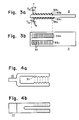
- the actuating web 11 is coupled to the slide 2.
- the coupling of the actuating web 11 to the slide 2 offers the advantage that only a single part, namely the slide 2, acts directly on the armature of the flame relay 1. A possibly asymmetrical loading of the armature by counter forces of different sizes of the parts to be moved by the armature is also avoided in this way.
- the end of the actuating web 11 (FIG. 2) facing the slider 2 is advantageous to form the end of the actuating web 11 (FIG. 2) facing the slider 2 as two resilient arms 31 and on the opposite inner sides of these arms 31 and on the To provide the surface of the slide 2 locking elements 32.
- the locking elements 32 can have the shape of teeth.
- the locking elements 32 are shown as teeth with a triangular profile, the two flanks forming the same angle against the reference plane. Any other tooth shapes are also possible. It is particularly advantageous to design the locking elements 32 as saw teeth, the steep tooth flanks of which are arranged such that the steep tooth flanks of the connecting partners press against one another in the pressure load occurring during the movement transmission. This asymmetrical tooth shape achieves an increased self-locking effect.
Landscapes
- Engineering & Computer Science (AREA)
- Chemical & Material Sciences (AREA)
- Combustion & Propulsion (AREA)
- Mechanical Engineering (AREA)
- General Engineering & Computer Science (AREA)
- Regulation And Control Of Combustion (AREA)
- Control Of Combustion (AREA)
Applications Claiming Priority (2)
| Application Number | Priority Date | Filing Date | Title |
|---|---|---|---|
| CH194689 | 1989-05-24 | ||
| CH1946/89 | 1989-05-24 |
Publications (3)
| Publication Number | Publication Date |
|---|---|
| EP0399134A2 true EP0399134A2 (fr) | 1990-11-28 |
| EP0399134A3 EP0399134A3 (fr) | 1991-01-30 |
| EP0399134B1 EP0399134B1 (fr) | 1993-05-26 |
Family
ID=4222292
Family Applications (1)
| Application Number | Title | Priority Date | Filing Date |
|---|---|---|---|
| EP90100288A Expired - Lifetime EP0399134B1 (fr) | 1989-05-24 | 1990-01-08 | Automate à brûleur |
Country Status (3)
| Country | Link |
|---|---|
| EP (1) | EP0399134B1 (fr) |
| DE (1) | DE59001538D1 (fr) |
| DK (1) | DK0399134T3 (fr) |
Family Cites Families (4)
| Publication number | Priority date | Publication date | Assignee | Title |
|---|---|---|---|---|
| GB858149A (en) * | 1958-03-19 | 1961-01-04 | Rheostatic Co Ltd | Improvements in fuel control means |
| US3923445A (en) * | 1974-04-10 | 1975-12-02 | Robertshaw Controls Co | Burner ignition system having safety switch with remote reset |
| CH604085A5 (fr) * | 1976-07-27 | 1978-08-31 | Landis & Gyr Ag | |
| FR2385985A1 (fr) * | 1977-03-30 | 1978-10-27 | Euroflex | Dispositif pour la commande d'un bruleur |
-
1990
- 1990-01-08 EP EP90100288A patent/EP0399134B1/fr not_active Expired - Lifetime
- 1990-01-08 DK DK90100288.1T patent/DK0399134T3/da active
- 1990-01-08 DE DE9090100288T patent/DE59001538D1/de not_active Expired - Fee Related
Also Published As
| Publication number | Publication date |
|---|---|
| DE59001538D1 (de) | 1993-07-01 |
| EP0399134B1 (fr) | 1993-05-26 |
| DK0399134T3 (da) | 1993-10-04 |
| EP0399134A3 (fr) | 1991-01-30 |
Similar Documents
| Publication | Publication Date | Title |
|---|---|---|
| EP2850629A1 (fr) | Commutateur électrique | |
| EP0060992A2 (fr) | Maquette d'essai et circuit d'évaluation pour détecteur de proximité à commande de machines | |
| DE9310461U1 (de) | Feuerungsautomat | |
| DE19641188C1 (de) | Schaltungsanordnung zur Energieversorgung eines Schaltgerät-Magnetantriebs | |
| DE2222258C2 (de) | Steuerschaltung für eine Brenneranlage. Anal: Landis & Gyr AG, Zug (Schweiz) | |
| EP0399134B1 (fr) | Automate à brûleur | |
| DE10022722C5 (de) | Sicherheitsschaltgerät zum sicheren Ein- und Ausschalten eines elektrischen Verbrauchers | |
| EP0615267A1 (fr) | Circuit de test des contacts d'interrupteur ou de relais | |
| DE2809993C3 (de) | Flammenwächterschaltung zur Überwachung einer Brennerflamme | |
| DE3022635C2 (de) | Steuerschaltung für eine Feuerungsanlage | |
| DE2344934A1 (de) | Flammenwaechter mit einem auf strahlen ansprechenden detektor | |
| DE3243108A1 (de) | Vorrichtung zum ein- und ausschalten eines elektrischen verbrauchers in einem kraftfahrzeug | |
| DE2425305C3 (de) | Schaltungsanordnung für Feuerungsautomaten | |
| DE19606255A1 (de) | Feuerungsautomat | |
| DE3688027T2 (de) | Elektrische ferngesteuerte Anlagen. | |
| DE2219159C3 (de) | Proze !!überwachungseinrichtung | |
| EP0314610B1 (fr) | Automate à brûleur | |
| DE2247918C3 (de) | Sicherheitsschaltung fur Feuerungsautomaten in Gas- und ölfeuerungsanlagen | |
| DE19752323C1 (de) | Wechselstromgespeiste Steuerschaltung für Gasmagnetventile | |
| DE2734003C2 (de) | Schaltungsanordnung zur netzspannungsschwankungskompensierten Leistungssteuerung eines netzbetriebenen Wärmegeräts, insbesondere einer Kochplatte | |
| AT257804B (de) | Impuls-Nadelzungen- oder Fadenwächtervorrichtung für Strickmaschinen | |
| DE2318484C3 (de) | Schaltungsanordnung mit zwei RC-Zeitkreisen | |
| DE2809994C3 (de) | Elektronische Sicherheitszeitschaltung für Gas- oder Ölbrenner | |
| DE2832149C2 (de) | Schaltungsanordnung für ein Gerät zur elektrischen Betäubung eines Tieres | |
| EP0440872A2 (fr) | Circuit d'allumage et de sécurité pour brûleur à gaz |
Legal Events
| Date | Code | Title | Description |
|---|---|---|---|
| PUAI | Public reference made under article 153(3) epc to a published international application that has entered the european phase |
Free format text: ORIGINAL CODE: 0009012 |
|
| AK | Designated contracting states |
Kind code of ref document: A2 Designated state(s): CH DE DK FR GB LI |
|
| PUAL | Search report despatched |
Free format text: ORIGINAL CODE: 0009013 |
|
| AK | Designated contracting states |
Kind code of ref document: A3 Designated state(s): CH DE DK FR GB LI |
|
| 17P | Request for examination filed |
Effective date: 19910301 |
|
| 17Q | First examination report despatched |
Effective date: 19921002 |
|
| GRAA | (expected) grant |
Free format text: ORIGINAL CODE: 0009210 |
|
| AK | Designated contracting states |
Kind code of ref document: B1 Designated state(s): CH DE DK FR GB LI |
|
| RAP2 | Party data changed (patent owner data changed or rights of a patent transferred) |
Owner name: LANDIS & GYR BUSINESS SUPPORT AG |
|
| GBT | Gb: translation of ep patent filed (gb section 77(6)(a)/1977) |
Effective date: 19930601 |
|
| REF | Corresponds to: |
Ref document number: 59001538 Country of ref document: DE Date of ref document: 19930701 |
|
| ET | Fr: translation filed | ||
| REG | Reference to a national code |
Ref country code: DK Ref legal event code: T3 |
|
| PLBE | No opposition filed within time limit |
Free format text: ORIGINAL CODE: 0009261 |
|
| STAA | Information on the status of an ep patent application or granted ep patent |
Free format text: STATUS: NO OPPOSITION FILED WITHIN TIME LIMIT |
|
| 26N | No opposition filed | ||
| PGFP | Annual fee paid to national office [announced via postgrant information from national office to epo] |
Ref country code: GB Payment date: 19961216 Year of fee payment: 8 |
|
| PGFP | Annual fee paid to national office [announced via postgrant information from national office to epo] |
Ref country code: DK Payment date: 19970124 Year of fee payment: 8 |
|
| PG25 | Lapsed in a contracting state [announced via postgrant information from national office to epo] |
Ref country code: GB Free format text: LAPSE BECAUSE OF NON-PAYMENT OF DUE FEES Effective date: 19980108 |
|
| PG25 | Lapsed in a contracting state [announced via postgrant information from national office to epo] |
Ref country code: DK Free format text: LAPSE BECAUSE OF NON-PAYMENT OF DUE FEES Effective date: 19980202 |
|
| GBPC | Gb: european patent ceased through non-payment of renewal fee |
Effective date: 19980108 |
|
| REG | Reference to a national code |
Ref country code: CH Ref legal event code: PFA Free format text: LANDIS & GYR BUSINESS SUPPORT AG TRANSFER- SIEMENS BUILDING TECHNOLOGIES AG C-IPR |
|
| REG | Reference to a national code |
Ref country code: DK Ref legal event code: EBP |
|
| PGFP | Annual fee paid to national office [announced via postgrant information from national office to epo] |
Ref country code: DE Payment date: 20060322 Year of fee payment: 17 |
|
| PGFP | Annual fee paid to national office [announced via postgrant information from national office to epo] |
Ref country code: CH Payment date: 20060411 Year of fee payment: 17 |
|
| PG25 | Lapsed in a contracting state [announced via postgrant information from national office to epo] |
Ref country code: CH Free format text: LAPSE BECAUSE OF NON-PAYMENT OF DUE FEES Effective date: 20070131 Ref country code: LI Free format text: LAPSE BECAUSE OF NON-PAYMENT OF DUE FEES Effective date: 20070131 |
|
| PG25 | Lapsed in a contracting state [announced via postgrant information from national office to epo] |
Ref country code: DE Free format text: LAPSE BECAUSE OF NON-PAYMENT OF DUE FEES Effective date: 20070801 |
|
| REG | Reference to a national code |
Ref country code: CH Ref legal event code: PL |
|
| PGFP | Annual fee paid to national office [announced via postgrant information from national office to epo] |
Ref country code: FR Payment date: 20070123 Year of fee payment: 18 |
|
| REG | Reference to a national code |
Ref country code: FR Ref legal event code: ST Effective date: 20081029 |
|
| PG25 | Lapsed in a contracting state [announced via postgrant information from national office to epo] |
Ref country code: FR Free format text: LAPSE BECAUSE OF NON-PAYMENT OF DUE FEES Effective date: 20080131 |