EP0399233B1 - Hubarbeitsbühne - Google Patents
Hubarbeitsbühne Download PDFInfo
- Publication number
- EP0399233B1 EP0399233B1 EP90107907A EP90107907A EP0399233B1 EP 0399233 B1 EP0399233 B1 EP 0399233B1 EP 90107907 A EP90107907 A EP 90107907A EP 90107907 A EP90107907 A EP 90107907A EP 0399233 B1 EP0399233 B1 EP 0399233B1
- Authority
- EP
- European Patent Office
- Prior art keywords
- wheels
- road
- undercarriage
- road wheels
- lower carriage
- Prior art date
- Legal status (The legal status is an assumption and is not a legal conclusion. Google has not performed a legal analysis and makes no representation as to the accuracy of the status listed.)
- Expired - Lifetime
Links
- 230000003028 elevating effect Effects 0.000 title claims abstract 6
- 238000010276 construction Methods 0.000 description 2
- 239000007787 solid Substances 0.000 description 1
Images
Classifications
-
- E—FIXED CONSTRUCTIONS
- E04—BUILDING
- E04G—SCAFFOLDING; FORMS; SHUTTERING; BUILDING IMPLEMENTS OR AIDS, OR THEIR USE; HANDLING BUILDING MATERIALS ON THE SITE; REPAIRING, BREAKING-UP OR OTHER WORK ON EXISTING BUILDINGS
- E04G1/00—Scaffolds primarily resting on the ground
- E04G1/18—Scaffolds primarily resting on the ground adjustable in height
- E04G1/22—Scaffolds having a platform on an extensible substructure, e.g. of telescopic type or with lazy-tongs mechanism
-
- B—PERFORMING OPERATIONS; TRANSPORTING
- B66—HOISTING; LIFTING; HAULING
- B66F—HOISTING, LIFTING, HAULING OR PUSHING, NOT OTHERWISE PROVIDED FOR, e.g. DEVICES WHICH APPLY A LIFTING OR PUSHING FORCE DIRECTLY TO THE SURFACE OF A LOAD
- B66F11/00—Lifting devices specially adapted for particular uses not otherwise provided for
- B66F11/04—Lifting devices specially adapted for particular uses not otherwise provided for for movable platforms or cabins, e.g. on vehicles, permitting workmen to place themselves in any desired position for carrying out required operations
- B66F11/042—Lifting devices specially adapted for particular uses not otherwise provided for for movable platforms or cabins, e.g. on vehicles, permitting workmen to place themselves in any desired position for carrying out required operations actuated by lazy-tongs mechanisms or articulated levers
Definitions
- the invention relates to an aerial work platform with an undercarriage, on the four corners of which support wheels are arranged, on which the undercarriage stands and can be moved during use, and to which further road wheels suitable for road transport are fastened between the support wheels, the position of the support and road wheels are adjustable in height relative to each other in such a way that the road wheels do not touch the ground during use of the undercarriage and the support wheels during transport of the undercarriage.
- the undercarriage of such aerial work platforms is supported by four support wheels which are mounted on the four corners of the undercarriage and must be relatively unyielding so that the work platform does not fluctuate when the work platform is raised.
- the support wheels are usually made of solid rubber. With these support wheels, the working platform can be moved over short distances. These support wheels are not suitable for transport over long distances on roads, where the working platform is attached to a truck as a trailer.
- a generic aerial work platform is known from US Pat. No. 3,516,512.
- the support wheels are screwed down by spindles for work, so that the undercarriage together with the road wheels is raised so far that the road wheels no longer touch the ground.
- Such a construction is constructive and difficult to use.
- the mast must be removed for road transport, since the platform can be moved up and down.
- the driving stability of the platform is insufficient when the training wheels are raised.
- the object of the invention is to improve an aerial work platform of the type mentioned at the outset in such a way that a changeover from operations to road transport and vice versa can be carried out easily, quickly, easily and with the greatest possible safety, and in which the driving stability during transport is increased is.
- the support wheels are fixed immovably in relation to the undercarriage, so that the highest level of safety can be achieved in work.
- the road bikes are driven upwards so that they do not interfere with work. If the aerial work platform is to be moved over greater distances, the road wheels are driven down so far that the support wheels are lifted off the ground. In this condition, the undercarriage can be attached to a truck as a trailer.
- tandem axle makes it possible in a structurally particularly simple way to fasten the four road wheels up and down on the undercarriage.
- Such academic axes can already be purchased from third parties.
- the axles of the road wheels can be moved up and down by means of hydraulically or pneumatically operated cylinder-piston units. It is preferably proposed that the work platform has a lifting device with scissor-shaped support members.
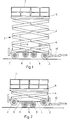
- the aerial work platform has an undercarriage 1, on the four corner areas of which a support wheel 2 is mounted. These support wheels 2 are not movable in height with respect to the undercarriage 1, i.e. the axes of the support wheels 2 cannot be adjusted at least in height relative to the undercarriage 1.
- a lifting device 3 On the top of the undercarriage 1, a lifting device 3 is attached, which has scissor-shaped lifting members 4, with which a horizontal working platform 5 is movable up and down. For this up and down are at the scissor-shaped members 4 cylinder-piston units 6 attached, which are acted upon hydraulically or pneumatically.
- the top of the work platform 5 is completely surrounded by a railing 7.
- road wheels 8 are attached, the axes of which are formed by a tandem axis which is parallel to the axes of the support wheels 2.
- the road wheels 8 can be raised and lowered relative to the undercarriage 1, the road wheels 8 being raised in the uppermost position to such an extent that their underside is higher than the underside of the support wheels 2 and, in the lowered state, the underside of the road wheels 8 is lower than the undersides the support wheels 2, so that in the lowered state the road wheels 8 raise the undercarriage 1 to such an extent that there is a sufficient distance between the support wheels 2 and the road surface.
- a high load capacity is achieved because two pairs of road wheels 8 are attached to a tandem axle.
- the two pairs of wheels can be moved vertically up and down by suitable constructions. It is structurally particularly simple if the road wheels 8 or their axles are mounted on the lower free ends of pivotable arms 9 which are articulated with their upper ends on the undercarriage 1. It is structurally particularly simple if the wheel axles or the arms 9 are moved up and down hydraulically or pneumatically by cylinder-piston units. Since the work platform 5 is already actuated hydraulically or pneumatically, it is structurally inexpensive to use the same actuation system for raising and lowering the road wheels 8.
- a fork 10 is articulated on the front side of the undercarriage 1 and has an eyelet at its front free end for attachment to a towing vehicle.
Landscapes
- Engineering & Computer Science (AREA)
- Structural Engineering (AREA)
- Mechanical Engineering (AREA)
- Architecture (AREA)
- Life Sciences & Earth Sciences (AREA)
- Geology (AREA)
- Civil Engineering (AREA)
- Forklifts And Lifting Vehicles (AREA)
- Handcart (AREA)
- Electrical Discharge Machining, Electrochemical Machining, And Combined Machining (AREA)
- Inorganic Insulating Materials (AREA)
Description
- Die Erfindung betrifft eine Hubarbeitsbühne mit einem Unterwagen, an dessen vier Ecken Stützräder angeordnet sind, auf denen der Unterwagen während des Einsatzes steht und verschiebbar ist und an dem zwischen den Stützrädern weitere, für den Straßentransport geeignete Straßenräder befestigt sind, wobei die Stellung der Stütz- und Straßenräder in der Höhe relativ zueinander derart verstellbar ist, daß die Straßenräder während des Einsatzes des Unterwagens und die Stützräder während des Transports des Unterwagens den Boden nicht berühren.
- Der Unterwagen solcher Hubarbeitsbühnen wird während des Einsatzes der Arbeitsbühne von vier Stützrädern getragen, die an den vier Ecken des Unterwagens gelagert sind und so verhältnismäßig unnachgiebig sein müssen, damit bei angehobener Arbeitsbühne diese nicht schwankt. Hierzu sind die Stützräder meist aus Vollgummi gefertigt. Mit diesen Stützrädern kann die Arbeitsbühne über kurze Entfernungen bewegt werden. Für einen Transport über größere Entfernungen auf Straßen, bei dem die Arbeitsbühne als Anhänger an einen Lastkraftwagen befestigt wird, sind diese Stützräder nicht geeignet.
- Aus der US-PS 3 516 512 ist eine gattungsgemäße Hubarbeitsbühne bekannt. Bei dieser Arbeitsühne werden für den Arbeitsbetrieb die Stützräder durch Spindeln nach unten geschraubt, so daß der Unterwagen zusammen mit den Straßenrädern so weit angehoben wird, daß die Straßenräder den Boden nicht mehr berühren. Eine solche Konstruktion ist konstruktiv und in der Handhabung aufwendig. Darüber hinaus muß für den Straßentransport der Mast abmontiert werden, da die Bühne auf- und abfahrbar ist. Zudem ist die Fahrstabilität der Bühne bei angehobenen Stützrädern unzureichend.
- Aufgabe der Erfindung ist es, eine Hubarbeitsbühne der eingangs genannten Art so zu verbessern, daß ein Umstellen vom Einsatzbetrieb zum Straßentransport und umgekehrt bei geringem konstruktiven Aufwand leicht, schnell, einfach und bei größter Sicherheit durchführbar ist, und bei der die Fahrstabilität während des Transports erhöht ist.
- Diese Aufgabe wird erfindungsgemäß dadurch gelöst, daß die Straßenräder gegenüber dem Unterwagen für den Straßentransport so weit nach unten verfahrbar sind, daß die Stützräder vom Boden abgehoben sind und daß vier Straßenräder an dem Unterwagen auf- und ab beweglich befestigt sind, wobei die vier Straßenräder von einer Tandemachse gebildet sind.
- Die Stützräder sind gegenüber dem Unterwagen in ihrer Höhe unbeweglich befestigt, so daß im Arbeitsbetrieb höchste Sicherheit erreichbar ist. Die Straßenräder sind hierbei nach oben gefahren, so daß sie während des Arbeitseinsatzes nicht stören. Soll die Hubarbeitsbühne über größere Entfernungen bewegt werden, so werden die Straßenräder so weit nach unten gefahren, daß die Stützräder vom Boden abgehoben sind. In diesem Zustand kann der Unterwagen als Anhänger an einem Lastkraftwagen befestigt werden.
- Die Verwendung einer Tandemachse ermöglicht es auf konstruktiv besonders einfache Weise, die vier Straßenräder an dem Unterwagen auf- und ab beweglich zu befestigen. Solche Tademachsen können bereits fertig von Dritten bezogen werden.
- Eine besonders einfache und sichere Handhabung wird dann erreicht, wenn die Achsen der Straßenräder durch hydraulisch oder pneumatisch betriebene Zylinder-Kolben-Aggregate auf- und abbeweglich sind. Vorzugsweise wird vorgeschlagen, daß die Arbeitsbühne eine Hubvorrichtung mit scherenförmigen Traggliedern aufweist.
- Ein Ausführungsbeispiel der Erfindung ist in der Zeichnung dargestellt und wird im folgenden näher beschrieben.
- Es zeigen
- Figur 1 die Hubarbeitsbühne während des Arbeitseinsatzes mit angehobenen Straßenrädern und
- Figur 2 die Hubarbeitsbühne für den Straßentransport mit abgesenkten Straßenrädern.
- Die Hubarbeitsbühne weist einen Unterwagen 1 auf, an dessen vier Eckenbereichen je ein Stützrad 2 gelagert ist. Diese Stützräder 2 sind gegenüber dem Unterwagen 1 in ihrer Höhe nicht beweglich, d.h. die Achsen der Stützräder 2 können gegenüber dem Unterwagen 1 zumindest in ihrer Höhe nicht verstellt werden.
- Auf der Oberseite des Unterwagens 1 ist eine Hubvorrichtung 3 befestigt, die scherenförmige Hubglieder 4 aufweist, mit denen eine waagerechte Arbeitsbühne 5 auf und ab beweglich ist. Für diese Auf- und Abbegung sind an den scherenförmigen Gliedern 4 Zylinder-Kolben-Aggregate 6 befestigt, die hydraulisch oder pneumatisch beaufschlagt sind. Die Arbeitsbühne 5 ist an ihrer Oberseite rundum von einem Geländer 7 umgeben.
- An der Unterseite des Unterwagens 1 sind Straßenräder 8 angebracht, deren Achsen durch eine Tandemachse gebildet sind, die parallel zu den Achsen der Stützräder 2 liegt. Die Straßenräder 8 sind gegenüber dem Unterwagen 1 anheb- und absenkbar, wobei in der obersten Stellung die Straßenräder 8 soweit angehoben sind, daß deren Unterseite höher liegt als die Unterseite der Stützräder 2 und im abgesenkten Zustand die Unterseite der Straßenräder 8 tiefer liegt als die Unterseiten der Stützräder 2, so daß im abgesenkten Zustand die Straßenräder 8 den Unterwagen 1 so weit anheben, daß ein ausreichender Abstand zwischen den Stützrädern 2 und dem Straßenbelag ist. Dabei wird eine hohe Tragkraft erreicht, da zwei Paare von Straßenrädern 8 an einer Tandemachse befestigt sind.
- Die zwei Räderpaare sind sind durch geeignete Konstruktionen senkrecht auf- und abbeweglich. Konstruktiv besonders einfach ist es, wenn die Straßenräder 8 bzw. deren Achsen an den unteren freien Enden verschwenkbarer Arme 9 gelagert sind, die mit ihren oberen Enden am Unterwagen 1 angelenkt sind. Hierbei ist es konstruktiv besonders einfach, wenn die Radachsen bzw. die Arme 9 durch Zylinder-Kolben-Aggregate hydraulisch oder pneumatisch auf- und ab bewegt werden. Da bereits die Arbeitsbühne 5 hydraulisch oder pneumatisch betätigt wird, ist es konstruktiv wenig aufwendig, dasselbe Betätigungssystem für das Anheben und Absenken der Straßenräder 8 zu verwenden.
- An der vorderen Seite des Unterwagens 1 ist eine Gabel 10 angelenkt, die an ihrem vorderen freien Ende eine Öse zur Befestigung an einem Zugwagen aufweist.
Claims (3)
- Hubarbeitsbühne mit einem Unterwagen (1), an dessen vier Ecken Stützräder (2) angeordnet sind, auf denen der Unterwagen (1) während des Einsatzes steht und verschiebbar ist und an dem zwischen den Stützrädern (2) weitere, für den Straßentransport geeignete Straßenräder (8) befestigt sind, wobei die Stellung der Stütz- (2) und Straßenräder (8) in der Höhe relativ zueinander derart verstellbar ist, daß die Straßenräder (8) während des Einsatzes des Unterwagens (1) und die Stützräder während des Transports des Unterwagens (1) den Boden nicht berühren, dadurch gekennzeichnet, daß die Straßenräder (8) gegenüber dem Unterwagen (1) für den Straßentransport so weit nach unten verfahrbar sind, daß die Stützräder (2) vom Boden abgehoben sind und daß vier Straßenräder (8) an dem Unterwagen (1) auf- und ab beweglich befestigt sind, wobei die vier Straßenräder (8) von einer Tandemachse gebildet sind.
- Hubarbeitsbühne nach Anspruch 1, dadurch gekennzeichnet, daß die Achsen der Straßenräder (8) durch hydraulisch oder pneumatisch betriebene Zylinder-Kolben-Aggregate auf- und abbeweglich sind.
- Hubarbeitsbühne nach einem der vorhergehenden Ansprüche, dadurch gekennzeichnet, daß die Arbeitsbühne (5) eine Hubvorrichtung (3) mit scherenförmigen Traggliedern (4) aufweist.
Priority Applications (1)
| Application Number | Priority Date | Filing Date | Title |
|---|---|---|---|
| AT90107907T ATE83823T1 (de) | 1989-04-26 | 1990-04-26 | Hubarbeitsbuehne. |
Applications Claiming Priority (2)
| Application Number | Priority Date | Filing Date | Title |
|---|---|---|---|
| DE3913645A DE3913645C1 (de) | 1989-04-26 | 1989-04-26 | |
| DE3913645 | 1989-04-26 |
Publications (2)
| Publication Number | Publication Date |
|---|---|
| EP0399233A1 EP0399233A1 (de) | 1990-11-28 |
| EP0399233B1 true EP0399233B1 (de) | 1992-12-23 |
Family
ID=6379439
Family Applications (1)
| Application Number | Title | Priority Date | Filing Date |
|---|---|---|---|
| EP90107907A Expired - Lifetime EP0399233B1 (de) | 1989-04-26 | 1990-04-26 | Hubarbeitsbühne |
Country Status (3)
| Country | Link |
|---|---|
| EP (1) | EP0399233B1 (de) |
| AT (1) | ATE83823T1 (de) |
| DE (2) | DE3913645C1 (de) |
Cited By (1)
| Publication number | Priority date | Publication date | Assignee | Title |
|---|---|---|---|---|
| KR100914485B1 (ko) | 2007-11-30 | 2009-08-28 | 주식회사 신성에프에이 | 상부레일 설치용 작업대차 |
Families Citing this family (1)
| Publication number | Priority date | Publication date | Assignee | Title |
|---|---|---|---|---|
| DE102009027972A1 (de) * | 2009-07-23 | 2011-02-03 | Waldner Labor- Und Schuleinrichtungen Gmbh | Scherenhubvorrichtung |
Family Cites Families (3)
| Publication number | Priority date | Publication date | Assignee | Title |
|---|---|---|---|---|
| US3516512A (en) * | 1968-03-06 | 1970-06-23 | Eisenbau Karl Ladwig Bsb | Mobile scaffold |
| US3889778A (en) * | 1973-07-26 | 1975-06-17 | Gerald Dean Dotts | Platform lift |
| FR2317218A1 (fr) * | 1975-07-07 | 1977-02-04 | Systems Manufacturing Co | Elevateur a croisillons articules |
-
1989
- 1989-04-26 DE DE3913645A patent/DE3913645C1/de not_active Expired - Lifetime
-
1990
- 1990-04-26 EP EP90107907A patent/EP0399233B1/de not_active Expired - Lifetime
- 1990-04-26 DE DE9090107907T patent/DE59000636D1/de not_active Expired - Lifetime
- 1990-04-26 AT AT90107907T patent/ATE83823T1/de not_active IP Right Cessation
Cited By (1)
| Publication number | Priority date | Publication date | Assignee | Title |
|---|---|---|---|---|
| KR100914485B1 (ko) | 2007-11-30 | 2009-08-28 | 주식회사 신성에프에이 | 상부레일 설치용 작업대차 |
Also Published As
| Publication number | Publication date |
|---|---|
| EP0399233A1 (de) | 1990-11-28 |
| ATE83823T1 (de) | 1993-01-15 |
| DE59000636D1 (de) | 1993-02-04 |
| DE3913645C1 (de) | 1990-10-31 |
Similar Documents
| Publication | Publication Date | Title |
|---|---|---|
| DE2018218C3 (de) | Containerverfahrgerät zum Anschluß an ein Fahrzeug mittels Kupplung | |
| EP0405230A1 (de) | Hebeeinrichtung zum Anheben von Fahrzeugen | |
| DE3017456A1 (de) | Hochregalstapler | |
| DE3642700C2 (de) | ||
| EP0454709B1 (de) | Fahrzeug, insbesondere fahrgestell einer brückenuntersichtvorrichtung | |
| EP0045398A1 (de) | Kombinierte Wechsel-Kipp-Einrichtung für Nutzfahrzeugaufbauten | |
| DE2837398A1 (de) | Fahrzeugkran | |
| DE3913645C1 (de) | ||
| EP0650421A1 (de) | Vorrichtung zum aufnehmen und anheben eines containers | |
| DE3336638C2 (de) | Fahrzeugkran hoher Traglast mit verlängerbarem Ausleger, insbesondere Teleskopausleger | |
| EP0612678B1 (de) | Fahrbare Schrägrampe | |
| DE2856350A1 (de) | Fahrzeug zum transport von coils | |
| DE2653278A1 (de) | Tieflader, insbesondere auflieger fuer den strassentransport von sperrigen lasten, z.b. von glasscheiben in aufrechter stellung | |
| EP1077169A2 (de) | Flurförderzeug mit Lastrollen | |
| DE2832393C2 (de) | Transportfahrzeug, insbesondere Tieflade- Straßenfahrzeug mit veränderbarer Bodenfreiheit | |
| DE19620944C1 (de) | Abstützeinrichtung mit Querbewegungsantrieb für mobile Arbeitsgeräte | |
| AT389680B (de) | Anhaenger zum abschleppen von fahrzeugen | |
| DE9306949U1 (de) | Ladevorrichtung für Lastträger | |
| DE19728822A1 (de) | Anbaunachlauffahrwerk | |
| DE3522566A1 (de) | Vorrichtung fuer motorfahrzeuge | |
| DE3829795C1 (en) | Supporting device for lifting vehicles under the wheels | |
| DE69200139T2 (de) | Hydraulisch betätigter, auf Scheren gestützter Hebewagen. | |
| DE8915671U1 (de) | Hubarbeitsbühne | |
| DE447603C (de) | Elektrischer Hub- und Stapelkarren mit einer mittels Parallellenkerpaare heb- und senkbaren Ladeplattform | |
| DE1630670C3 (de) | Ladegerät für StraBenlastfahrzeuge |
Legal Events
| Date | Code | Title | Description |
|---|---|---|---|
| PUAI | Public reference made under article 153(3) epc to a published international application that has entered the european phase |
Free format text: ORIGINAL CODE: 0009012 |
|
| AK | Designated contracting states |
Kind code of ref document: A1 Designated state(s): AT BE CH DE DK ES FR GB GR IT LI NL SE |
|
| 17P | Request for examination filed |
Effective date: 19910313 |
|
| 17Q | First examination report despatched |
Effective date: 19911016 |
|
| GRAA | (expected) grant |
Free format text: ORIGINAL CODE: 0009210 |
|
| AK | Designated contracting states |
Kind code of ref document: B1 Designated state(s): AT BE CH DE DK ES FR GB GR IT LI NL SE |
|
| PG25 | Lapsed in a contracting state [announced via postgrant information from national office to epo] |
Ref country code: IT Free format text: LAPSE BECAUSE OF FAILURE TO SUBMIT A TRANSLATION OF THE DESCRIPTION OR TO PAY THE FEE WITHIN THE PRESCRIBED TIME-LIMIT;WARNING: LAPSES OF ITALIAN PATENTS WITH EFFECTIVE DATE BEFORE 2007 MAY HAVE OCCURRED AT ANY TIME BEFORE 2007. THE CORRECT EFFECTIVE DATE MAY BE DIFFERENT FROM THE ONE RECORDED. Effective date: 19921223 Ref country code: GR Free format text: LAPSE BECAUSE OF FAILURE TO SUBMIT A TRANSLATION OF THE DESCRIPTION OR TO PAY THE FEE WITHIN THE PRESCRIBED TIME-LIMIT Effective date: 19921223 Ref country code: BE Effective date: 19921223 Ref country code: DE Effective date: 19921223 Ref country code: ES Free format text: THE PATENT HAS BEEN ANNULLED BY A DECISION OF A NATIONAL AUTHORITY Effective date: 19921223 Ref country code: DK Effective date: 19921223 Ref country code: SE Effective date: 19921223 |
|
| REF | Corresponds to: |
Ref document number: 83823 Country of ref document: AT Date of ref document: 19930115 Kind code of ref document: T |
|
| ET | Fr: translation filed | ||
| GBT | Gb: translation of ep patent filed (gb section 77(6)(a)/1977) |
Effective date: 19921217 |
|
| REF | Corresponds to: |
Ref document number: 59000636 Country of ref document: DE Date of ref document: 19930204 |
|
| PG25 | Lapsed in a contracting state [announced via postgrant information from national office to epo] |
Ref country code: AT Effective date: 19930426 |
|
| PG25 | Lapsed in a contracting state [announced via postgrant information from national office to epo] |
Ref country code: LI Effective date: 19930430 Ref country code: CH Effective date: 19930430 |
|
| PLBE | No opposition filed within time limit |
Free format text: ORIGINAL CODE: 0009261 |
|
| STAA | Information on the status of an ep patent application or granted ep patent |
Free format text: STATUS: NO OPPOSITION FILED WITHIN TIME LIMIT |
|
| PG25 | Lapsed in a contracting state [announced via postgrant information from national office to epo] |
Ref country code: NL Effective date: 19931101 |
|
| 26N | No opposition filed | ||
| NLV4 | Nl: lapsed or anulled due to non-payment of the annual fee | ||
| PG25 | Lapsed in a contracting state [announced via postgrant information from national office to epo] |
Ref country code: FR Effective date: 19931229 |
|
| REG | Reference to a national code |
Ref country code: CH Ref legal event code: PL |
|
| REG | Reference to a national code |
Ref country code: FR Ref legal event code: ST |
|
| PG25 | Lapsed in a contracting state [announced via postgrant information from national office to epo] |
Ref country code: GB Effective date: 19940426 |
|
| GBPC | Gb: european patent ceased through non-payment of renewal fee |
Effective date: 19940426 |