EP0399353A1 - Dichtung für Container, insbesondere Kühlcontainer - Google Patents
Dichtung für Container, insbesondere Kühlcontainer Download PDFInfo
- Publication number
- EP0399353A1 EP0399353A1 EP90109215A EP90109215A EP0399353A1 EP 0399353 A1 EP0399353 A1 EP 0399353A1 EP 90109215 A EP90109215 A EP 90109215A EP 90109215 A EP90109215 A EP 90109215A EP 0399353 A1 EP0399353 A1 EP 0399353A1
- Authority
- EP
- European Patent Office
- Prior art keywords
- door
- profile
- seal according
- sealing
- container
- Prior art date
- Legal status (The legal status is an assumption and is not a legal conclusion. Google has not performed a legal analysis and makes no representation as to the accuracy of the status listed.)
- Granted
Links
- 238000007789 sealing Methods 0.000 title claims abstract description 42
- 239000013536 elastomeric material Substances 0.000 claims abstract description 3
- 229920001971 elastomer Polymers 0.000 claims description 4
- 150000001875 compounds Chemical class 0.000 claims description 3
- 239000000806 elastomer Substances 0.000 claims description 2
- 238000001746 injection moulding Methods 0.000 claims description 2
- 229920000459 Nitrile rubber Polymers 0.000 claims 2
- 229920001577 copolymer Polymers 0.000 claims 1
- 239000000203 mixture Substances 0.000 claims 1
- 229920001084 poly(chloroprene) Polymers 0.000 claims 1
- 229920002379 silicone rubber Polymers 0.000 claims 1
- 239000004945 silicone rubber Substances 0.000 claims 1
- 239000000126 substance Substances 0.000 claims 1
- 230000008961 swelling Effects 0.000 claims 1
- 238000004873 anchoring Methods 0.000 abstract description 4
- 241000251131 Sphyrna Species 0.000 abstract 3
- 230000000284 resting effect Effects 0.000 abstract 1
- 238000005260 corrosion Methods 0.000 description 1
- 230000007797 corrosion Effects 0.000 description 1
- 230000003993 interaction Effects 0.000 description 1
- 239000000463 material Substances 0.000 description 1
- 238000009420 retrofitting Methods 0.000 description 1
Images

Classifications
-
- E—FIXED CONSTRUCTIONS
- E06—DOORS, WINDOWS, SHUTTERS, OR ROLLER BLINDS IN GENERAL; LADDERS
- E06B—FIXED OR MOVABLE CLOSURES FOR OPENINGS IN BUILDINGS, VEHICLES, FENCES OR LIKE ENCLOSURES IN GENERAL, e.g. DOORS, WINDOWS, BLINDS, GATES
- E06B7/00—Special arrangements or measures in connection with doors or windows
- E06B7/16—Sealing arrangements on wings or parts co-operating with the wings
- E06B7/22—Sealing arrangements on wings or parts co-operating with the wings by means of elastic edgings, e.g. elastic rubber tubes; by means of resilient edgings, e.g. felt or plush strips, resilient metal strips
- E06B7/23—Plastic, sponge rubber, or like strips or tubes
- E06B7/2305—Plastic, sponge rubber, or like strips or tubes with an integrally formed part for fixing the edging
-
- B—PERFORMING OPERATIONS; TRANSPORTING
- B60—VEHICLES IN GENERAL
- B60J—WINDOWS, WINDSCREENS, NON-FIXED ROOFS, DOORS, OR SIMILAR DEVICES FOR VEHICLES; REMOVABLE EXTERNAL PROTECTIVE COVERINGS SPECIALLY ADAPTED FOR VEHICLES
- B60J10/00—Sealing arrangements
- B60J10/80—Sealing arrangements specially adapted for opening panels, e.g. doors
- B60J10/86—Sealing arrangements specially adapted for opening panels, e.g. doors arranged on the opening panel
- B60J10/87—Sealing arrangements specially adapted for opening panels, e.g. doors arranged on the opening panel with additional seals on the panel side
Definitions
- the invention relates to a seal for containers, in particular refrigerated containers, according to the preamble of claim 1.
- a generic seal is known from DE-C-19 22 789 and DE-A-38 08 520.
- Such a container seal has previously been anchored by means of a mechanical fastening system in the form of additional strips with screws, pop rivets or the like on the end face of the door or door leaf.
- fastening elements of this type frequently lead to the elastomer profile soon wearing out, in particular due to the interaction of different materials with different properties (for example hardness, coefficient of expansion, corrosion).
- the replacement of the seals, if necessary involves complex and costly additional work.
- the existing sealing systems do not meet the highest requirements with regard to their sealing performance, especially not if there is a large temperature gradient between the container interior and the container environment, which is usually the case with refrigerated containers (e.g. inside temperature: -20 ° C, outside temperature : + 30 ° C).
- the object of the invention is now to simplify the anchoring of the sealing profile made of elastomeric material in the context of a more effective seal, in particular in refrigerated containers, in such a way that the above-mentioned fastening systems are eliminated, and the like. from the point of view of stable anchoring on the one hand and easy interchangeability on the other. This problem is solved by the characterizing part of claim 1.
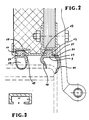
- the individual parts in the area of the gap to be sealed are: Container door (1) Front surface (2) of the container door Hinge (3) Outside of door (4) Inside of door (5) Door Jamb (6) Corner area (7) of the door jamb Gap (8) External sealing profile (9) with sealing lips (10, 11) External sealing profile (9) with an additional groove (29) which is filled with sealing compound (30) Inner sealing profile (14) with sealing lips (15, 16) Inner sealing profile (27) with tubular sealing part (28) Hammer head (12, 17) arched barb base (13) Barb base (18) in combination with profile channel (19) Rails (20, 24) Retaining flanges (21, 22, 25, 26) Rail corner area (23)
- the hammer head (12) of the outer sealing profile (9), which rests on the holding flange (21), is directed towards the outside of the door (4).
- the opposite arcuate (beak-shaped) barb foot (13) runs at an angle of approximately 45 ° to the rail corner (23), where it is anchored by means of the holding flange (22).
- This profile structure in the anchoring area of the C-shaped rail (20) ensures a particularly high pull-out strength, which is of particular importance in the case of the outer sealing profile (9).
- the inner sealing profile (14) in addition to the pull-out strength, the highest possible tolerance compensation when sealing the gap (8) is required.
- the tolerance compensation is achieved here by the elastic barb foot (18).
- this is essentially triangular in shape, in the clamping area of which there is a channel extending in the longitudinal direction of the profile, which is arranged approximately at the same height as the holding flanges (25, 26) and whose cross-sectional area is oval-shaped.
- the hammer head (17) of the inner sealing profile (14) is directed towards the inside of the door (5). This measure also ensures a high pull-out strength for the inner sealing profile.
- the inner profile (14) according to FIG. 1 has two arcuate sealing lips (15, 16), which (viewed from the outside of the door 4) are concave. 2, the sealing part of the inner profile (27) is designed as a hose (28). In this variant, the sealing performance and tolerance compensation of the inner profile is particularly pronounced.
- Gap width s ⁇ 10 mm Depth v (inside) ⁇ 4 mm Base width w (inside) ⁇ 20 mm
- the outer sealing profile (9) according to FIG. 2 is also provided with a groove (29) running in the longitudinal direction of the profile, which is filled with a sealing compound (30).
- a container usually has two door leaves (DE-A-38 08 520, DE-C-19 22 789), in which case the gap between the two door leaves must of course also be sealed.
- the right door wing (viewed from the outside) is equipped all round (i.e. all four end faces) with the seal according to the invention.
- the left door wing is only provided with this seal on three end faces, while the rails of that end face, which is opposite the end face of the right door wing, with a compensation or.
- Filling profile can be equipped to create a smooth end surface.
- the four frame corners are expediently produced by the injection molding process.
Landscapes
- Engineering & Computer Science (AREA)
- Civil Engineering (AREA)
- Structural Engineering (AREA)
- Mechanical Engineering (AREA)
- Refrigerator Housings (AREA)
- Packages (AREA)
- Specific Sealing Or Ventilating Devices For Doors And Windows (AREA)
Abstract
Description
- Die Erfindung betrifft eine Dichtung für Container, insbesondere Kühlcontainer, gemäß Oberbegriff des Anspruchs 1.
- Eine gattungsgemäße Dichtung ist aus der DE-C-19 22 789 und der DE-A-38 08 520 bekannt. Dabei wird eine derartige Container-Dichtung bisher mittels eines mechanischen Befestigungssystems in Form von Zusatzleisten mit Schrauben, Popnieten oder dgl. an der Stirnseite der Tür bzw. des Türflügels verankert. Derartige Befestigungselemente führen jedoch nicht selten zu einem baldigen Verschleiß des Elastomerprofils, insbesondere bedingt durch das Zusammenwirken von verschiedenen Werkstoffen mit unterschiedlichen Eigenschaften (z.B. Härte, Ausdehnungskoeffizient, Korrosion). Zudem ist der Austausch der Dichtungen bei Bedarfsfall (Erneuerung, Umrüstung) mit aufwendigen und kostspieligen Zusatzarbeiten verbunden. Darüber hinaus genügen die bisherigen Abdichtungssysteme hinsichtlich ihrer Dichtleistung nicht den höchsten Anforderungen, vor allem dann nicht, wenn zwischen dem Containerinneren und der Containerumgebung ein großes Temperaturgefälle existiert, was bei Kühlcontainern in der Regel der Fall ist (z.B. Innentemperatur: -20°C, Außentemperatur: +30°C).
- Aufgabe der Erfindung ist es nun, im Rahmen einer wirksameren Abdichtung, insbesondere bei Kühlcontainern, die Verankerung des Dichtungsprofils aus elastomerem Werkstoff so zu vereinfachen, daß die oben erwähnten Befestigungssysteme entfallen, u.z. unter dem Gesichtspunkt einer stabilen Verankerung einerseits und einer leichten Austauschbarkeit andererseits. Gelöst wird diese Aufgabe durch das Kennzeichen des Anspruchs 1.
- Die Erfindung wird im folgenden anhand von Ausführungsbeispielen näher erläutert. Es zeigen (in Draufsicht):
- Fig. 1, 2 die Doppeldichtung zwischen Container-Tür und Türpfosten;
- Fig. 3 die C-förmige Schiene und ihre Dimensionsparameter.
- Die einzelnen Teile im Bereich des abzudichtenden Spaltes sind:
Container-Tür (1)
Stirnfläche (2) der Container-Tür
Scharnier (3)
Türaußenseite (4)
Türinnenseite (5)
Türpfosten (6)
Eckbereich (7) des Türpfostens
Spalt (8)
Außendichtungsprofil (9) mit Dichtlippen (10, 11)
Außendichtungsprofil (9) mit zusätzlicher Nut (29), die mit Versiegelungsmasse (30) gefüllt ist
Innendichtungsprofil (14) mit Dichtlippen (15, 16)
Innendichtungsprofil (27) mit schlauchförmigem Dichtteil (28)
Hammerkopf (12, 17)
bogenförmiger Widerhakenfuß (13)
Widerhakenfuß (18) in Kombination mit Profilkanal (19)
Schienen (20, 24)
Halteflansche (21, 22, 25, 26)
Schieneneckbereich (23) - Nach Fig. 1 ist der Hammerkopf (12) des Außendichtungsprofils (9), der auf dem Halteflansch (21) aufsitzt, zur Türaußenseite (4) gerichtet. Der gegenüberliegende bogenförmige (schnabelförmige) Widerhakenfuß (13) verläuft in einem Winkel von etwa 45° auf die Schienenecke (23) zu, wo er mittels des Halteflansches (22) verankert ist. Durch diesen Profilaufbau im Verankerungsbereich der C-förmigen Schiene (20) ist eine besonders hohe Ausreißfestigkeit gewährleistet, was gerade bei dem Außendichtungsprofil (9) von wesentlicher Bedeutung ist. Bei dem Innendichtungsprofil (14) wird neben der Ausreißfestigkeit auch ein möglichst hoher Toleranzäusgleich beim Abdichten des Spaltes (8) gefordert. Der Toleranzausgleich wird hier durch den elastischen Widerhakenfuß (18) erreicht. Dieser ist im Querschnitt gesehen im wesentlichen dreiecksförmig gestaltet, in dessen Klemmbereich ein in Profillängsrichtung verlaufender Kanal vorhanden ist, der in etwa höhengleich mit den Halteflanschen (25, 26) angeordnet und dessen Querschnittsfläche ovalförmig ausgebildet ist. Der Hammerkopf (17) des Innendichtungsprofils (14) ist zur Türinnenseite (5) gerichtet. Durch diese Maßnahme ist ebenfalls eine hohe Ausreißfestigkeit beim Innendichtungsprofil gewährleistet.
- Das Innenprofil (14) nach Fig. 1 weist zwei bogenförmige Dichtlippen (15, 16) auf, die (von der Türaußenseite 4 betrachtet) konkav ausgebildet sind. Nach Fig. 2 ist der Dichtteil des Innenprofils (27) als Schlauch (28) ausgebildet. Bei dieser Variante ist die Dichtleistung und der Toleranzausgleich des Innenprofils besonders ausgeprägt.
- Fig. 3 zeigt eine Schiene, die hinsichtlich der Spaltbreite s, Tiefe v und Basisbreite w zweckmäßigerweise folgende Werteparameter aufweist:
Spaltbreite s ≧ 10 mm
Tiefe v (Innen) ≧ 4 mm
Basisbreite w (Innen) ≧ 20 mm - Bei Bedarfsfall ist das Außendichtungsprofil (9) gemäß Fig. 2 noch mit einer in Profillängsrichtung verlaufenden Nut (29) versehen, die mit einer Versiegelungsmasse (30) gefüllt ist.
- Im Rahmen dieser Ausführungsbeispiele ist die Spaltdichtung zwischen der Container-Tür und dem Türpfosten beschrieben worden. Ein Container weist jedoch üblicherweise zwei Türflügel auf (DE-A-38 08 520, DE-C-19 22 789), wobei dann selbstverständlich auch der Spalt zwischen den beiden Türflügeln abgedichtet werden muß. In diesem Falle wird beispielsweise der rechte Türflügel (von außen betrachtet) umlaufend (d.h. alle vier Stirnflächen) mit der erfindungsgemäßen Dichtung ausgerüstet. Der linke Türflügel dagegen wird lediglich an drei Stirnflächen mit dieser Dichtung versehen, während die Schienen derjenigen Stirnfläche, die der Stirnfläche des rechten Türflügels gegenüber liegt, mit einem Ausgleichsbzw. Füllprofil zwecks Schaffung einer glatten Stirnoberfläche ausgerüstet werden. Die vier Rahmenecken werden zweckmäßigerweise nach dem Injection-Molding-Verfahren hergestellt.
Claims (16)
a) aus einem strangförmigen Profil (9) aus elastomerem Werkstoff, das
b) an der Stirnseite (2) der Container-Tür (1) bzw. des Türflügels befestigt ist und
c) zwei bogenförmige Dichtlippen (10, 11) aufweist, die den Spalt (8) zwischen Container-Tür (1) und Türpfosten (6) bzw. den Spalt zwischen den beiden Türflügeln abdichten, wobei die Außenlippe (11) den Eckbereich (7) des Türpfostens bzw. Türflügels umgreift,
dadurch gekennzeichnet, daß
d) an der Stirnseite (2) der Container-Tür bzw. des Türflügels ein weiteres strangförmiges Elastomer-Profil (14, 27) als Innendichtung angeordnet ist, wobei
e) Innendichtungsprofil (14, 27) und Außendichtungsprofil (9) jeweils in einer die Container-Tür (1) bzw. den Türflügel stirnseitig umlaufenden C-förmigen Schiene (20, 24) mit ausreichender Spaltbreite s sowie ausreichender Tiefe v und Basisbreite w verankert sind, und zwar
f) jeweils mittels eines einseitigen Hammerkopfes (12, 17), dessen Dicke etwa der Schienen-Tiefe v entspricht, und eines gegenüberliegenden Widerhakenfußes (12, 18), wobei Hammerkopf und Widerhakenfuß im Bereich der Halteflansche (21, 22, 25, 26) aufsitzen und
g) der Hammerkopf (12) des Außendichtungsprofils (9) zur Türaußenseite (4) gerichtet ist.
Applications Claiming Priority (2)
| Application Number | Priority Date | Filing Date | Title |
|---|---|---|---|
| DE3917054 | 1989-05-25 | ||
| DE3917054 | 1989-05-25 |
Publications (2)
| Publication Number | Publication Date |
|---|---|
| EP0399353A1 true EP0399353A1 (de) | 1990-11-28 |
| EP0399353B1 EP0399353B1 (de) | 1993-09-08 |
Family
ID=6381382
Family Applications (1)
| Application Number | Title | Priority Date | Filing Date |
|---|---|---|---|
| EP90109215A Expired - Lifetime EP0399353B1 (de) | 1989-05-25 | 1990-05-16 | Dichtung für Container, insbesondere Kühlcontainer |
Country Status (6)
| Country | Link |
|---|---|
| US (1) | US5107622A (de) |
| EP (1) | EP0399353B1 (de) |
| AT (1) | ATE94254T1 (de) |
| DE (2) | DE4015766A1 (de) |
| DK (1) | DK0399353T3 (de) |
| ES (1) | ES2045637T3 (de) |
Cited By (2)
| Publication number | Priority date | Publication date | Assignee | Title |
|---|---|---|---|---|
| EP1291287A3 (de) * | 2001-06-08 | 2005-04-06 | Shin-Etsu Polymer Co., Ltd. | Dichtung für einen hermetisch geschlossenen Container |
| CN109780795A (zh) * | 2018-12-28 | 2019-05-21 | 青岛海尔股份有限公司 | 冰箱 |
Families Citing this family (38)
| Publication number | Priority date | Publication date | Assignee | Title |
|---|---|---|---|---|
| US5297360A (en) * | 1992-08-20 | 1994-03-29 | General Electric Company | Refrigerator cabinet with combination sealing arrangement |
| NO934051L (no) * | 1992-12-09 | 1994-06-10 | Graaff Gmbh | Containertetning |
| US5551192A (en) * | 1993-07-21 | 1996-09-03 | Maytag Corporation | Refrigerator door seal assembly |
| US5435104A (en) * | 1994-05-23 | 1995-07-25 | Overhead Door Corporation | Seal assembly for retractable door |
| US5499475A (en) * | 1995-05-11 | 1996-03-19 | Newcourt, Inc. | Door seal |
| US5816309A (en) * | 1996-03-28 | 1998-10-06 | The Stanley Works | Door edge guard |
| DE19628338C2 (de) * | 1996-07-13 | 1999-08-12 | Patselya Igor Dipl Ing Fh | Innentür zum Abschluß der Öffnung der Kältekammer einer Gefriereinrichtung |
| CN1327525A (zh) | 1999-11-09 | 2001-12-19 | 凤凰股份有限公司 | 密封框 |
| US6478308B1 (en) | 2000-01-10 | 2002-11-12 | Overhead Door Corporation | Replaceable door seal and retainer assemblies |
| US7430835B1 (en) * | 2000-03-03 | 2008-10-07 | A.J. Manufacturing, Inc. | Door and frame for air handling unit |
| US6497256B1 (en) * | 2001-07-13 | 2002-12-24 | Carrier Corporation | Thermal barrier for air handling unit (AHU) cabinet |
| DE20117864U1 (de) | 2001-11-06 | 2002-01-24 | Wetekam, Heinz M., Dipl.-Ing., 34474 Diemelstadt | Abdichtungsanordnung an vertikalen Dichtflächen von Fenstern oder Türen |
| EP1584878A3 (de) * | 2004-04-06 | 2007-07-25 | Lg Electronics Inc. | Dichtung für einen Kühlschränk |
| WO2006027017A1 (en) * | 2004-09-07 | 2006-03-16 | Bic-Violex Sa | Vibrating wet shaver |
| US7275560B2 (en) * | 2004-09-29 | 2007-10-02 | A.J. Manufacturing, Inc. | Pressure relief door for air duct work |
| DE102005005459B4 (de) * | 2005-02-04 | 2013-09-05 | Schmitz Cargobull Ag | Über eine Gelenkverbindung schwenkbar verbundenes Paar von Falttürflügeln eines Isolier- und Kühlfahrzeugs mit Dichtung |
| CN1319825C (zh) * | 2005-06-14 | 2007-06-06 | 江阴海达橡塑集团有限公司 | 多道密封集装箱门封条 |
| US8107238B2 (en) | 2005-09-19 | 2012-01-31 | Chatsworth Products, Inc. | Ducted exhaust equipment enclosure |
| US11259446B2 (en) | 2005-09-19 | 2022-02-22 | Chatsworth Products, Inc. | Vertical exhaust duct for electronic equipment enclosure |
| US7542287B2 (en) | 2005-09-19 | 2009-06-02 | Chatsworth Products, Inc. | Air diverter for directing air upwardly in an equipment enclosure |
| US11212928B2 (en) | 2005-09-19 | 2021-12-28 | Chatsworth Products, Inc. | Vertical exhaust duct for electronic equipment enclosure |
| US7804685B2 (en) * | 2005-09-19 | 2010-09-28 | Chatsworth Products, Inc. | Ducted exhaust equipment enclosure |
| US8850747B2 (en) * | 2006-10-13 | 2014-10-07 | Liexco, S.A. | Door with closing profile and integrated ventilation |
| US8276320B2 (en) * | 2007-07-30 | 2012-10-02 | Oldcastle Buildingenvelope, Inc. | Method of and system for sealing an entry |
| CN101407270B (zh) * | 2007-10-12 | 2010-06-09 | 南通中集特种运输设备制造有限公司 | 一种干散货集装箱及其门端密封增强机构 |
| US10133320B2 (en) | 2008-02-14 | 2018-11-20 | Chatsworth Products, Inc. | Air directing device |
| KR100951287B1 (ko) * | 2008-03-18 | 2010-04-02 | 엘지전자 주식회사 | 구획부재를 구비한 냉장고 |
| US9399887B2 (en) | 2010-07-08 | 2016-07-26 | Greenstar Technologies Llc | Weatherstripping |
| US8673424B2 (en) | 2010-07-08 | 2014-03-18 | Greenstar Technologies, LLC. | Snap in weatherstripping |
| US8839564B2 (en) * | 2010-07-28 | 2014-09-23 | Press-Seal Gasket Corporation | Trailer door seal |
| US9313927B2 (en) | 2010-11-08 | 2016-04-12 | Chatsworth Products, Inc. | Header panel assembly for preventing air circulation above electronic equipment enclosure |
| US9955616B2 (en) | 2010-11-08 | 2018-04-24 | Chatsworth Products, Inc. | Header panel assembly for preventing air circulation above electronic equipment enclosure |
| US8595984B1 (en) * | 2012-02-27 | 2013-12-03 | John D. Wells | Flexible door seal device |
| US9032668B2 (en) | 2012-09-07 | 2015-05-19 | Press-Seal Gasket Corporation | Seal with primary and secondary sealing lobes for use in roll-up door applications |
| US9151107B2 (en) * | 2013-09-24 | 2015-10-06 | Press-Seal Gasket Corporation | Trailer door seal |
| CN105775454B (zh) * | 2014-12-25 | 2018-11-27 | 中集集团集装箱控股有限公司 | 顶角密封装置及具有其的冷藏集装箱 |
| CN105667934A (zh) * | 2016-01-19 | 2016-06-15 | 广东富华机械装备制造有限公司 | 带密封型拼接窄铝板的冷藏车 |
| JP6868658B2 (ja) * | 2019-03-28 | 2021-05-12 | 東プレ株式会社 | コンテナのドアシール構造 |
Citations (4)
| Publication number | Priority date | Publication date | Assignee | Title |
|---|---|---|---|---|
| US4015368A (en) * | 1972-09-14 | 1977-04-05 | Newcourt, Inc. | Door or panel seal |
| US4119325A (en) * | 1977-05-25 | 1978-10-10 | Schlegel (Uk) Limited | Three-part seal construction |
| US4527807A (en) * | 1984-06-25 | 1985-07-09 | Dallas Corporation | Panel edge gasket |
| GB2195135A (en) * | 1986-09-23 | 1988-03-30 | Commercial Vehicle Roofs Limit | Sealing strip |
Family Cites Families (13)
| Publication number | Priority date | Publication date | Assignee | Title |
|---|---|---|---|---|
| US2622286A (en) * | 1951-02-10 | 1952-12-23 | Gen Tire & Rubber Co | Trunk seal gasket |
| US3177924A (en) * | 1960-08-29 | 1965-04-13 | Shelvey C Mcphail | Storm door assembly |
| GB947904A (en) * | 1961-08-30 | 1964-01-29 | Richard Sandys | Improvements in window frames having protective cladding |
| FR1478602A (fr) * | 1966-03-16 | 1967-04-28 | Danois & Fils Ets J | Meuiserie métallique, en particulier fenêtre |
| US3448543A (en) * | 1968-02-20 | 1969-06-10 | Stanley Works | Weatherstrip for door sill and door assembly employing same |
| US3518792A (en) * | 1968-05-21 | 1970-07-07 | Met L Wood Corp | Panel seal |
| US3837120A (en) * | 1972-05-15 | 1974-09-24 | Westinghouse Electric Corp | Dishwasher inner door panel and gasket arrangement |
| US3886686A (en) * | 1973-05-22 | 1975-06-03 | Met L Wood Corp | Door closure seal |
| US4034511A (en) * | 1975-12-12 | 1977-07-12 | Pease Company | Weather stripping construction for metal covered door |
| US4006562A (en) * | 1976-01-02 | 1977-02-08 | The Stanley Works | Door system with improved weatherseal |
| IT7804829V0 (it) * | 1978-05-24 | 1978-05-24 | Hilbe Marco | Guarnizione di tenuta per porte di autoveicoli e simili |
| JPS6414520U (de) * | 1987-07-17 | 1989-01-25 | ||
| US4850144A (en) * | 1989-01-27 | 1989-07-25 | Grisham Fred A | Door extension apparatus |
-
1990
- 1990-05-16 DE DE4015766A patent/DE4015766A1/de not_active Withdrawn
- 1990-05-16 DE DE90109215T patent/DE59002612D1/de not_active Expired - Lifetime
- 1990-05-16 AT AT90109215T patent/ATE94254T1/de not_active IP Right Cessation
- 1990-05-16 DK DK90109215.5T patent/DK0399353T3/da active
- 1990-05-16 EP EP90109215A patent/EP0399353B1/de not_active Expired - Lifetime
- 1990-05-16 ES ES90109215T patent/ES2045637T3/es not_active Expired - Lifetime
- 1990-05-24 US US07/528,738 patent/US5107622A/en not_active Expired - Lifetime
Patent Citations (4)
| Publication number | Priority date | Publication date | Assignee | Title |
|---|---|---|---|---|
| US4015368A (en) * | 1972-09-14 | 1977-04-05 | Newcourt, Inc. | Door or panel seal |
| US4119325A (en) * | 1977-05-25 | 1978-10-10 | Schlegel (Uk) Limited | Three-part seal construction |
| US4527807A (en) * | 1984-06-25 | 1985-07-09 | Dallas Corporation | Panel edge gasket |
| GB2195135A (en) * | 1986-09-23 | 1988-03-30 | Commercial Vehicle Roofs Limit | Sealing strip |
Cited By (4)
| Publication number | Priority date | Publication date | Assignee | Title |
|---|---|---|---|---|
| EP1291287A3 (de) * | 2001-06-08 | 2005-04-06 | Shin-Etsu Polymer Co., Ltd. | Dichtung für einen hermetisch geschlossenen Container |
| US7413099B2 (en) | 2001-06-08 | 2008-08-19 | Shin-Etsu Polymer Co., Ltd. | Sealing element with a protruding part approximately obliquely outward and a hermetic container using the same |
| CN109780795A (zh) * | 2018-12-28 | 2019-05-21 | 青岛海尔股份有限公司 | 冰箱 |
| CN109780795B (zh) * | 2018-12-28 | 2022-12-16 | 海尔智家股份有限公司 | 冰箱 |
Also Published As
| Publication number | Publication date |
|---|---|
| US5107622A (en) | 1992-04-28 |
| DE59002612D1 (de) | 1993-10-14 |
| ES2045637T3 (es) | 1994-01-16 |
| DE4015766A1 (de) | 1990-12-06 |
| EP0399353B1 (de) | 1993-09-08 |
| ATE94254T1 (de) | 1993-09-15 |
| DK0399353T3 (da) | 1994-02-07 |
Similar Documents
| Publication | Publication Date | Title |
|---|---|---|
| EP0399353B1 (de) | Dichtung für Container, insbesondere Kühlcontainer | |
| EP0892143B1 (de) | Anschlagdichtung für Fenster, Türen oder Fassaden | |
| DE2933836C2 (de) | ||
| DE2608325A1 (de) | Zusammengesetztes, waermegedaemmtes metallprofil | |
| EP0166414A2 (de) | Rahmenbauteil | |
| EP0182227A2 (de) | Glashalteleiste | |
| DE2816038C2 (de) | ||
| EP0155641A2 (de) | Vorrichtung zur Führung und Halterung einer beweglichen Fensterscheibe im Fensterrahmen eines Kraftfahrzeugs | |
| DE9012157U1 (de) | Dichtung für Container, insbesondere Standard-Container | |
| DE2454530C3 (de) | Kantenprofil für ein Mehrscheiben-Isolierglaselement | |
| DE3923708A1 (de) | Dichtung am mittelstoss von fenstern oder tueren mit horizontal verschiebbaren fluegeln | |
| DE2208192A1 (de) | Magnetischer Dichtungsstreifen | |
| DE2030746A1 (de) | Fensterrahmen aus Kunststoff mit einer Verstärkungseinlage, welche zugleich Zentralverschluß ist | |
| DE2024757A1 (de) | Türrahmen | |
| AT393534B (de) | Dichtungs-formstueck | |
| AT389734B (de) | Stalltuer | |
| EP2947228B1 (de) | Dachfenster | |
| DE2714998A1 (de) | Dichtungsanordnung im bodenabschluss fuer fenster, tueren o.dgl. | |
| DE3216177A1 (de) | Fluegelrahmen fuer fensterkonstruktionen | |
| DE102010040498A1 (de) | Dichtungsanordnung zum Abdichten zumindest eines Abschnitts eines Falzluftbereichs einer Tür, eines Fensters oder dergleichen | |
| DE2903463C2 (de) | Abdichtung zwischen einem Fassadenpfosten oder dergleichen und einem an diesem Pfosten anschlagenden Tür- oder Fensterflügel | |
| DE3706039C2 (de) | ||
| DE8908985U1 (de) | Sprossenkonstruktion | |
| DE8911687U1 (de) | Rahmen für Fenster, Türen od.dgl. | |
| DE20219276U1 (de) | Innendichtung mit Füllungsdickenausgleich |
Legal Events
| Date | Code | Title | Description |
|---|---|---|---|
| PUAI | Public reference made under article 153(3) epc to a published international application that has entered the european phase |
Free format text: ORIGINAL CODE: 0009012 |
|
| AK | Designated contracting states |
Kind code of ref document: A1 Designated state(s): AT BE CH DE DK ES FR GB GR IT LI LU NL SE |
|
| 17P | Request for examination filed |
Effective date: 19901212 |
|
| GBC | Gb: translation of claims filed (gb section 78(7)/1977) | ||
| 17Q | First examination report despatched |
Effective date: 19911212 |
|
| GRAA | (expected) grant |
Free format text: ORIGINAL CODE: 0009210 |
|
| AK | Designated contracting states |
Kind code of ref document: B1 Designated state(s): AT BE CH DE DK ES FR GB GR IT LI LU NL SE |
|
| REF | Corresponds to: |
Ref document number: 94254 Country of ref document: AT Date of ref document: 19930915 Kind code of ref document: T |
|
| REF | Corresponds to: |
Ref document number: 59002612 Country of ref document: DE Date of ref document: 19931014 |
|
| ITF | It: translation for a ep patent filed | ||
| ET | Fr: translation filed | ||
| GBT | Gb: translation of ep patent filed (gb section 77(6)(a)/1977) |
Effective date: 19931130 |
|
| REG | Reference to a national code |
Ref country code: ES Ref legal event code: FG2A Ref document number: 2045637 Country of ref document: ES Kind code of ref document: T3 |
|
| REG | Reference to a national code |
Ref country code: DK Ref legal event code: T3 |
|
| REG | Reference to a national code |
Ref country code: GR Ref legal event code: FG4A Free format text: 3010014 |
|
| EPTA | Lu: last paid annual fee | ||
| PLBE | No opposition filed within time limit |
Free format text: ORIGINAL CODE: 0009261 |
|
| STAA | Information on the status of an ep patent application or granted ep patent |
Free format text: STATUS: NO OPPOSITION FILED WITHIN TIME LIMIT |
|
| 26N | No opposition filed | ||
| EAL | Se: european patent in force in sweden |
Ref document number: 90109215.5 |
|
| PGFP | Annual fee paid to national office [announced via postgrant information from national office to epo] |
Ref country code: AT Payment date: 19950411 Year of fee payment: 6 Ref country code: SE Payment date: 19950411 Year of fee payment: 6 |
|
| PGFP | Annual fee paid to national office [announced via postgrant information from national office to epo] |
Ref country code: CH Payment date: 19950421 Year of fee payment: 6 |
|
| PGFP | Annual fee paid to national office [announced via postgrant information from national office to epo] |
Ref country code: LU Payment date: 19950501 Year of fee payment: 6 |
|
| PGFP | Annual fee paid to national office [announced via postgrant information from national office to epo] |
Ref country code: BE Payment date: 19950510 Year of fee payment: 6 |
|
| PGFP | Annual fee paid to national office [announced via postgrant information from national office to epo] |
Ref country code: GR Payment date: 19950518 Year of fee payment: 6 |
|
| PGFP | Annual fee paid to national office [announced via postgrant information from national office to epo] |
Ref country code: ES Payment date: 19950523 Year of fee payment: 6 |
|
| PGFP | Annual fee paid to national office [announced via postgrant information from national office to epo] |
Ref country code: FR Payment date: 19950530 Year of fee payment: 6 |
|
| PG25 | Lapsed in a contracting state [announced via postgrant information from national office to epo] |
Ref country code: LU Free format text: LAPSE BECAUSE OF NON-PAYMENT OF DUE FEES Effective date: 19960516 Ref country code: AT Effective date: 19960516 |
|
| PG25 | Lapsed in a contracting state [announced via postgrant information from national office to epo] |
Ref country code: SE Effective date: 19960517 Ref country code: ES Free format text: LAPSE BECAUSE OF NON-PAYMENT OF DUE FEES Effective date: 19960517 |
|
| PG25 | Lapsed in a contracting state [announced via postgrant information from national office to epo] |
Ref country code: LI Effective date: 19960531 Ref country code: CH Effective date: 19960531 Ref country code: BE Effective date: 19960531 |
|
| PGFP | Annual fee paid to national office [announced via postgrant information from national office to epo] |
Ref country code: NL Payment date: 19960531 Year of fee payment: 7 |
|
| BERE | Be: lapsed |
Owner name: PHOENIX A.G. Effective date: 19960531 Owner name: GRAAFF G.M.B.H. Effective date: 19960531 |
|
| PG25 | Lapsed in a contracting state [announced via postgrant information from national office to epo] |
Ref country code: GR Free format text: THE PATENT HAS BEEN ANNULLED BY A DECISION OF A NATIONAL AUTHORITY Effective date: 19961130 |
|
| REG | Reference to a national code |
Ref country code: GR Ref legal event code: MM2A Free format text: 3010014 |
|
| REG | Reference to a national code |
Ref country code: CH Ref legal event code: PL |
|
| PG25 | Lapsed in a contracting state [announced via postgrant information from national office to epo] |
Ref country code: FR Effective date: 19970131 |
|
| EUG | Se: european patent has lapsed |
Ref document number: 90109215.5 |
|
| PG25 | Lapsed in a contracting state [announced via postgrant information from national office to epo] |
Ref country code: NL Effective date: 19971201 |
|
| NLV4 | Nl: lapsed or anulled due to non-payment of the annual fee |
Effective date: 19971201 |
|
| REG | Reference to a national code |
Ref country code: FR Ref legal event code: ST |
|
| REG | Reference to a national code |
Ref country code: ES Ref legal event code: FD2A |
|
| REG | Reference to a national code |
Ref country code: GB Ref legal event code: IF02 |
|
| REG | Reference to a national code |
Ref country code: GB Ref legal event code: 732E |
|
| REG | Reference to a national code |
Ref country code: GB Ref legal event code: 732E |
|
| PGFP | Annual fee paid to national office [announced via postgrant information from national office to epo] |
Ref country code: IT Payment date: 20060531 Year of fee payment: 17 |
|
| PGFP | Annual fee paid to national office [announced via postgrant information from national office to epo] |
Ref country code: DK Payment date: 20070425 Year of fee payment: 18 |
|
| PGFP | Annual fee paid to national office [announced via postgrant information from national office to epo] |
Ref country code: GB Payment date: 20080424 Year of fee payment: 19 |
|
| REG | Reference to a national code |
Ref country code: DK Ref legal event code: EBP |
|
| PG25 | Lapsed in a contracting state [announced via postgrant information from national office to epo] |
Ref country code: DK Free format text: LAPSE BECAUSE OF NON-PAYMENT OF DUE FEES Effective date: 20080531 |
|
| PGFP | Annual fee paid to national office [announced via postgrant information from national office to epo] |
Ref country code: DE Payment date: 20090603 Year of fee payment: 20 |
|
| PG25 | Lapsed in a contracting state [announced via postgrant information from national office to epo] |
Ref country code: IT Free format text: LAPSE BECAUSE OF NON-PAYMENT OF DUE FEES Effective date: 20070516 |
|
| GBPC | Gb: european patent ceased through non-payment of renewal fee |
Effective date: 20090516 |
|
| PG25 | Lapsed in a contracting state [announced via postgrant information from national office to epo] |
Ref country code: GB Free format text: LAPSE BECAUSE OF NON-PAYMENT OF DUE FEES Effective date: 20090516 |
|
| PG25 | Lapsed in a contracting state [announced via postgrant information from national office to epo] |
Ref country code: DE Free format text: LAPSE BECAUSE OF EXPIRATION OF PROTECTION Effective date: 20100516 |