EP0399383A2 - Vollreifen in Trapezform mit Stütz- und Federungselementen - Google Patents
Vollreifen in Trapezform mit Stütz- und Federungselementen Download PDFInfo
- Publication number
- EP0399383A2 EP0399383A2 EP90109401A EP90109401A EP0399383A2 EP 0399383 A2 EP0399383 A2 EP 0399383A2 EP 90109401 A EP90109401 A EP 90109401A EP 90109401 A EP90109401 A EP 90109401A EP 0399383 A2 EP0399383 A2 EP 0399383A2
- Authority
- EP
- European Patent Office
- Prior art keywords
- ribs
- tire
- tnpt
- rib
- members
- Prior art date
- Legal status (The legal status is an assumption and is not a legal conclusion. Google has not performed a legal analysis and makes no representation as to the accuracy of the status listed.)
- Granted
Links
Images


Classifications
-
- B—PERFORMING OPERATIONS; TRANSPORTING
- B60—VEHICLES IN GENERAL
- B60C—VEHICLE TYRES; TYRE INFLATION; TYRE CHANGING; CONNECTING VALVES TO INFLATABLE ELASTIC BODIES IN GENERAL; DEVICES OR ARRANGEMENTS RELATED TO TYRES
- B60C7/00—Non-inflatable or solid tyres
- B60C7/10—Non-inflatable or solid tyres characterised by means for increasing resiliency
- B60C7/12—Non-inflatable or solid tyres characterised by means for increasing resiliency using enclosed chambers, e.g. gas-filled
-
- B—PERFORMING OPERATIONS; TRANSPORTING
- B60—VEHICLES IN GENERAL
- B60C—VEHICLE TYRES; TYRE INFLATION; TYRE CHANGING; CONNECTING VALVES TO INFLATABLE ELASTIC BODIES IN GENERAL; DEVICES OR ARRANGEMENTS RELATED TO TYRES
- B60C1/00—Tyres characterised by the chemical composition or the physical arrangement or mixture of the composition
-
- B—PERFORMING OPERATIONS; TRANSPORTING
- B60—VEHICLES IN GENERAL
- B60C—VEHICLE TYRES; TYRE INFLATION; TYRE CHANGING; CONNECTING VALVES TO INFLATABLE ELASTIC BODIES IN GENERAL; DEVICES OR ARRANGEMENTS RELATED TO TYRES
- B60C15/00—Tyre beads, e.g. ply turn-up or overlap
- B60C15/02—Seating or securing beads on rims
- B60C15/0209—Supplementary means for securing the bead
- B60C15/0213—Supplementary means for securing the bead the bead being clamped by rings, cables, rim flanges or other parts of the rim
-
- B—PERFORMING OPERATIONS; TRANSPORTING
- B60—VEHICLES IN GENERAL
- B60C—VEHICLE TYRES; TYRE INFLATION; TYRE CHANGING; CONNECTING VALVES TO INFLATABLE ELASTIC BODIES IN GENERAL; DEVICES OR ARRANGEMENTS RELATED TO TYRES
- B60C15/00—Tyre beads, e.g. ply turn-up or overlap
- B60C15/02—Seating or securing beads on rims
- B60C15/0209—Supplementary means for securing the bead
- B60C15/0223—Supplementary means for securing the bead the bead being secured by clip-hook elements not forming part of the rim flange
-
- B—PERFORMING OPERATIONS; TRANSPORTING
- B60—VEHICLES IN GENERAL
- B60C—VEHICLE TYRES; TYRE INFLATION; TYRE CHANGING; CONNECTING VALVES TO INFLATABLE ELASTIC BODIES IN GENERAL; DEVICES OR ARRANGEMENTS RELATED TO TYRES
- B60C17/00—Tyres characterised by means enabling restricted operation in damaged or deflated condition; Accessories therefor
- B60C17/04—Tyres characterised by means enabling restricted operation in damaged or deflated condition; Accessories therefor utilising additional non-inflatable supports which become load-supporting in emergency
- B60C17/06—Tyres characterised by means enabling restricted operation in damaged or deflated condition; Accessories therefor utilising additional non-inflatable supports which become load-supporting in emergency resilient
- B60C17/061—Tyres characterised by means enabling restricted operation in damaged or deflated condition; Accessories therefor utilising additional non-inflatable supports which become load-supporting in emergency resilient comprising lateral openings
-
- B—PERFORMING OPERATIONS; TRANSPORTING
- B60—VEHICLES IN GENERAL
- B60C—VEHICLE TYRES; TYRE INFLATION; TYRE CHANGING; CONNECTING VALVES TO INFLATABLE ELASTIC BODIES IN GENERAL; DEVICES OR ARRANGEMENTS RELATED TO TYRES
- B60C7/00—Non-inflatable or solid tyres
- B60C7/24—Non-inflatable or solid tyres characterised by means for securing tyres on rim or wheel body
- B60C7/26—Non-inflatable or solid tyres characterised by means for securing tyres on rim or wheel body using bolts
-
- B—PERFORMING OPERATIONS; TRANSPORTING
- B60—VEHICLES IN GENERAL
- B60C—VEHICLE TYRES; TYRE INFLATION; TYRE CHANGING; CONNECTING VALVES TO INFLATABLE ELASTIC BODIES IN GENERAL; DEVICES OR ARRANGEMENTS RELATED TO TYRES
- B60C7/00—Non-inflatable or solid tyres
- B60C7/24—Non-inflatable or solid tyres characterised by means for securing tyres on rim or wheel body
- B60C7/28—Non-inflatable or solid tyres characterised by means for securing tyres on rim or wheel body using straps or the like, e.g. vulcanised into the tyre
Definitions
- This invention relates to a load-bearing non-pneumatic tire ("NPT” for brevity) having a trapezoidal cross-section and angularly oriented, oppositely directed planar rib members (referred to as “crossed ribs”) integrally connected by a web member which makes the NPT non-expansible.
- NPT load-bearing non-pneumatic tire
- crossed ribs planar rib members
- the trapezoidal non-pneumatic tire (“TNPT” for brevity) is so configured from an elastomeric synthetic resinous material having specified desirable properties, as to provide optimum handling, cornering and load bearing characteristics for a given mass of resinous material.
- the term "handling” is used to define the general responsiveness of the vehicle to the expectations of the driver, but more specifically refers to the dynamics of the tires on the vehicle, and in turn, the vehicle itself, due to lateral acceleration.
- elastomeric synthetic resinous material or “elastomer” we refer to a stiff, resilient, material having specific characteristics defined hereinafter.
- Rubber whether natural or synthetic (particularly, styrene-butadiene rubber, SBR), and blends thereof, no matter how blended or vulcanized, is not an elastomer as defined herein, as it fails to meet the criteria set forth herebelow.
- the TNPT provides better handling and cornering than the rectangular non-pneumatic tire ("RNPT") disclosed in the parent case.
- NPT rectangular non-pneumatic tire
- Either NPT (as used herein the acronym NPT refers to either a RNPT or a TNPT, or both) allows itself to be deformed due to compression, and reverts to its original cylindrical shape while carrying its share of a load, typically as a tire mounted on a wheel rim of an automobile or a motorcycle.
- the dynamics of such deformation under load determines whether handling is satisfactory or not, such judgment generally being made with respect to a conventional pneumatic tire.
- a pneumatic tire has sidewalls which are smoothly and continuously blended into the side edges of its tread.
- inboard direction we refer to the direction in which the vehicle is being turned. With greater deflection, as in a tighter turn at higher speed, progressively more of the sidewall contacts the road. Under the severest conditions, the identifying lettering on the sidewall may be scuffed away by abrasion with the road surface.
- a RNPT Although one might reasonably expect a RNPT to provide optimum handling under lateral acceleration, because of the overall support provided by a rectangular configuration, a RNPT exhibits marginally satisfactory handling when it is used under conditions which generate a high lateral acceleration. Under such dynamic conditions, the entire annular portion of the RNPT in contact with the road, is deflected laterally without benefit of any restraint by its sidewalls, because the RNPT doesn't have any. It will be recognized that the tread of a NPT comes to an abrupt end at each of its shoulders. Under severe cornering conditions, the tread edges of the RNPT are severely abraded.
- the unique coaction of the structural elements of the TNPT by virtue of the distribution of forces due to its trapezoidal shape, provide the TNPT with essentially the same or better deformation and load-bearing characteristics than those of a RNPT having the same mass.
- the ride provided by each belies the stiffness of the elastomeric material and the total lack of air trapped within the trapezoidal shape of its cross-section provides a unique handling advantage over both a RNPT and a pneumatic tire on a passenger automobile, yet with no substantially noticeable loss of the high degree of comfort provided by the pneumatic tire.
- the unique open construction of the TNPT dissipates heat generated during continuous cycling between alternating compressive and tensile forces in play during operation.
- the TNPT is ideal for a wide spectrum of wheeled vehicles in which (i) the relatively smaller space occupied by the NPT is desirable, (ii) the susceptibility to puncture is obviated, and (iii) failure of the NPT on special-purpose vehicles such as a personnel carrier due to sudden and serious damage, as for example a bullet, is progressive, rather than sudden, and the effect of such damage is thus minimized.
- the overriding advantage of a pneumatic tire is the cushioning it provides, which cushioning, to date, as far as we know, has not been effectively mimiced with a NPT. Its disadvantage is its susceptibility to being punctured.
- NPTs have been routinely used on vehicles where neither handling, nor cushioning the load is a prime consideration, as for example in fork lift trucks, carts, wheelbarrows, tricycyles, and the like. Even so, the use of NPTs in such applications was less than satisfactory because prior art NPTs had undesirable handling characteristics. In addition, one could not provide a variable spring rate in a prior art NPT without changing either its design, that is, its structural configuration, or the materials of its construction. Solid tires, in particular those made from vulcanized rubber, were subject to high heat buildup and subsequent degradation after only constricted usage over a severely limited period.
- a specific trapezoidal cross-section of a TNPT may be formed having a configuration of oppositely directed ribs flaring outwardly at a trapezoidal angle, and connected to a single circumferential web member ("web"), on either side of it; and the TNPT has better handling characteristics than a RNPT having the same mass.
- the web of a TNPT has its inner and outer peripheries connected respectively to a relatively narrower inner cylindrical member (“inner hoop”), and to a relatively wider outer cylindrical member (“outer hoop”) of the TNPT, intermediate the edges of the hoops.
- trapezoidal angle we refer to an angle ⁇ at which the ribs flare outwardly from the circumferential center-line of the hoops.
- the ribs thus flare outwardly at an angle ⁇ in the range from about 1° to about 40° relative to the vertical; and, they extend at an angle from 15° to 75° relative to radial planes which intersect the ribs at their inner ends; but the ribs are angled in opposite directions.
- the inner and outer hoops, web, and ribs are all integrally formed as an unitary construction from a stiff, resilient elastomeric material, to form a unique load-carrying structure which, during operation, is non-expansible, yet under lateral acceleration is continuously deformable at the point of contact with the road as the TNPT rotates, so as to provide excellent handling and a low level of road noise, surprisingly like that provided by a pneumatic tire, but without its disadvantages.
- the web is perpendicular to the circumferential upper and lower surfaces of the hoops.
- the elastomer from which the annular resilient body of the TNPT is formed has the following specific characteristics: Shore D hardness from about 40 to 65 (ASTM-D224), more preferably from about 45 to 55; a compression modulus (at 0.5 shape factor and 10% compression) in the range from about 3000 psi to about 20,000 psi, more preferably from about 5000 psi to 15,000 psi, which must not vary ⁇ 30% over the temperature range from 20°C to 70°C (ASTM-D695); a compression set of less than 60% (ASTM-D395B); a hysterisis (tan ⁇ ) of less than 0.25 measured at 70°C with a Rheometrics machine (ASTM-D2236), more preferably from about 0.05 to 0.15; and flex fatigue of more than 10,000 cycles at a maximum strain of 20% under normal operating conditions ('Texus' flex test, ASTM-D3629-78)).
- Shore D hardness from about 40 to 65 (
- Such materials are polyurethane, or, segmented copolyesters believed to be prepared by ester interchange of dimethyl terephthalate and isophthalate with polytetramethyleneether glycol and excess 1,4-butanediol, or, block copolymers of nylon with rubber.
- the outer hoop may typically be provided with a rubber tread on the hoop's outer surface.
- the inner hoop is coaxial but not coextensive with the outer hoop, that is, the width ( or length, measured in the axial direction) of the inner hoop is less than that of the outer hoop.
- the net result is that the ribs are outwardly flared as seen in Fig 3, because the ribs are continuously angled outwardly (relative to a vertical central plane through the web) from the inner hoop to the outer hoop.
- the same result, namely outwardly flaring ribs may be produced with ribs flaring outwardly at angle ⁇ in an angulated plane, even if the ribs terminate in one or more short vertical segments as illustrated in Figs 4-6.
- the hoops are circular bands, much wider (that is, longer, in the axial direction) than they are thick (measured in the radial direction).
- the inner surface of the inner hoop is securely mounted on the rim of a wheel, so that the TNPT, with a tread, may be used much the same way as a RNPT, or, a conventional pneumatic tire.
- the inner hoop is bonded to the rim, either by the adhesive strength of the polyurethane, or with an additional adhesive, so that mechanical fastening of the TNPT to the rim is unnecessary.
- the outer hoop is spaced apart from the inner hoop by a plurality of circumferentially spaced-apart planar ribs and a single central planar web, all of which are formed as a unitary construction.
- the single web connects the inner and outer hoops at their inner ends, that is, along the circumferential centerline of the TNPT, so that, if there were no ribs, the shape would be that of an I beam formed into a circle, the inner flange being narrower than the outer.
- the ribs extend as front and rear sets of ribs, on either side of the single web, the front set angled in the range from about 15° to 75° to the radial planes which intersect the ribs in one direction, the rear set angled in the same range but in the opposite direction.
- the ribs are oppopsitely directed at an angle in the range from about 30° to 60°.
- the unitary structure of the TNPT is configured so that the web and rib members provide a load-carrying structure with continuous deformation due to compression of the TNPT as it rotates during operation.
- the thickness of the web, the ribs and the hoops are such that there is essentially no detectable expansion of the tire during operation; but in addition to deformation without buckling, due to compression during normal operation, the TNPT is configured to allow the ribs to buckle, either individually or severally, when the TNPT runs over a sudden projection in the road's surface.
- the word "buckle” as used herein is defined as a relatively sudden and radical deformation as a result of compression loading that exceeds a certain critical load value (hereinafter referred to as P cr ).
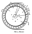
- FIG. 10 Referring to the prior art Cosmos expansible sleeve holder schematically illustrated in Fig 1, indicated gener strictlyally by reference numeral 10, there is shown an annular body 16 of vulcanized rubber, the only material specified by Cosmos, mounted on a flanged steel wheel rim 12 provided with through-passages 13 for mounting on a shaft to be rotated about the axis 14.
- Inner hoop 22 is secured by its inner surface to outer surface 24 of the rim 12.
- Outer hoop 18 of the annular body is spaced apart a distance D from the inner hoop by a thin, membranous web 32 and angulated planar ribs 26, each of which ribs extends axially between hoops 18 and 22 for their axial lengths (measured along the axial direction).
- the angulation of the ribs, angle A, is between 15° and 75°, with respect to the radial plane R, all the ribs being angulated in the same direction.
- the ribs 26 have a thickness d s measured in a direction perpendicular to its length (measured along the axis), and an end-to-end length L in the angular direction.
- the ribs and hoops are connected by a web 32 formed at the parting line of molds in which the wheel is molded, and therefore is positioned midway between the axial ends of the inner and outer hoops.
- the web 32 is formed as "flash" at the parting line of the mold, the web is a thin extensible rubber membrane, and because the ribs are angulated unidirectionally, the diameter of the wheel, and its outer radius r o , expands upon rotation, though the inner radius r i of the annular body does not, because it is secured to the wheel rim. Since the material of the annular body is vulcanized rubber and the ribs 26 are angulated in a common direction, the wheel has essentially no ability to carry a load supported on an axle to which the wheel rim 12 is bolted.
- the abrasive sleeve or belt 21 which will not slide off because of the centrifugal force generated when the wheel is rotated at high speeds.
- the hoop spacing that is, the distance between the inside surface of the outer hoop 18 and the outside surface of the inner hoop 22 is D.
- the outer surface 19 of the outer hoop 18 is concave when the wheel is at rest, though this dished surface is not shown.
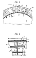
- FIG 2 there is shown an elevational view, with portions broken away, of a wheel indicated generally by 10′, including the TNPT 16′ of this invention, molded from polyurethane and mounted on wheel rim 12.
- first ribs 26′ referred to as a front set
- second ribs 30 which constitute a rear set, so referred to because the front and rear sets of ribs are integrally connected by the web 32′ having a thickness d w , which web also connects the outer and inner hoops 18′ and 22′ as in Fig 1.
- the term "integral” refers to the TNPT being formed as a whole, and the term “unitary” describes the interaction of the component structural elements as a unit.
- the hoop spacing is D′.
- the ribs 30 are of equal length L and oppositely directed to ribs 26, but at the same angle, for convenience in the molding of the TNPT, though both the lengths L and the angulation of the ribs may be different as long as they are oppositely directed.
- a front rib 26′ cross at least one rear rib 30, resulting in a "crossed" rib structure for optimum stiffness and load-carrying ability.
- the ribs 26′ having a thickness d s measured in a direction perpendicular to its length (measured along the axis), and an end-to-end length L in the angular direction, are preferably undercut at 34, as shown, where their ends meet the inner and outer hoops 22 and 18 respectively, to enhance flexibility of the connection, thus facilitating compression of the ribs 26′ and 30 without bending as each portion of the circumference of the TNPT contacts the ground while the vehicle on which the TNPT is mounted travels over the ground.
- the web 32′ is positioned midway between the axial ends of the inner and outer hoops 18′ an 22′, and connected at its (the web's) inner periphery 32c to the inner hoop 22, and at its outer periphery 32d to outer hoop 18, so that the edge of rib 26′ lies along one side face 32a of the web. All the first ribs 26′ (front set) are similarly connected, so that all ribs are angled at angle A in the same direction.
- all the second ribs 30 (rear set) are connected at their corresponding inner and outer ends to the inner and outer hoops and their edges lie along the face 32b of the web, so that all the ribs 26′ and 30 are angled at substantially equal angles A, but the first ribs are directed oppositely to the second ribs.
- the TNPT When the TNPT is to be used as a tire for an automob ile or truck, the TNPT is provided with a rubber tread 20 secured to the outer circumferential surface of the outer hoop 18.
- the stiffening function of the web 32 in combination with the crossed ribs is more clearly evident in Fig 3.
- the web tends to prevent the ribs from deforming by being bent along L, but allows compressive deformation of the TNPT in the area around the point of contact with the ground.
- the ribs prevent the web from buckling in the axial direction until P cr is reached, so that the web and crossed ribs cooperate to carry the load.
- Changing the angle A of the ribs effectively varies the spring rate without changing the dimensions of the structural components of the TNPT, or the composition of the elastomer from which it is molded.
- the ability of the TNPT to be deformed yet return to its cylindrical shape, essentially instantaneously, under compression and sudden transitions of loading, requires that the TNPT withstand a maximum strain of 20% during normal operation over several thousand miles, yet buckle locally to absorb the sudden impact of a projecting object, or road surface irregularity. It is this unexpected ability derived from its unique construction from the elastomer which gives the TNPT the handling and ride characteristics deemed essential in a conventional pneumatic tire.
- the particular design of the essential deformability and buckling characteristics of the TNPT which imbue it with the ability to mimic the ride and handling characteristics of a convention pneumatic tire, may be varied not only by changing the dimensions of the ribs and web, and the dimensions and relative disposition of the ribs, but also by varying the radius of the undercuts 34 which preferably range from 0.125" to 0.5" on the acute angle junctions of the ribs with the inner and outer hoops; and, from 0.25" to 1" on the obtuse angle junctions of the ribs with the inner and outer hoops. It is most preferred to undercut only one end of each rib only in the acute angles where that rib joins the inner hoop and outer hoops, though in the Figs the ribs are illustrated with undercuts also in the obtuse angles.
- An annular body of a TNPT for a luggage cart, fork lift, an automobile tire or spare tire, or insert for a pneumatic tire designed to have "run-flat” operation is formed with dimensions, dimensional relationships, and angular relationships which fall within the preferred ranges set forth in the following Table.
- TABLE 1 Item Preferred range r o 4" to 18" A 20° to 60° d i , d o 0.0312" to 0.5" D 1" to 4" r o /D 1 to 18 D/d w 10 to 2.5 L (value of L depends on the values chosen for A and D) L/d s 2 to 40 t i , t o 1.5" to 7" r i 2" to 16"
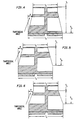
- Fig 3 illustrates a crossectional elevational view of a mounted TNPT
- Figs 4-6 illustrate crossectional elevational views unmounted TNPTs in each of which a web is positioned mid-way between the outer edges of the inner and outer hoops, respectively, so that the ribs are disposed symmetrically about the common circumferential center-line of the hoops, but the ribs on one side being oppositely directed relative to the ribs on the other.
- the central web is normal, that is perpendicular to both the inner and outer hoops.
- Fig 3 illustrates the ribs flaring continuously outwardly commencing at the inner hoop and terminating at the outer hoop.
- Figs 4-6 illustrate the ribs flaring outwardly, commencing to flare at different locations. In each of these embodiments flaring of the ribs does not commence and terminate at the inner and outer hoops of the TNPT.
- the precise geometry of the ribs may be tailored to provide desired buckling and cushioning, inter alia, which determine the 'ride' and 'handling' charcteristics of the TNPT.
- the ribs may be undercut if desired, and the undercuts may be provided at more than one location on each rib, so that the undercuts determine where the ribs buckle.
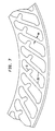
- Figs 7-8 illustrate an embodiment of the TNPT in which the ribs are provided with "bump-stops" on their lower surfaces, so that in normal operation, the bump-stops may or may not abut the next adjacent rib, depending upon the applied force. Where the force is sufficiently high to cause the bumpstop of one rib to be pressed against the next adjacent rib, as shown in Fig 8, the deflection of the ribs under severe buckling conditions is lessened.
- a portion of the TNPT is shown as it undergoes normal compressive deformation during operation of a vehicle over a smooth road surface.
- the loading force on the TNPT is approximately 800 lb (363 kg).
- the ribs 26′ and the crossed rib immediately behind rib 26′ most directly support the major portion of the load, and are under sufficient compression to decrease the overall lengths of the ribs.
- the unloaded ribs are each 2.12" (5.83 cm) long, while the loaded ribs are 1.99" (5.05 cm) long.
- the TNPT weighs less, and can be stored in a smaller space than a comparable conventional inflated pneumatic spare tire.
- the space and weight objectives for a compact spare tire are best met if the total material volume (space occupied by the material of the TNPT) divided by total projected volume (space between the outer surface of the outer hoop and the inner surface of the inner hoop) is between 20% and 60%.
- Another desirable characteristic of any tire is an overall spring rate which changes depending upon the type of surface against which the tire is loaded. Specifically, it is desirable that the spring rate be lower over a bump or article obstructing the path, than over a flat surface.
- the desirable ratio of spring rate over a flat surface divided by spring rate over a 0.5" (1.27 cm) thick cleat which spans the width of the tire is between 1.4 and 6.0, preferably between 2 and 4.
- the annular body 16′ may be adhered to the surface 24 of wheel rim 12 by being molded directly thereto in a conventional liquid molding process, with the outer surface 24 having been prepared in a known manner to receive and secure the elastomer used.
- the wheel rim 12 is provided with flanges 36 and 38 which cooperate with the mold to form the annular body 1′ on surface 24.
- Any conventional method for molding polyurethane may be used to form the TNPT, such as one described in aforementioned copending U.S. Serial No. 190,299 the disclosure of which is incorporated by reference thereto as if fully set forth herein.
- the following illustrative example 1 provides details of a molded polyurethane TNPT in which the tread is pre-positioned in the mold and adhesively secured to the TNPT.
- a TNPT was conventionally molded in a mold having an inner mold ring by filling the mold with a reaction mixture of (a) toluenediisocyanate-poly(tetramethyleneether glycol (M.W. about 2000) (TDI-PTMEG) prepolymer having a NCO number of 6.5, and (b) a methylene-bis-orthochloroaniline (MBOCA) curative the (a/b) weight ratio being 1/0.21.
- M.W. about 2000 toluenediisocyanate-poly(tetramethyleneether glycol (M.W. about 2000)
- MOCA methylene-bis-orthochloroaniline
- the liquid reaction mixture is poured into the mold with care being taken to ensure that all the air in the mold is displaced by the liquid.
- the TNPT formed has ribs which are undercut in the acute angle at the inner hoop, and in the corresponding obtuse angle on the other side of the rib where it meets the outer hoop.
- a rubber tire tread having a thickness of about 0.6" is then adhered to the outer surface of the outer hoop 18′ using a methyl 2-cyanoacrylate adhesive and the resulting tire is fitted and adhered to a steel rim 12 using a polyurethane adhesive cured with an organic isocyanate cura tive.
- the resulting tire and wheel assembly was used to replace a conventional passenger car tire and wheel assembly.
- a car equipped with this tire and wheel assembly was driven at speed up to 40 mph (64 km/hr) without deleteriously affecting control of the car and without damage to the TNPT.
- the TNPT has the following dimensions: r i 8.05" (20.45 cm) r o 10.5" (26.04 cm) A 45° d i , d o 0.2" ( 0.51 cm), and 0.14" (0.356 cm) D 1.9" (4.82 cm) r o /D 5.5 D/d w 9.5 L 2.2" (5.59 cm) L/d s 8.5 t i 2.0" (5.08 cm) t o 3.0" (7.62 cm), each
- TNPTs have varying tread widths, so that the ratio of the tread width to that of the inner hoop is in the range from 1.0 (for the RNPT) to 1.61. All tires have the same inside diameter of the inner hoop, and substantially the same mass.
- the cornering coefficient is a quantitative measure of "handling".
- the cornering coefficient is measured as the ratio of lateral force to radial force at the designated slip angle of either 1° or 4°.
- the stepped up speed (SUS) measurements are a measure of high speed endurance under conditions of severe heat buildup. Performance of the tire under SUS conditions is measured sequentially under constant load which is 92% of the tire's 100% load rating. The test is conducted by commencing at 50 mph for 2 hr. After 2 hr, the speed is raised to 75 mph; and thereafter, at increments of 0.5 hr, the speed is raised in increments of 5 mph, so that at 5 hr the speed is 100 mph.
- the stepped up load (SUL) measurements are a measure of load-carrying capability for long term endurance. Performance under SUL conditions is measured in the following steps, sequentially at constant speed of 50 mph for 4 hr at 85% load; for 6 hr at 90% load; for 24 hr at 100% load; then increasing in equal increments of 10% for equal 8 hr increments thereafter. TABLE 2 Tread width Cornering Coeff. SUS (hr) SUL (hr) Width ratio (ins) *s.a. 1° s.a.
- the cornering coefficient increases as ratio of (tread width/inner hoop width) increases, whether the slip angle is 1° or 4°.
- the unexpected increase of the cornering coefficient with increasing ratio is attributable to the stabilization of the outer hoop carrying the tread.
- the outer hoop As a RNPT negotiates a corner, the outer hoop is deflected laterally inboard, in turn resulting in the inboard deflection of the ribs.
- the inner ribs then lift the inboard portion of the tread surface off the road surface, leaving a diminished tread surface area in contact with the road, in turn, resulting in decreased road holding as the lateral acceleration increases.
- This phenomenon is schematically illustrated in a series of illustrations duplicating stop-action photographs taken from a recording on a 0.5" VHS video camera.
- the photographs were made with the video camera mounted on an automobile ("auto" for brevity) and aimed at the right front wheel as the auto was making a hard left hand turn at between 60-70mph.
- Fig 10 shows a TNPT having a tread width of 2.68 inches and an outer diameter 85% of a pneumatic tire used on the test automobile, mounted on the same auto, and driven in a straight ahead direction, that is, with the direction of wheel heading directly forward.
- the pneumatic tire may be deflected laterally sufficiently so that the sidewall is in contact with the road surface. This results in an exaggerated bulge in the sidewall due to transient increased loading which occurs at the same time as the deflection.
- Fig 11 shows a RNPT having a tread width of 2.68" in a hard cornering situation sufficient to have a pneumatic tire (had one been used) deflected laterally sufficiently so that its sidewall contacts the road surface.
- the deflection obtained is ⁇ , this being the distance of the top of the arc of the deformed TNPT, from the line of the direction of wheel heading, and this deflection is relatively large, the tread appearing to have been 'sucked' underneath and inboard the turning wheel.
- Fig 12 shows a TNPT having the same mass as the one shown in Fig 11, so that the ratio of tread width to inner hoop is 1.5, powered through the same turn in the road at the same speed as used for the conditions depicted in Fig 11.
- the lateral deflection ⁇ is relatively small compared to that obtained with an RNPT having the same mass.
- a trapezoidal angle ⁇ in the range from about 15° to about 25° is more preferred. Least detrimental to the durability of the TNPT is ⁇ in the range from 20° to 22°.
- a TNPT of equivalent mass as the RNPT has lower rolling resistance, improved wear, and reduced abrasion of the tread center during locked wheel skids.
- TNPT nonlinear TNPT
- off-road recovery is experienced when a tire is driven off the road surface onto the shoulder of the road, the surface of the shoulder being at a slightly lower elevation than the road surface.
- the security and ease with which the wayward tire is returned to the road surface is a measure of its off-road recovery.
- a TNPT exhibits improved off-road recovery compared to that exhibited by a RNPT because the outermost tread edge has a smaller vertical force of reaction directly over the edge, resulting in less steering input (or angle of incidence) to scale the step-off in the surfaces.
- Nibbling is a phenomenon which is experienced when a tire, without steering input, tends to follow a seam or groove which is parallel to the direction of travel, and a physical feature (defect) in an otherwise smooth road surface.
- the TNPT exhibits improved nibbling performance compared to that exhibited by a RNPT of equivalent mass. Due to the greater flexibility of the outer edges of the tread, the TNPT does not conform to a parallel seam or groove with the same determination as does the RNPT. Rather, the TNPT rides over the seam or groove with mini mal re-direction of the vehicle to maintain its path.
- the structure of the TNPT of our invention is unique in that it is deliberately designed to buckle under specified conditions to provide the characteristics essential to mimic a conventional pneumatic tire.
- This unique construction demands that the ribs be angulated and they be compressible, rather than bend under load.
- the resulting "open" structure not only provides the essential ride and handling characteristics but allows the TNPT to dissipate heat during operation.
- the foregoing characteristics are lacking in any logical combination of the teachings of prior art references, each of which is conceptually so different that combining their teachings simply magnifies not only their conceptual differences but also the interaction of the structural elements which produce them.
Landscapes
- Engineering & Computer Science (AREA)
- Mechanical Engineering (AREA)
- Tires In General (AREA)
- Shaping By String And By Release Of Stress In Plastics And The Like (AREA)
- Polyurethanes Or Polyureas (AREA)
- Packaging Of Annular Or Rod-Shaped Articles, Wearing Apparel, Cassettes, Or The Like (AREA)
- Fluid-Damping Devices (AREA)
- Processing And Handling Of Plastics And Other Materials For Molding In General (AREA)
Applications Claiming Priority (2)
| Application Number | Priority Date | Filing Date | Title |
|---|---|---|---|
| US354589 | 1989-05-22 | ||
| US07/354,589 US4921029A (en) | 1984-04-16 | 1989-05-22 | Trapezoidal non-pneumatic tire with supporting and cushioning members |
Publications (3)
| Publication Number | Publication Date |
|---|---|
| EP0399383A2 true EP0399383A2 (de) | 1990-11-28 |
| EP0399383A3 EP0399383A3 (de) | 1991-05-29 |
| EP0399383B1 EP0399383B1 (de) | 1995-02-22 |
Family
ID=23394036
Family Applications (1)
| Application Number | Title | Priority Date | Filing Date |
|---|---|---|---|
| EP90109401A Expired - Lifetime EP0399383B1 (de) | 1989-05-22 | 1990-05-18 | Vollreifen in Trapezform mit Stütz- und Federungselementen |
Country Status (12)
| Country | Link |
|---|---|
| EP (1) | EP0399383B1 (de) |
| JP (1) | JP2589399B2 (de) |
| KR (1) | KR0150776B1 (de) |
| CN (1) | CN1022614C (de) |
| AT (1) | ATE118736T1 (de) |
| AU (1) | AU632970B2 (de) |
| CA (1) | CA2011473C (de) |
| DE (1) | DE69017079T2 (de) |
| DK (1) | DK0399383T3 (de) |
| ES (1) | ES2068280T3 (de) |
| GR (1) | GR3015562T3 (de) |
| MX (1) | MX164423B (de) |
Cited By (12)
| Publication number | Priority date | Publication date | Assignee | Title |
|---|---|---|---|---|
| EP0681532A4 (de) * | 1993-11-29 | 1996-05-08 | Uniroyal Goodrich Licensing | Mehrzellen-kautschukreifen und verfahren zur herstellung. |
| US8056593B2 (en) | 2007-10-26 | 2011-11-15 | Chemtura Corporation | Non-pneumatic tire |
| US8061398B2 (en) | 2008-02-25 | 2011-11-22 | Chemtura Corporation | Non-pneumatic tire having angled tread groove wall |
| CN102350923A (zh) * | 2011-07-13 | 2012-02-15 | 深圳市道尔轮胎科技有限公司 | 一种不会爆胎的开式结构轮胎 |
| WO2012128892A1 (en) | 2011-03-18 | 2012-09-27 | Chemtura Corporation | Non- pneumatic tire with annular spoke reinforcement |
| RU2546360C1 (ru) * | 2014-03-03 | 2015-04-10 | Святослав Михайлович Сергеев | Колесо транспортного средства |
| US9139045B2 (en) | 2008-11-06 | 2015-09-22 | Chemtura Corporation | Multiple hardness non-pneumatic tire |
| EP2910387A4 (de) * | 2012-10-22 | 2016-06-29 | Bridgestone Corp | Luftloser reifen |
| US10744821B2 (en) | 2014-03-17 | 2020-08-18 | Bridgestone Corporation | Non-pneumatic tire |
| CN112428750A (zh) * | 2019-08-26 | 2021-03-02 | 通伊欧轮胎株式会社 | 非充气轮胎 |
| CN113696677A (zh) * | 2021-09-29 | 2021-11-26 | 芜湖集拓实心胎有限公司 | 一种超续航平衡车实心胎 |
| EP3888936A4 (de) * | 2018-11-30 | 2022-08-10 | Bridgestone Corporation | Luftreifen |
Families Citing this family (36)
| Publication number | Priority date | Publication date | Assignee | Title |
|---|---|---|---|---|
| US5265659A (en) * | 1992-03-18 | 1993-11-30 | Uniroyal Goodrich Licensing Services, Inc. | Non-pneumatic tire with ride-enhancing insert |
| US5223599A (en) * | 1992-04-10 | 1993-06-29 | Uniroyal Chemical Company, Inc. | Polyurethane elastomer and non-pneumatic tire fabricated therefrom |
| WO1998025773A1 (fr) * | 1996-12-10 | 1998-06-18 | Komatsu Ltd. | Construction de pneumatique |
| JP3789942B2 (ja) * | 1996-12-10 | 2006-06-28 | 株式会社小松製作所 | タイヤ構造 |
| US7174936B2 (en) * | 2003-12-22 | 2007-02-13 | Caterpillar Inc | Solid suspended work machine tire |
| JP4946011B2 (ja) * | 2005-11-17 | 2012-06-06 | 横浜ゴム株式会社 | 非空気式タイヤ |
| JP3923073B1 (ja) * | 2006-10-27 | 2007-05-30 | 横浜ゴム株式会社 | 非空気式タイヤ |
| USD602422S1 (en) | 2007-12-10 | 2009-10-20 | Chemtura Corporation | Tire |
| USD602852S1 (en) | 2007-10-26 | 2009-10-27 | Chemtura Corporation | Tire |
| CA2880963C (en) * | 2010-09-01 | 2016-04-12 | Michelin Recherche Et Technique S.A. | Spoke edge geometry for a non-pneumatic tire |
| JP5879089B2 (ja) * | 2011-10-20 | 2016-03-08 | 株式会社ブリヂストン | 非空気入りタイヤの製造方法 |
| JP6288928B2 (ja) * | 2013-03-26 | 2018-03-07 | 株式会社ブリヂストン | 非空気入りタイヤ |
| JP5938366B2 (ja) * | 2013-05-15 | 2016-06-22 | 株式会社ブリヂストン | 非空気入りタイヤ |
| US9962994B2 (en) * | 2013-05-22 | 2018-05-08 | Sumitomo Rubber Industries, Ltd. | Airless tire and method for manufacturing same |
| US20150020943A1 (en) * | 2013-07-22 | 2015-01-22 | Bridgestone Americas Tire Operations, Llc | Low-Metal Tire |
| JP2015209135A (ja) * | 2014-04-25 | 2015-11-24 | 株式会社をくだ屋技研 | 荷役作業車用車輪 |
| US20170120681A1 (en) * | 2014-06-16 | 2017-05-04 | Bridgestone Corporation | Tire |
| CN104890448B (zh) * | 2015-05-14 | 2017-01-18 | 深圳市道尔化工涂料有限公司 | 一种具有舒适弹性结构胎面的非充气轮胎 |
| CN105034698B (zh) * | 2015-05-22 | 2017-08-25 | 深圳市道尔轮胎科技有限公司 | 一种带有缓冲机构的不爆胎聚氨酯力车胎 |
| CN105034700B (zh) * | 2015-05-22 | 2017-08-11 | 深圳市道尔轮胎科技有限公司 | 一种不会爆胎的开槽式结构聚氨酯力车胎 |
| JP6630114B2 (ja) * | 2015-10-19 | 2020-01-15 | 株式会社ブリヂストン | 非空気入りタイヤ、金型および非空気入りタイヤの製造方法 |
| CN113147266A (zh) * | 2016-12-02 | 2021-07-23 | 深圳市金特安科技有限公司 | 开式结构轮胎 |
| CN107264187A (zh) * | 2017-06-05 | 2017-10-20 | 乐山市同源科技有限公司 | 支柱式免充气不爆汽车胎 |
| JP2019043503A (ja) * | 2017-09-07 | 2019-03-22 | Toyo Tire株式会社 | 非空気圧タイヤ |
| JP6989082B2 (ja) | 2017-12-14 | 2022-01-05 | ブリヂストン アメリカズ タイヤ オペレーションズ、 エルエルシー | マルチピースウェブを有する非空気圧式タイヤ |
| CN109941045A (zh) * | 2017-12-21 | 2019-06-28 | 北京橡胶工业研究设计院有限公司 | 一种免充气轮胎结构 |
| JP2021509928A (ja) * | 2018-01-05 | 2021-04-08 | コベストロ、ドイチュラント、アクチエンゲゼルシャフトCovestro Deutschland Ag | 非空気入りタイヤならびにその製造方法およびその使用 |
| CN109878272A (zh) * | 2019-03-15 | 2019-06-14 | 厦门连科工业有限公司 | 一种轮胎及其生产方法 |
| CN110641471B (zh) * | 2019-10-08 | 2023-10-27 | 中信戴卡股份有限公司 | 一种动态获取车辆的载荷的方法、装置、设备及存储介质 |
| CN110561978A (zh) * | 2019-10-11 | 2019-12-13 | 安徽世界村智能装备有限公司 | 一种高耐久免充气减震防颠轮胎 |
| US11772416B2 (en) * | 2020-10-06 | 2023-10-03 | The Goodyear Tire & Rubber Company | System for detection of non-pneumatic tire loading |
| CN112406412A (zh) * | 2020-11-17 | 2021-02-26 | 温州富成机械有限公司 | 加强型免充气轮胎及其生产方法 |
| JP7561026B2 (ja) * | 2020-12-28 | 2024-10-03 | Toyo Tire株式会社 | 非空気圧タイヤ及び非空気圧タイヤの製造方法 |
| EP4338981B1 (de) * | 2021-05-13 | 2026-04-08 | Bridgestone Corporation | Luftloser reifen |
| CN114259711A (zh) * | 2022-01-12 | 2022-04-01 | 徐敏 | 一种瑜伽轮 |
| JP2024014060A (ja) * | 2022-07-21 | 2024-02-01 | 日産自動車株式会社 | エアレスタイヤ |
Family Cites Families (5)
| Publication number | Priority date | Publication date | Assignee | Title |
|---|---|---|---|---|
| GB191323006A (en) * | 1913-10-11 | 1914-01-08 | Daniel Albert York | Improvements in Tires. |
| DE2460051A1 (de) * | 1974-12-19 | 1976-07-01 | Bayer Ag | Einteilige pannensichere reifen |
| US3980606A (en) * | 1975-02-24 | 1976-09-14 | The Firestone Tire & Rubber Company | Polyurethane elastomers having prolonged flex life and tires made therefrom |
| AU580294B2 (en) * | 1984-04-16 | 1989-01-12 | Uniroyal Goodrich Licensing Services, Inc. | Non-pneumatic tire with supporting and cushioning members |
| US4934425A (en) * | 1988-03-23 | 1990-06-19 | Uniroyal Chemical Company, Inc. | Non-pneumatic tire |
-
1990
- 1990-03-05 CA CA002011473A patent/CA2011473C/en not_active Expired - Lifetime
- 1990-03-12 AU AU51210/90A patent/AU632970B2/en not_active Ceased
- 1990-04-16 CN CN90102175A patent/CN1022614C/zh not_active Expired - Fee Related
- 1990-04-18 MX MX20348A patent/MX164423B/es unknown
- 1990-04-23 JP JP2105519A patent/JP2589399B2/ja not_active Expired - Lifetime
- 1990-05-18 ES ES90109401T patent/ES2068280T3/es not_active Expired - Lifetime
- 1990-05-18 AT AT90109401T patent/ATE118736T1/de not_active IP Right Cessation
- 1990-05-18 EP EP90109401A patent/EP0399383B1/de not_active Expired - Lifetime
- 1990-05-18 DK DK90109401.1T patent/DK0399383T3/da active
- 1990-05-18 DE DE69017079T patent/DE69017079T2/de not_active Expired - Fee Related
- 1990-05-22 KR KR1019900007318A patent/KR0150776B1/ko not_active Expired - Fee Related
-
1995
- 1995-03-30 GR GR940403224T patent/GR3015562T3/el unknown
Cited By (14)
| Publication number | Priority date | Publication date | Assignee | Title |
|---|---|---|---|---|
| EP0681532A4 (de) * | 1993-11-29 | 1996-05-08 | Uniroyal Goodrich Licensing | Mehrzellen-kautschukreifen und verfahren zur herstellung. |
| US8056593B2 (en) | 2007-10-26 | 2011-11-15 | Chemtura Corporation | Non-pneumatic tire |
| US8061398B2 (en) | 2008-02-25 | 2011-11-22 | Chemtura Corporation | Non-pneumatic tire having angled tread groove wall |
| US9139045B2 (en) | 2008-11-06 | 2015-09-22 | Chemtura Corporation | Multiple hardness non-pneumatic tire |
| WO2012128892A1 (en) | 2011-03-18 | 2012-09-27 | Chemtura Corporation | Non- pneumatic tire with annular spoke reinforcement |
| CN102350923A (zh) * | 2011-07-13 | 2012-02-15 | 深圳市道尔轮胎科技有限公司 | 一种不会爆胎的开式结构轮胎 |
| EP2910387A4 (de) * | 2012-10-22 | 2016-06-29 | Bridgestone Corp | Luftloser reifen |
| US9713940B2 (en) | 2012-10-22 | 2017-07-25 | Bridgestone Corporation | Non-pneumatic tire |
| RU2546360C1 (ru) * | 2014-03-03 | 2015-04-10 | Святослав Михайлович Сергеев | Колесо транспортного средства |
| US10744821B2 (en) | 2014-03-17 | 2020-08-18 | Bridgestone Corporation | Non-pneumatic tire |
| EP3888936A4 (de) * | 2018-11-30 | 2022-08-10 | Bridgestone Corporation | Luftreifen |
| US11766894B2 (en) | 2018-11-30 | 2023-09-26 | Bridgestone Corporation | Non-pneumatic tire |
| CN112428750A (zh) * | 2019-08-26 | 2021-03-02 | 通伊欧轮胎株式会社 | 非充气轮胎 |
| CN113696677A (zh) * | 2021-09-29 | 2021-11-26 | 芜湖集拓实心胎有限公司 | 一种超续航平衡车实心胎 |
Also Published As
| Publication number | Publication date |
|---|---|
| AU5121090A (en) | 1990-11-22 |
| KR0150776B1 (ko) | 1998-10-01 |
| JPH02310102A (ja) | 1990-12-25 |
| CA2011473C (en) | 1998-01-06 |
| ATE118736T1 (de) | 1995-03-15 |
| JP2589399B2 (ja) | 1997-03-12 |
| CA2011473A1 (en) | 1990-11-22 |
| MX164423B (es) | 1992-08-12 |
| ES2068280T3 (es) | 1995-04-16 |
| CN1022614C (zh) | 1993-11-03 |
| EP0399383B1 (de) | 1995-02-22 |
| DE69017079T2 (de) | 1995-06-14 |
| GR3015562T3 (en) | 1995-06-30 |
| AU632970B2 (en) | 1993-01-14 |
| CN1047476A (zh) | 1990-12-05 |
| EP0399383A3 (de) | 1991-05-29 |
| KR900017810A (ko) | 1990-12-20 |
| DK0399383T3 (da) | 1995-05-01 |
| DE69017079D1 (de) | 1995-03-30 |
Similar Documents
| Publication | Publication Date | Title |
|---|---|---|
| EP0399383B1 (de) | Vollreifen in Trapezform mit Stütz- und Federungselementen | |
| US4921029A (en) | Trapezoidal non-pneumatic tire with supporting and cushioning members | |
| EP0401564B1 (de) | Vollreifen mit Bienenwabenstruktur mit einer Einzel-Membran an einer Seite | |
| US4832098A (en) | Non-pneumatic tire with supporting and cushioning members | |
| US7650919B2 (en) | Non-pneumatic tire having web spokes | |
| US7143797B2 (en) | Airless tire | |
| US5265659A (en) | Non-pneumatic tire with ride-enhancing insert | |
| US5460213A (en) | Multiple non-pneumatic tire and process for making it | |
| US20020096237A1 (en) | Compliant rim and wheel and assembly | |
| EP1420964B1 (de) | Nicht- pneumatischer reifen | |
| EP0502353B1 (de) | Druckloser Reifen für Reserverad | |
| EP0353006B1 (de) | Elastischer Reifen | |
| CN1955018B (zh) | 一种结构支撑轮胎以及确定轮辐条横截面的方法 | |
| EP1607243B1 (de) | Geräuschreduzierendes System für Fahrzeugreifen | |
| US20120234444A1 (en) | Non-pneumatic tire with annular spoke reinforcing web | |
| US5174634A (en) | Non-pneumatic spare wheel and tire | |
| US5591282A (en) | Tire and vehicle system utilizing asymmetric support member molded to inboard sidewall | |
| US6443201B1 (en) | Pneumatic tire with extended load carrying capacity | |
| US7281553B1 (en) | Tire with compression-bearing hoop structure | |
| US20030155057A1 (en) | Asymmetric mold tread contour | |
| JPH04278806A (ja) | ラジアルタイヤ | |
| CN114590076A (zh) | 用于支撑结构的车轮 | |
| US20250303802A1 (en) | Toroidal insert comprising multiple segments for a run-flat tire assembly | |
| US20170355233A1 (en) | Tire with concave sidewalls | |
| US20220063354A1 (en) | Wheel-mounted run-flat tire insert and associated methods |
Legal Events
| Date | Code | Title | Description |
|---|---|---|---|
| PUAI | Public reference made under article 153(3) epc to a published international application that has entered the european phase |
Free format text: ORIGINAL CODE: 0009012 |
|
| AK | Designated contracting states |
Kind code of ref document: A2 Designated state(s): AT BE CH DE DK ES FR GB GR IT LI LU NL SE |
|
| PUAL | Search report despatched |
Free format text: ORIGINAL CODE: 0009013 |
|
| AK | Designated contracting states |
Kind code of ref document: A3 Designated state(s): AT BE CH DE DK ES FR GB GR IT LI LU NL SE |
|
| 17P | Request for examination filed |
Effective date: 19911003 |
|
| 17Q | First examination report despatched |
Effective date: 19930407 |
|
| RAP1 | Party data changed (applicant data changed or rights of an application transferred) |
Owner name: UNIROYAL GOODRICH LICENSING SERVICES, INC. |
|
| GRAA | (expected) grant |
Free format text: ORIGINAL CODE: 0009210 |
|
| ITF | It: translation for a ep patent filed | ||
| AK | Designated contracting states |
Kind code of ref document: B1 Designated state(s): AT BE CH DE DK ES FR GB GR IT LI LU NL SE |
|
| REF | Corresponds to: |
Ref document number: 118736 Country of ref document: AT Date of ref document: 19950315 Kind code of ref document: T |
|
| REF | Corresponds to: |
Ref document number: 69017079 Country of ref document: DE Date of ref document: 19950330 |
|
| REG | Reference to a national code |
Ref country code: ES Ref legal event code: FG2A Ref document number: 2068280 Country of ref document: ES Kind code of ref document: T3 |
|
| REG | Reference to a national code |
Ref country code: DK Ref legal event code: T3 |
|
| REG | Reference to a national code |
Ref country code: GR Ref legal event code: FG4A Free format text: 3015562 |
|
| ET | Fr: translation filed | ||
| PLBE | No opposition filed within time limit |
Free format text: ORIGINAL CODE: 0009261 |
|
| STAA | Information on the status of an ep patent application or granted ep patent |
Free format text: STATUS: NO OPPOSITION FILED WITHIN TIME LIMIT |
|
| 26N | No opposition filed | ||
| PGFP | Annual fee paid to national office [announced via postgrant information from national office to epo] |
Ref country code: SE Payment date: 19980420 Year of fee payment: 9 |
|
| PGFP | Annual fee paid to national office [announced via postgrant information from national office to epo] |
Ref country code: AT Payment date: 19980422 Year of fee payment: 9 Ref country code: DK Payment date: 19980422 Year of fee payment: 9 |
|
| PGFP | Annual fee paid to national office [announced via postgrant information from national office to epo] |
Ref country code: GR Payment date: 19980430 Year of fee payment: 9 Ref country code: NL Payment date: 19980430 Year of fee payment: 9 |
|
| PGFP | Annual fee paid to national office [announced via postgrant information from national office to epo] |
Ref country code: CH Payment date: 19980506 Year of fee payment: 9 |
|
| PGFP | Annual fee paid to national office [announced via postgrant information from national office to epo] |
Ref country code: BE Payment date: 19980513 Year of fee payment: 9 |
|
| PGFP | Annual fee paid to national office [announced via postgrant information from national office to epo] |
Ref country code: ES Payment date: 19980520 Year of fee payment: 9 |
|
| PGFP | Annual fee paid to national office [announced via postgrant information from national office to epo] |
Ref country code: LU Payment date: 19980526 Year of fee payment: 9 |
|
| PG25 | Lapsed in a contracting state [announced via postgrant information from national office to epo] |
Ref country code: AT Free format text: LAPSE BECAUSE OF NON-PAYMENT OF DUE FEES Effective date: 19990518 Ref country code: LU Free format text: LAPSE BECAUSE OF NON-PAYMENT OF DUE FEES Effective date: 19990518 |
|
| PG25 | Lapsed in a contracting state [announced via postgrant information from national office to epo] |
Ref country code: ES Free format text: LAPSE BECAUSE OF EXPIRATION OF PROTECTION Effective date: 19990519 Ref country code: SE Free format text: LAPSE BECAUSE OF NON-PAYMENT OF DUE FEES Effective date: 19990519 |
|
| PG25 | Lapsed in a contracting state [announced via postgrant information from national office to epo] |
Ref country code: LI Free format text: LAPSE BECAUSE OF NON-PAYMENT OF DUE FEES Effective date: 19990531 Ref country code: DK Free format text: LAPSE BECAUSE OF NON-PAYMENT OF DUE FEES Effective date: 19990531 Ref country code: CH Free format text: LAPSE BECAUSE OF NON-PAYMENT OF DUE FEES Effective date: 19990531 Ref country code: GR Free format text: LAPSE BECAUSE OF NON-PAYMENT OF DUE FEES Effective date: 19990531 Ref country code: BE Free format text: LAPSE BECAUSE OF NON-PAYMENT OF DUE FEES Effective date: 19990531 |
|
| BERE | Be: lapsed |
Owner name: UNIROYAL GOODRICH LICENSING SERVICES INC. Effective date: 19990531 |
|
| PG25 | Lapsed in a contracting state [announced via postgrant information from national office to epo] |
Ref country code: NL Free format text: LAPSE BECAUSE OF NON-PAYMENT OF DUE FEES Effective date: 19991201 |
|
| REG | Reference to a national code |
Ref country code: CH Ref legal event code: PL |
|
| EUG | Se: european patent has lapsed |
Ref document number: 90109401.1 |
|
| NLV4 | Nl: lapsed or anulled due to non-payment of the annual fee |
Effective date: 19991201 |
|
| REG | Reference to a national code |
Ref country code: DK Ref legal event code: EBP |
|
| REG | Reference to a national code |
Ref country code: ES Ref legal event code: FD2A Effective date: 20010601 |
|
| REG | Reference to a national code |
Ref country code: GB Ref legal event code: IF02 |
|
| REG | Reference to a national code |
Ref country code: GB Ref legal event code: 732E |
|
| PG25 | Lapsed in a contracting state [announced via postgrant information from national office to epo] |
Ref country code: IT Free format text: LAPSE BECAUSE OF NON-PAYMENT OF DUE FEES;WARNING: LAPSES OF ITALIAN PATENTS WITH EFFECTIVE DATE BEFORE 2007 MAY HAVE OCCURRED AT ANY TIME BEFORE 2007. THE CORRECT EFFECTIVE DATE MAY BE DIFFERENT FROM THE ONE RECORDED. Effective date: 20050518 |
|
| REG | Reference to a national code |
Ref country code: FR Ref legal event code: TP Ref country code: FR Ref legal event code: CD |
|
| PGFP | Annual fee paid to national office [announced via postgrant information from national office to epo] |
Ref country code: DE Payment date: 20080522 Year of fee payment: 19 |
|
| PGFP | Annual fee paid to national office [announced via postgrant information from national office to epo] |
Ref country code: GB Payment date: 20080521 Year of fee payment: 19 |
|
| GBPC | Gb: european patent ceased through non-payment of renewal fee |
Effective date: 20090518 |
|
| REG | Reference to a national code |
Ref country code: FR Ref legal event code: ST Effective date: 20100129 |
|
| PG25 | Lapsed in a contracting state [announced via postgrant information from national office to epo] |
Ref country code: FR Free format text: LAPSE BECAUSE OF NON-PAYMENT OF DUE FEES Effective date: 20090602 |
|
| PGFP | Annual fee paid to national office [announced via postgrant information from national office to epo] |
Ref country code: FR Payment date: 20080514 Year of fee payment: 19 |
|
| PG25 | Lapsed in a contracting state [announced via postgrant information from national office to epo] |
Ref country code: GB Free format text: LAPSE BECAUSE OF NON-PAYMENT OF DUE FEES Effective date: 20090518 |
|
| PG25 | Lapsed in a contracting state [announced via postgrant information from national office to epo] |
Ref country code: DE Free format text: LAPSE BECAUSE OF NON-PAYMENT OF DUE FEES Effective date: 20091201 |