EP0399462B1 - Verfahren zur Verbrennung von gebundenen Stickstoff enthaltendem Brennstoff - Google Patents
Verfahren zur Verbrennung von gebundenen Stickstoff enthaltendem Brennstoff Download PDFInfo
- Publication number
- EP0399462B1 EP0399462B1 EP90109694A EP90109694A EP0399462B1 EP 0399462 B1 EP0399462 B1 EP 0399462B1 EP 90109694 A EP90109694 A EP 90109694A EP 90109694 A EP90109694 A EP 90109694A EP 0399462 B1 EP0399462 B1 EP 0399462B1
- Authority
- EP
- European Patent Office
- Prior art keywords
- fuel
- oxidant
- stream
- injected
- combustion zone
- Prior art date
- Legal status (The legal status is an assumption and is not a legal conclusion. Google has not performed a legal analysis and makes no representation as to the accuracy of the status listed.)
- Expired - Lifetime
Links
- 239000000446 fuel Substances 0.000 title claims abstract description 92
- 238000000034 method Methods 0.000 title claims abstract description 32
- IJGRMHOSHXDMSA-UHFFFAOYSA-N Atomic nitrogen Chemical compound N#N IJGRMHOSHXDMSA-UHFFFAOYSA-N 0.000 title claims description 37
- 229910052757 nitrogen Inorganic materials 0.000 title claims description 19
- 239000007800 oxidant agent Substances 0.000 claims abstract description 75
- 230000001590 oxidative effect Effects 0.000 claims abstract description 75
- 238000002485 combustion reaction Methods 0.000 claims abstract description 62
- QVGXLLKOCUKJST-UHFFFAOYSA-N atomic oxygen Chemical compound [O] QVGXLLKOCUKJST-UHFFFAOYSA-N 0.000 claims description 25
- 239000001301 oxygen Substances 0.000 claims description 25
- 229910052760 oxygen Inorganic materials 0.000 claims description 25
- 239000007789 gas Substances 0.000 claims description 13
- 238000002347 injection Methods 0.000 claims description 9
- 239000007924 injection Substances 0.000 claims description 9
- 150000001875 compounds Chemical class 0.000 claims description 4
- MYMOFIZGZYHOMD-UHFFFAOYSA-N Dioxygen Chemical compound O=O MYMOFIZGZYHOMD-UHFFFAOYSA-N 0.000 claims description 3
- 125000000623 heterocyclic group Chemical group 0.000 claims description 2
- 125000003277 amino group Chemical group 0.000 claims 1
- 238000000889 atomisation Methods 0.000 claims 1
- MWUXSHHQAYIFBG-UHFFFAOYSA-N nitrogen oxide Inorganic materials O=[N] MWUXSHHQAYIFBG-UHFFFAOYSA-N 0.000 description 33
- 239000003921 oil Substances 0.000 description 6
- 239000000203 mixture Substances 0.000 description 4
- QGZKDVFQNNGYKY-UHFFFAOYSA-N Ammonia Chemical compound N QGZKDVFQNNGYKY-UHFFFAOYSA-N 0.000 description 2
- JUJWROOIHBZHMG-UHFFFAOYSA-N Pyridine Chemical compound C1=CC=NC=C1 JUJWROOIHBZHMG-UHFFFAOYSA-N 0.000 description 2
- 230000015572 biosynthetic process Effects 0.000 description 2
- 238000009841 combustion method Methods 0.000 description 2
- 230000000052 comparative effect Effects 0.000 description 2
- 230000000694 effects Effects 0.000 description 2
- LELOWRISYMNNSU-UHFFFAOYSA-N hydrogen cyanide Chemical compound N#C LELOWRISYMNNSU-UHFFFAOYSA-N 0.000 description 2
- 150000001412 amines Chemical class 0.000 description 1
- 229910021529 ammonia Inorganic materials 0.000 description 1
- 230000003111 delayed effect Effects 0.000 description 1
- 238000005516 engineering process Methods 0.000 description 1
- 238000010304 firing Methods 0.000 description 1
- 239000002737 fuel gas Substances 0.000 description 1
- 125000004433 nitrogen atom Chemical group N* 0.000 description 1
- 239000010747 number 6 fuel oil Substances 0.000 description 1
- UMJSCPRVCHMLSP-UHFFFAOYSA-N pyridine Natural products COC1=CC=CN=C1 UMJSCPRVCHMLSP-UHFFFAOYSA-N 0.000 description 1
Images
Classifications
-
- F—MECHANICAL ENGINEERING; LIGHTING; HEATING; WEAPONS; BLASTING
- F23—COMBUSTION APPARATUS; COMBUSTION PROCESSES
- F23C—METHODS OR APPARATUS FOR COMBUSTION USING FLUID FUEL OR SOLID FUEL SUSPENDED IN A CARRIER GAS OR AIR
- F23C7/00—Combustion apparatus characterised by arrangements for air supply
-
- Y—GENERAL TAGGING OF NEW TECHNOLOGICAL DEVELOPMENTS; GENERAL TAGGING OF CROSS-SECTIONAL TECHNOLOGIES SPANNING OVER SEVERAL SECTIONS OF THE IPC; TECHNICAL SUBJECTS COVERED BY FORMER USPC CROSS-REFERENCE ART COLLECTIONS [XRACs] AND DIGESTS
- Y02—TECHNOLOGIES OR APPLICATIONS FOR MITIGATION OR ADAPTATION AGAINST CLIMATE CHANGE
- Y02E—REDUCTION OF GREENHOUSE GAS [GHG] EMISSIONS, RELATED TO ENERGY GENERATION, TRANSMISSION OR DISTRIBUTION
- Y02E20/00—Combustion technologies with mitigation potential
- Y02E20/34—Indirect CO2mitigation, i.e. by acting on non CO2directly related matters of the process, e.g. pre-heating or heat recovery
Definitions
- This invention relates to post-mixed combustion wherein fuel and oxidant are injected separately into a combustion zone and thereafter mix and combust within the combustion zone.
- nitrogen which can lead to NO x formation, may come from sources exogenous to the fuel but mostly comes from the fuel itself. Accordingly methods designed to combust fuel for low NO x formation wherein nitrogen is present apart from the fuel, are generally not effective for the combustion of fuel containing bound nitrogen in order to achieve reduced NO x emissions.
- a method for combusting fuel containing bound nitrogen to achieve reduced NO x emissions comprising:
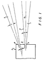
- Figure 1 is a simplified cross-sectional representation of one arrangement by which the method of this invention can be carried out.
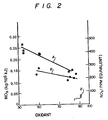
- Figure 2 is a graphical representation of NO x emissions from combustion carried out with the method of this invention and with combustion carried out with a known combustion method.
- bound nitrogen any chemical compound except for molecular nitrogen which contains at least one chemically bound nitrogen atom. Some simple examples of such compounds are ammonia, hydrogen cyanide and pyridine.
- Fuels containing bound nitrogen typically include oils and coals. In these fuels nitrogen is chemically bound in complex molecular forms and often incorporated in amines or heterocyclic rings. The fuel is injected into the combustion zone having a certain momentum which is the product of its mass and velocity. Generally the fuel is injected into the combustion zone at a velocity within the range of from 3 to 61 m (10 to 200 feet) per second.
- the stream expands in a roughly conical manner so that the periphery 4 of the fuel stream forms an angle ,a, with the axial centerline 5 of the fuel stream.
- This angle is generally within the range of from 5 to 10 degrees for a gaseous fuel stream from a straight round injector.
- Conical fuel flow deflectors are sometimes used to increase the angle of the spreading fuel stream.
- the angle of the atomized fuel droplets stream will vary depending on the design of the oil atomizer nozzle; typically this angle is within the range of from 5 to 30 degrees.
- Atomizing gas is often used in the oil atomizer to produce fine oil droplets. Air and steam are the most commonly used atomizing gases, while oxygen and fuel gases are sometimes used.
- the flowrate of oxygen contained in the atomizing gas must be less than 20 percent, and preferably less than 10 percent, of the flowrate of oxygen required for complete combustion of the fuel.
- a preferred oil atomizer is disclosed and claimed in U.S. Patent No. 4,738,614-Snyder, et al.
- Oxidant 7 is injected into combustion zone 2 from burner 3 spaced from the fuel injection point so that the fuel and oxidant are injected separately into the combustion zone and do not form a combustible mixture until after they are both within the combustion zone.
- the oxidant may be oxygen-enriched air or technically pure oxygen having an oxygen concentration exceeding 99.5 percent.
- the oxidant has an oxygen concentration exceeding 30 percent.
- the oxidant is injected at a velocity generally within the range of from 61 to 305 m (200 to 1000 feet) per second.
- the periphery of the oxidant stream forms an angle with the oxidant stream centerline This spreading angle is generally within the range of from 5 to 10 degrees.
- the oxidant is injected into the combustion zone in at least one stream and preferably in from 3 to 16 streams
- One particularly preferred arrangement has the fuel being injected into the combustion zone in a centrally located stream with the oxidant being injected into the combustion zone through a plurality of streams in a circle or ring around the centrally located fuel stream.
- the number of circularly oriented oxidant streams is within the range of from 3 to 16.
- the oxidant is injected into the combustion zone away from the fuel stream at an angle ,b, which is equal to or greater than the sum of the angles formed by the periphery of the fuel stream with the fuel stream axial centerline, i.e. angle a, and the spreading angle of the oxidant stream, shown in Figure 1 as angle c.
- angle b of the oxidant will be within the range of from 15 to 45 degrees.
- the oxidant is injected into the combustion zone with a total momentum, i.e. the sum of the momentums of each of the individual oxidant streams, which is at least equal to three times the momentum of the fuel.
- a total momentum i.e. the sum of the momentums of each of the individual oxidant streams, which is at least equal to three times the momentum of the fuel.
- the total oxidant momentum exceeds the fuel momentum by a factor within the range of from 10 to 30.
- at least 50 percent of the individual oxidant streams have a momentum which at least equals the fuel stream momentum and most preferably each individual oxidant stream has a momentum which at least equals the fuel stream momentum.
- the higher momentum of the oxidant streams establishes a bulk furnace gas circulation pattern whereby furnace gases and fuel are entrained into the oxidant streams due to the jet aspiration effects of the oxidant streams. Since the oxidant streams are injected away from the fuel stream and the momentum of the fuel stream is weaker than that of the oxidant streams, mixing of fuel with oxidant is delayed and controlled by the aspiration effects of the oxidant jets. Fuel is first mixed with hot furnace gases containing low levels of oxygen and combustion takes place with insufficient oxygen to complete the combustion. Combustion is completed as the fuel and the incomplete combustion products of the fuel rich combustion are entrained into the oxidant streams and additional oxygen is provided for complete combustion reactions.
- the high momentum and the high level of oxygen of the oxidant enable an injection angle which is significantly higher than conventional injection angles. This, along with the subsequent fuel entrainment into the oxidant, enables combustion with very low NO x generation while avoiding a blow off problem.
- Oxygen may also be introduced into the combustion zone in one or more straight streams or streams having an angle less than that defined above. In such a case at least 50 percent of the oxidant streams must be at the above-defined large divergent angles.
- a burner was fired at a firing rate of 166 kW (568,000 BTU/HR).
- the fuel was No. 6 fuel oil which contained about 0.54 weight percent bound nitrogen.
- the fuel was injected into the combustion zone from the burner at a rate of 14.4 kg (31.7 pounds) per hour with 4,2 standard m3/h (150 standard cubic feet per hour (SCFH)) of air as atomizing gas at a velocity of about 24 m (79 feet) per second and thus had a momentum of 1.3 Nm/s2 (0.94 lb-ft/sec2)
- the periphery of the fuel stream formed an angle of approximately 10 degrees with the fuel stream centerline. Oxidant containing 99.5 percent oxygen was injected into the combustion zone from the burner separately from the fuel injection.
- the oxidant was injected into the combustion zone in eight streams arranged in a circular pattern around the centrally located fuel stream at a total flowrate of 32 standard m3/h (1130 SCFH).
- the oxidant was injected at a velocity of about 187 m (614 feet) per second and thus the total oxidant momentum was 22 Nm/s2 (16.2 lb-ft/sec2) and each oxidant stream had a momentum of about 2.7 Nm/s2 (2 lb-ft/sec2).
- Each oxidant stream was injected into the combustion zone at an angle of 30 degrees away from the fuel stream. Taking into account the atomizing air, the oxygen concentration of the total oxidant provided to the combustion zone was about 90 percent.
- the method of this invention enables one to carry out combustion of fuel containing bound nitrogen while generating a significantly reduced level of NO x emissions over that possible when the method of this invention is not employed.
Landscapes
- Engineering & Computer Science (AREA)
- Chemical & Material Sciences (AREA)
- Combustion & Propulsion (AREA)
- Mechanical Engineering (AREA)
- General Engineering & Computer Science (AREA)
- Solid Fuels And Fuel-Associated Substances (AREA)
Claims (18)
- Verfahren zur Verbrennung von gebundenem Stickstoff enthaltendem Brennstoff zum Erreichen von verminderten NOx-Emissionen, bei dem:(A) in eine Verbrennungszone Brennstoff, der gebundenen Stickstoff enthält, in einem axial fließenden Strom eingeblasen wird,(B) in die Verbrennungszone Oxidationsmittel in mindestens einem Strom in Abstand von der Brennstoffeinblasstelle eingeblasen wird, wobei das Oxidationsmittel reinen Sauerstoff oder mit Sauerstoff angereicherte Luft aufweist und unter einem Winkel mit Bezug auf die axiale Mittellinie des Brennstoffstromes eingeblasen wird, der größer als die Summe der Ausbreitungswinkel eines einzelnen Oxidationsmittelstromes und des Brennstoffstromes ist, und wobei das Einblasen des Oxidationsmittels derart erfolgt, daß der gesamte Oxidationsmittelimpuls mindestens das Dreifache des Impulses des Brennstoffstromes beträgt; und(C) Brennstoff von dem Brennstoffstrom in den (die) Oxidationsmittelstrom (ströme) mitgerissen wird und der mitgerissene Brennstoff mit Oxidationsmittel verbrannt wird.
- Verfahren nach Anspruch 1, wobei der Brennstoff Öl ist.
- Verfahren nach Anspruch 1, wobei der Brennstoff in die Verbrennungszone mit einer Geschwindigkeit im Bereich von 3 bis 61 m (10 bis 200 Fuß) pro Sekunde eingeblasen wird.
- Verfahren nach Anspruch 1, wobei der Umfang des Brennstoffstromes mit der Mittellinie des Brennstoffstromes einen Winkel im Bereich von 5 bis 15 Grad bildet.
- Verfahren nach Anspruch 1, wobei das Oxidationsmittel eine Sauerstoffkonzentration von mehr als 30 Prozent hat.
- Verfahren nach Anspruch 1, wobei das Oxidationsmittel in die Verbrennungszone mit einer Geschwindigkeit im Bereich von 61 bis 305 m (200 bis 1000 Fuß) pro Sekunde eingeblasen wird.
- Verfahren nach Anspruch 1, wobei das Oxidationsmittel in die Verbrennungszone unter einem Winkel im Bereich von 15 bis 45 Grad eingeblasen wird.
- Verfahren nach Anspruch 1, wobei der Gesamtoxidationsmittelimpuls den Brennstoffimpuls um einen Faktor im Bereich von 3 bis 30 übertrifft.
- Verfahren nach Anspruch 1, wobei das Oxidationsmittel in die Verbrennungszone in Form von 3 bis 16 Strömen eingeblasen wird.
- Verfahren nach Anspruch 1, wobei der Brennstoff in die Verbrennungszone in einem zentral angeordneten Strom eingeblasen wird und das Oxidationsmittel in die Verbrennungszone in einer Mehrzahl von Strömen eingeblasen wird, die in einem Ring um den zentralen Brennstoffstrom herum angeordnet sind.
- Verfahren nach Anspruch 10, wobei die Anzahl der Oxidationsmittelströme im Bereich von 3 bis 16 liegt.
- Verfahren nach Anspruch 1, wobei mindestens ein Teil des gebundenen Stickstoffes des Brennstoffes in einer chemischen Verbindung enthalten ist, die einen heterozyklischen Ring aufweist.
- Verfahren nach Anspruch 1, wobei mindestens ein Teil des gebundenen Stickstoffes des Brennstoffes in einer chemischen Verbindung enthalten ist, die eine Amingruppe aufweist.
- Verfahren nach Anspruch 1, wobei der Brennstoffstrom in feine Tröpfchen zerstäubt wird.
- Verfahren nach Anspruch 14, wobei das Zerstäuben unter Anwendung eines Zerstäubungsgases durchgeführt wird.
- Verfahren nach Anspruch 15, wobei das Zerstäubungsgas Sauerstoff aufweist und der Sauerstoff, welcher der Verbrennungszone mit dem Zerstäubungsgas zugeführt wird, nicht mehr als 20 Prozent des Sauerstoffes beträgt, der für eine vollständige Verbrennung des Brennstoffes erforderlich ist.
- Verfahren nach Anspruch 1, bei dem mindestens 50 Prozent der einzelnen Oxidationsmittelströme einen Impuls haben, der mindestens gleich dem Impuls des Brennstoffstromes ist.
- Verfahren nach Anspruch 1, bei dem jeder einzelne Oxidationsmittelstrom einen Impuls hat, der mindestens gleich dem Impuls des Brennstoffstromes ist.
Priority Applications (1)
| Application Number | Priority Date | Filing Date | Title |
|---|---|---|---|
| AT90109694T ATE92172T1 (de) | 1989-05-23 | 1990-05-22 | Verfahren zur verbrennung von gebundenen stickstoff enthaltendem brennstoff. |
Applications Claiming Priority (2)
| Application Number | Priority Date | Filing Date | Title |
|---|---|---|---|
| US07/355,451 US4946382A (en) | 1989-05-23 | 1989-05-23 | Method for combusting fuel containing bound nitrogen |
| US355451 | 1989-05-23 |
Publications (3)
| Publication Number | Publication Date |
|---|---|
| EP0399462A2 EP0399462A2 (de) | 1990-11-28 |
| EP0399462A3 EP0399462A3 (de) | 1991-06-05 |
| EP0399462B1 true EP0399462B1 (de) | 1993-07-28 |
Family
ID=23397476
Family Applications (1)
| Application Number | Title | Priority Date | Filing Date |
|---|---|---|---|
| EP90109694A Expired - Lifetime EP0399462B1 (de) | 1989-05-23 | 1990-05-22 | Verfahren zur Verbrennung von gebundenen Stickstoff enthaltendem Brennstoff |
Country Status (10)
| Country | Link |
|---|---|
| US (1) | US4946382A (de) |
| EP (1) | EP0399462B1 (de) |
| JP (1) | JPH0765731B2 (de) |
| KR (1) | KR950013955B1 (de) |
| CN (1) | CN1023345C (de) |
| AT (1) | ATE92172T1 (de) |
| BR (1) | BR9002371A (de) |
| CA (1) | CA2017258C (de) |
| DE (1) | DE69002393T2 (de) |
| MX (1) | MX172404B (de) |
Families Citing this family (35)
| Publication number | Priority date | Publication date | Assignee | Title |
|---|---|---|---|---|
| US5242295A (en) * | 1991-02-11 | 1993-09-07 | Praxair Technology, Inc. | Combustion method for simultaneous control of nitrogen oxides and products of incomplete combustion |
| US5213492A (en) * | 1991-02-11 | 1993-05-25 | Praxair Technology, Inc. | Combustion method for simultaneous control of nitrogen oxides and products of incomplete combustion |
| US5076779A (en) * | 1991-04-12 | 1991-12-31 | Union Carbide Industrial Gases Technology Corporation | Segregated zoning combustion |
| US5209656A (en) * | 1991-08-29 | 1993-05-11 | Praxair Technology, Inc. | Combustion system for high velocity gas injection |
| US5266025A (en) * | 1992-05-27 | 1993-11-30 | Praxair Technology, Inc. | Composite lance |
| GB9314112D0 (en) * | 1993-07-08 | 1993-08-18 | Northern Eng Ind | Low nox air and fuel/air nozzle assembly |
| KR100234570B1 (ko) * | 1993-08-31 | 1999-12-15 | 조안 엠. 젤사 | 아르곤과 산소를 이용한 연소방법 |
| JP2942711B2 (ja) | 1993-11-17 | 1999-08-30 | プラクスエア・テクノロジー・インコーポレイテッド | 深段階的燃焼法 |
| US5387100A (en) * | 1994-02-17 | 1995-02-07 | Praxair Technology, Inc. | Super off-stoichiometric combustion method |
| US5458672A (en) * | 1994-06-06 | 1995-10-17 | Praxair Technology, Inc. | Combustion of sulfur released from sulfur bearing materials |
| BR9502777A (pt) * | 1994-06-13 | 1996-04-23 | Praxair Technology Inc | Equipamento e processo para a atomização de combustível líquido |
| US5601425A (en) * | 1994-06-13 | 1997-02-11 | Praxair Technology, Inc. | Staged combustion for reducing nitrogen oxides |
| US5772421A (en) * | 1995-05-26 | 1998-06-30 | Canadian Gas Research Institute | Low nox burner |
| FR2777068B1 (fr) * | 1998-04-02 | 2000-05-05 | Air Liquide | Procede de combustion par injections separees du combustible et du comburant |
| US6699030B2 (en) | 2001-01-11 | 2004-03-02 | Praxair Technology, Inc. | Combustion in a multiburner furnace with selective flow of oxygen |
| US20020127505A1 (en) | 2001-01-11 | 2002-09-12 | Hisashi Kobayashi | Oxygen enhanced low nox combustion |
| US6699031B2 (en) | 2001-01-11 | 2004-03-02 | Praxair Technology, Inc. | NOx reduction in combustion with concentrated coal streams and oxygen injection |
| US6699029B2 (en) | 2001-01-11 | 2004-03-02 | Praxair Technology, Inc. | Oxygen enhanced switching to combustion of lower rank fuels |
| US6702569B2 (en) | 2001-01-11 | 2004-03-09 | Praxair Technology, Inc. | Enhancing SNCR-aided combustion with oxygen addition |
| US6405664B1 (en) * | 2001-04-23 | 2002-06-18 | N-Viro International Corporation | Processes and systems for using biomineral by-products as a fuel and for NOx removal at coal burning power plants |
| US6883444B2 (en) * | 2001-04-23 | 2005-04-26 | N-Viro International Corporation | Processes and systems for using biomineral by-products as a fuel and for NOx removal at coal burning power plants |
| US6752849B2 (en) | 2001-08-08 | 2004-06-22 | N-Viro International Corporation | Method for disinfecting and stabilizing organic wastes with mineral by-products |
| US6752848B2 (en) | 2001-08-08 | 2004-06-22 | N-Viro International Corporation | Method for disinfecting and stabilizing organic wastes with mineral by-products |
| ES2566798T3 (es) * | 2002-05-15 | 2016-04-15 | Praxair Technology, Inc. | Combustión con bajas emisiones de NOx |
| CA2485570C (en) | 2002-05-15 | 2009-12-22 | Praxair Technology, Inc. | Combustion with reduced carbon in the ash |
| US20070048679A1 (en) * | 2003-01-29 | 2007-03-01 | Joshi Mahendra L | Fuel dilution for reducing NOx production |
| US20040175663A1 (en) * | 2003-03-06 | 2004-09-09 | M. Shannon Melton | Method for combusting fuel in a fired heater |
| US6910878B2 (en) * | 2003-06-19 | 2005-06-28 | Praxair Technology, Inc. | Oxy-fuel fired process heaters |
| CA2487146C (en) * | 2003-11-14 | 2009-01-20 | Air Products And Chemicals, Inc. | Fuel staging process for low nox operations |
| CN1294380C (zh) * | 2003-12-09 | 2007-01-10 | 财团法人工业技术研究院 | 一种燃烧器 |
| US20080096146A1 (en) * | 2006-10-24 | 2008-04-24 | Xianming Jimmy Li | Low NOx staged fuel injection burner for creating plug flow |
| FR2927327B1 (fr) * | 2008-02-08 | 2010-11-19 | Saint Gobain | Four verrier bas nox a haut transfert de chaleur |
| FR2968746B1 (fr) | 2010-12-08 | 2014-11-21 | Saint Gobain | Combustion a jets divergents de combustible |
| MX2014003946A (es) * | 2011-10-03 | 2014-05-14 | Saint Gobain Emballage | Combustor de emisiones reducidas. |
| US9272905B2 (en) | 2014-02-27 | 2016-03-01 | Honeywell International, Inc. | Method for optimizing down fired reforming furnaces |
Family Cites Families (9)
| Publication number | Priority date | Publication date | Assignee | Title |
|---|---|---|---|---|
| US2941587A (en) * | 1955-07-14 | 1960-06-21 | Pan American Petroleum Corp | Combustion chamber burner |
| US4050879A (en) * | 1974-11-18 | 1977-09-27 | Mitsubishi Jukogyo Kabushiki Kaisha | Fuel combustion apparatus |
| JPS5819929B2 (ja) * | 1978-07-11 | 1983-04-20 | 新日本製鐵株式会社 | 低NO↓xバ−ナ− |
| JPS6026922B2 (ja) * | 1980-02-25 | 1985-06-26 | 川崎重工業株式会社 | 微粉炭バ−ナ |
| US4541796A (en) * | 1980-04-10 | 1985-09-17 | Union Carbide Corporation | Oxygen aspirator burner for firing a furnace |
| US4378205A (en) * | 1980-04-10 | 1983-03-29 | Union Carbide Corporation | Oxygen aspirator burner and process for firing a furnace |
| DE3331989A1 (de) * | 1983-09-05 | 1985-04-04 | L. & C. Steinmüller GmbH, 5270 Gummersbach | Verfahren zur verminderung der no(pfeil abwaerts)x(pfeil abwaerts)-emission bei der verbrennung von stickstoffhaltigen brennstoffen |
| US4765258A (en) * | 1984-05-21 | 1988-08-23 | Coal Tech Corp. | Method of optimizing combustion and the capture of pollutants during coal combustion in a cyclone combustor |
| JP2683545B2 (ja) * | 1988-05-25 | 1997-12-03 | 東京瓦斯 株式会社 | 炉内燃焼方法 |
-
1989
- 1989-05-23 US US07/355,451 patent/US4946382A/en not_active Expired - Lifetime
-
1990
- 1990-05-21 BR BR909002371A patent/BR9002371A/pt not_active IP Right Cessation
- 1990-05-22 DE DE90109694T patent/DE69002393T2/de not_active Expired - Fee Related
- 1990-05-22 MX MX020834A patent/MX172404B/es unknown
- 1990-05-22 CN CN90104392A patent/CN1023345C/zh not_active Expired - Fee Related
- 1990-05-22 KR KR1019900007317A patent/KR950013955B1/ko not_active Expired - Fee Related
- 1990-05-22 EP EP90109694A patent/EP0399462B1/de not_active Expired - Lifetime
- 1990-05-22 JP JP2130422A patent/JPH0765731B2/ja not_active Expired - Lifetime
- 1990-05-22 CA CA002017258A patent/CA2017258C/en not_active Expired - Fee Related
- 1990-05-22 AT AT90109694T patent/ATE92172T1/de not_active IP Right Cessation
Also Published As
| Publication number | Publication date |
|---|---|
| CA2017258A1 (en) | 1990-11-23 |
| MX172404B (es) | 1993-12-15 |
| EP0399462A3 (de) | 1991-06-05 |
| JPH0331604A (ja) | 1991-02-12 |
| EP0399462A2 (de) | 1990-11-28 |
| DE69002393T2 (de) | 1993-11-18 |
| US4946382A (en) | 1990-08-07 |
| KR950013955B1 (ko) | 1995-11-18 |
| ATE92172T1 (de) | 1993-08-15 |
| CN1023345C (zh) | 1993-12-29 |
| CA2017258C (en) | 1995-06-20 |
| KR900018595A (ko) | 1990-12-22 |
| DE69002393D1 (de) | 1993-09-02 |
| JPH0765731B2 (ja) | 1995-07-19 |
| CN1048590A (zh) | 1991-01-16 |
| BR9002371A (pt) | 1991-08-06 |
Similar Documents
| Publication | Publication Date | Title |
|---|---|---|
| US4946382A (en) | Method for combusting fuel containing bound nitrogen | |
| EP0397088B1 (de) | Verfahren und Vorrichtung zur Verbrennung mit oxidierendem Mehrfachstrahl | |
| CN1171032C (zh) | 减少氮氧化物生成的分阶段燃烧 | |
| US5076779A (en) | Segregated zoning combustion | |
| CA2485934C (en) | Low nox combustion | |
| EP0260382B2 (de) | Brenner zur NOx-armen Verbrennung | |
| EP1504219B1 (de) | Verbrennung mit vermindertem kohlenstoff in der asche | |
| US6394790B1 (en) | Method for deeply staged combustion | |
| EP1416221A1 (de) | Verbrennung von Konzentrierten Kohlenströmen bei Gleichzeitiger NOx-Reduzierung | |
| JPH0611117A (ja) | 予備混合した高速燃料噴流の低NOxバーナ | |
| US6865994B2 (en) | Step-diffuser for overfire air and overfire air/N-agent injector systems | |
| US5181475A (en) | Apparatus and process for control of nitric oxide emissions from combustion devices using vortex rings and the like | |
| AU2004205796A1 (en) | Process and apparatus for oxygen enrichment in fuel conveying gases | |
| CN101910724A (zh) | 燃烧器和用于实施氧燃烧的方法 | |
| JPH0227307Y2 (de) | ||
| SU1753186A1 (ru) | Способ сжигани пылеугольного топлива | |
| JPS62158906A (ja) | 石炭・水スラリ−用低NO↓x燃焼バ−ナ | |
| JPH05332510A (ja) | ボイラ等の低NOx燃焼方法及びその装置 |
Legal Events
| Date | Code | Title | Description |
|---|---|---|---|
| PUAI | Public reference made under article 153(3) epc to a published international application that has entered the european phase |
Free format text: ORIGINAL CODE: 0009012 |
|
| AK | Designated contracting states |
Kind code of ref document: A2 Designated state(s): AT BE DE FR GB IT NL |
|
| 17P | Request for examination filed |
Effective date: 19901231 |
|
| PUAL | Search report despatched |
Free format text: ORIGINAL CODE: 0009013 |
|
| AK | Designated contracting states |
Kind code of ref document: A3 Designated state(s): AT BE DE FR GB IT NL |
|
| 17Q | First examination report despatched |
Effective date: 19920325 |
|
| RAP1 | Party data changed (applicant data changed or rights of an application transferred) |
Owner name: PRAXAIR TECHNOLOGY, INC. |
|
| GRAA | (expected) grant |
Free format text: ORIGINAL CODE: 0009210 |
|
| AK | Designated contracting states |
Kind code of ref document: B1 Designated state(s): AT BE DE FR GB IT NL |
|
| ITF | It: translation for a ep patent filed | ||
| REF | Corresponds to: |
Ref document number: 92172 Country of ref document: AT Date of ref document: 19930815 Kind code of ref document: T |
|
| REF | Corresponds to: |
Ref document number: 69002393 Country of ref document: DE Date of ref document: 19930902 |
|
| ET | Fr: translation filed | ||
| PLBE | No opposition filed within time limit |
Free format text: ORIGINAL CODE: 0009261 |
|
| STAA | Information on the status of an ep patent application or granted ep patent |
Free format text: STATUS: NO OPPOSITION FILED WITHIN TIME LIMIT |
|
| 26N | No opposition filed | ||
| PGFP | Annual fee paid to national office [announced via postgrant information from national office to epo] |
Ref country code: FR Payment date: 19990430 Year of fee payment: 10 |
|
| PGFP | Annual fee paid to national office [announced via postgrant information from national office to epo] |
Ref country code: DE Payment date: 19990503 Year of fee payment: 10 Ref country code: AT Payment date: 19990503 Year of fee payment: 10 |
|
| PGFP | Annual fee paid to national office [announced via postgrant information from national office to epo] |
Ref country code: GB Payment date: 19990504 Year of fee payment: 10 |
|
| PGFP | Annual fee paid to national office [announced via postgrant information from national office to epo] |
Ref country code: NL Payment date: 19990510 Year of fee payment: 10 |
|
| PGFP | Annual fee paid to national office [announced via postgrant information from national office to epo] |
Ref country code: BE Payment date: 19990517 Year of fee payment: 10 |
|
| PG25 | Lapsed in a contracting state [announced via postgrant information from national office to epo] |
Ref country code: GB Free format text: LAPSE BECAUSE OF NON-PAYMENT OF DUE FEES Effective date: 20000522 Ref country code: AT Free format text: LAPSE BECAUSE OF NON-PAYMENT OF DUE FEES Effective date: 20000522 |
|
| PG25 | Lapsed in a contracting state [announced via postgrant information from national office to epo] |
Ref country code: BE Free format text: LAPSE BECAUSE OF NON-PAYMENT OF DUE FEES Effective date: 20000531 |
|
| BERE | Be: lapsed |
Owner name: PRAXAIR TECHNOLOGY INC. Effective date: 20000531 |
|
| PG25 | Lapsed in a contracting state [announced via postgrant information from national office to epo] |
Ref country code: NL Free format text: LAPSE BECAUSE OF NON-PAYMENT OF DUE FEES Effective date: 20001201 |
|
| GBPC | Gb: european patent ceased through non-payment of renewal fee |
Effective date: 20000522 |
|
| PG25 | Lapsed in a contracting state [announced via postgrant information from national office to epo] |
Ref country code: FR Free format text: LAPSE BECAUSE OF NON-PAYMENT OF DUE FEES Effective date: 20010131 |
|
| NLV4 | Nl: lapsed or anulled due to non-payment of the annual fee |
Effective date: 20001201 |
|
| PG25 | Lapsed in a contracting state [announced via postgrant information from national office to epo] |
Ref country code: DE Free format text: LAPSE BECAUSE OF NON-PAYMENT OF DUE FEES Effective date: 20010301 |
|
| REG | Reference to a national code |
Ref country code: FR Ref legal event code: ST |
|
| PG25 | Lapsed in a contracting state [announced via postgrant information from national office to epo] |
Ref country code: IT Free format text: LAPSE BECAUSE OF NON-PAYMENT OF DUE FEES;WARNING: LAPSES OF ITALIAN PATENTS WITH EFFECTIVE DATE BEFORE 2007 MAY HAVE OCCURRED AT ANY TIME BEFORE 2007. THE CORRECT EFFECTIVE DATE MAY BE DIFFERENT FROM THE ONE RECORDED. Effective date: 20050522 |