EP0399500B1 - Appareil de formation d'images - Google Patents
Appareil de formation d'images Download PDFInfo
- Publication number
- EP0399500B1 EP0399500B1 EP90109811A EP90109811A EP0399500B1 EP 0399500 B1 EP0399500 B1 EP 0399500B1 EP 90109811 A EP90109811 A EP 90109811A EP 90109811 A EP90109811 A EP 90109811A EP 0399500 B1 EP0399500 B1 EP 0399500B1
- Authority
- EP
- European Patent Office
- Prior art keywords
- forming apparatus
- image forming
- ribs
- charge removing
- substrate
- Prior art date
- Legal status (The legal status is an assumption and is not a legal conclusion. Google has not performed a legal analysis and makes no representation as to the accuracy of the status listed.)
- Expired - Lifetime
Links
- 239000002216 antistatic agent Substances 0.000 claims description 20
- 239000000758 substrate Substances 0.000 claims description 15
- 238000007599 discharging Methods 0.000 claims description 12
- 239000011810 insulating material Substances 0.000 claims description 11
- 239000004020 conductor Substances 0.000 claims description 10
- 238000011144 upstream manufacturing Methods 0.000 claims description 10
- 230000001105 regulatory effect Effects 0.000 claims description 5
- 239000011347 resin Substances 0.000 claims description 3
- 229920005989 resin Polymers 0.000 claims description 3
- 230000007423 decrease Effects 0.000 claims description 2
- 239000007787 solid Substances 0.000 claims 1
- 239000000463 material Substances 0.000 description 67
- 238000002474 experimental method Methods 0.000 description 3
- XEEYBQQBJWHFJM-UHFFFAOYSA-N Iron Chemical compound [Fe] XEEYBQQBJWHFJM-UHFFFAOYSA-N 0.000 description 2
- XLOMVQKBTHCTTD-UHFFFAOYSA-N Zinc monoxide Chemical compound [Zn]=O XLOMVQKBTHCTTD-UHFFFAOYSA-N 0.000 description 2
- 150000003242 quaternary ammonium salts Chemical class 0.000 description 2
- 239000000126 substance Substances 0.000 description 2
- GWEVSGVZZGPLCZ-UHFFFAOYSA-N Titan oxide Chemical compound O=[Ti]=O GWEVSGVZZGPLCZ-UHFFFAOYSA-N 0.000 description 1
- RTAQQCXQSZGOHL-UHFFFAOYSA-N Titanium Chemical compound [Ti] RTAQQCXQSZGOHL-UHFFFAOYSA-N 0.000 description 1
- 150000008055 alkyl aryl sulfonates Chemical class 0.000 description 1
- 150000008052 alkyl sulfonates Chemical class 0.000 description 1
- 230000001934 delay Effects 0.000 description 1
- 238000009413 insulation Methods 0.000 description 1
- 229910000765 intermetallic Inorganic materials 0.000 description 1
- 229910052742 iron Inorganic materials 0.000 description 1
- CPLXHLVBOLITMK-UHFFFAOYSA-N magnesium oxide Inorganic materials [Mg]=O CPLXHLVBOLITMK-UHFFFAOYSA-N 0.000 description 1
- 239000000395 magnesium oxide Substances 0.000 description 1
- AXZKOIWUVFPNLO-UHFFFAOYSA-N magnesium;oxygen(2-) Chemical compound [O-2].[Mg+2] AXZKOIWUVFPNLO-UHFFFAOYSA-N 0.000 description 1
- 229910044991 metal oxide Inorganic materials 0.000 description 1
- 238000000034 method Methods 0.000 description 1
- 238000012986 modification Methods 0.000 description 1
- 230000004048 modification Effects 0.000 description 1
- 230000002093 peripheral effect Effects 0.000 description 1
- 229920000515 polycarbonate Polymers 0.000 description 1
- 239000004417 polycarbonate Substances 0.000 description 1
- 238000007789 sealing Methods 0.000 description 1
- 230000035939 shock Effects 0.000 description 1
- 150000005846 sugar alcohols Polymers 0.000 description 1
- XOLBLPGZBRYERU-UHFFFAOYSA-N tin dioxide Chemical compound O=[Sn]=O XOLBLPGZBRYERU-UHFFFAOYSA-N 0.000 description 1
- 229910001887 tin oxide Inorganic materials 0.000 description 1
- 239000010936 titanium Substances 0.000 description 1
- 229910052719 titanium Inorganic materials 0.000 description 1
- OGIDPMRJRNCKJF-UHFFFAOYSA-N titanium oxide Inorganic materials [Ti]=O OGIDPMRJRNCKJF-UHFFFAOYSA-N 0.000 description 1
- 239000011787 zinc oxide Substances 0.000 description 1
Images




Classifications
-
- G—PHYSICS
- G03—PHOTOGRAPHY; CINEMATOGRAPHY; ANALOGOUS TECHNIQUES USING WAVES OTHER THAN OPTICAL WAVES; ELECTROGRAPHY; HOLOGRAPHY
- G03G—ELECTROGRAPHY; ELECTROPHOTOGRAPHY; MAGNETOGRAPHY
- G03G21/00—Arrangements not provided for by groups G03G13/00 - G03G19/00, e.g. cleaning, elimination of residual charge
-
- G—PHYSICS
- G03—PHOTOGRAPHY; CINEMATOGRAPHY; ANALOGOUS TECHNIQUES USING WAVES OTHER THAN OPTICAL WAVES; ELECTROGRAPHY; HOLOGRAPHY
- G03G—ELECTROGRAPHY; ELECTROPHOTOGRAPHY; MAGNETOGRAPHY
- G03G15/00—Apparatus for electrographic processes using a charge pattern
- G03G15/65—Apparatus which relate to the handling of copy material
- G03G15/6532—Removing a copy sheet form a xerographic drum, band or plate
-
- G—PHYSICS
- G03—PHOTOGRAPHY; CINEMATOGRAPHY; ANALOGOUS TECHNIQUES USING WAVES OTHER THAN OPTICAL WAVES; ELECTROGRAPHY; HOLOGRAPHY
- G03G—ELECTROGRAPHY; ELECTROPHOTOGRAPHY; MAGNETOGRAPHY
- G03G15/00—Apparatus for electrographic processes using a charge pattern
- G03G15/14—Apparatus for electrographic processes using a charge pattern for transferring a pattern to a second base
- G03G15/16—Apparatus for electrographic processes using a charge pattern for transferring a pattern to a second base of a toner pattern, e.g. a powder pattern, e.g. magnetic transfer
-
- G—PHYSICS
- G03—PHOTOGRAPHY; CINEMATOGRAPHY; ANALOGOUS TECHNIQUES USING WAVES OTHER THAN OPTICAL WAVES; ELECTROGRAPHY; HOLOGRAPHY
- G03G—ELECTROGRAPHY; ELECTROPHOTOGRAPHY; MAGNETOGRAPHY
- G03G15/00—Apparatus for electrographic processes using a charge pattern
- G03G15/14—Apparatus for electrographic processes using a charge pattern for transferring a pattern to a second base
- G03G15/16—Apparatus for electrographic processes using a charge pattern for transferring a pattern to a second base of a toner pattern, e.g. a powder pattern, e.g. magnetic transfer
- G03G15/163—Apparatus for electrographic processes using a charge pattern for transferring a pattern to a second base of a toner pattern, e.g. a powder pattern, e.g. magnetic transfer using the force produced by an electrostatic transfer field formed between the second base and the electrographic recording member, e.g. transfer through an air gap
- G03G15/1635—Apparatus for electrographic processes using a charge pattern for transferring a pattern to a second base of a toner pattern, e.g. a powder pattern, e.g. magnetic transfer using the force produced by an electrostatic transfer field formed between the second base and the electrographic recording member, e.g. transfer through an air gap the field being produced by laying down an electrostatic charge behind the base or the recording member, e.g. by a corona device
- G03G15/165—Arrangements for supporting or transporting the second base in the transfer area, e.g. guides
Definitions
- the present invention relates to an image forming apparatus such as an electrophotographic copying machine, a laser printer, an electrophotographic facsimile or that like, more particularly, to an image forming apparatus provided with a guiding member which is disposed on a downstream side of a transferring device in a feed direction.
- JP-A-58-14170 discloses a preventing member for preventing transfer paper from entering a transfer corotron. Guiding members are fitted on a destaticizing corotron, the guiding member extending partially into the area above the transfer corotron.
- JP-A-1-26878 discloses an electrostatic transfer device by which an insulating member is disposed between a transfer means and a charge removal means. Guide members are provided above the charge removal means, extensions of which extend into the opening of the transferring means.
- the United States Patent 4,579,441 discloses a detacking apparatus for use in an image forming apparatus in which destaticizing means are disposed downstream of a transfer corotron.
- the destaticizing means comprise guiding elements or ribs with a destaticizing brush located therebetween.
- separating device such as a separating discharger for separating a receiving substrate such as a sheet material from an image bearing member after transfer.
- the device may be provided with a separating belt, but no image can be formed at a portion where the separating belt is positioned, so that the copy produced lacks a part of image which is not desirable.
- the image bearing member such as a photosensitive drum gets small, the sheet material can be detached from the photosensitive drum without any particular separating devices. In other words, if the photosensitive drum has a relatively high curvature, the sheet material is detached from the photosensitive drum by virtue of its stiffness and its own weight.
- a conductive material is provided in close vicinity of the transferring device such as a transfer dis-charger, charges from the transfer discharger flow as an electric current through the conductive material to ground, which also causes inferior transfer due to lack of charges for transfer. Even if the conductive material is disposed so that the sheet material may come into contact with the conductive material after detachment from the photosensitive drum, the charges on the rear surface of the sheet material flow as an electric current through the conductive material rapidly, which causes crumbling of the toner image on the sheet material due to the shock.
- An image forming apparatus is disclosed in Japanese Patent Laid-Open Publication No. 126571/1984.
- This image forming apparatus comprises a transfer discharger, an insulating member and a charge removing member which are provided in this order in a sheet feed direction.
- the charge removing member is provided for removing the charges on the rear surface of the sheet material, after the sheet material is detached from the photosensitive drum by virtue of its stiffness and its own weight.
- the insulating member is provided between the transfer discharger and the charge removing member so that the charges from the transfer discharger may not flow as an electric current to the charge removing member.
- the conventional apparatus has a following problem. Even if the charge removing member is useful for removing the charges from the rear surface of the sheet material as described hereinabove, the insulating member is provided on the upstream side of the charge removing member, which diminishes the charge removing action of the charge removing member and delays timing or speed of the charge removing.
- the area on which the charge removing action is performed by the charge removing member is not limited to an outer edge of the charge removing member, but-extends over the circumference.
- the insulating member disposed on the upstream side of the charge removing member cuts off the charge removing action.
- the receiving substrate is not a plain paper but a sheet used for an Over Head Projector (OHP)
- OHP sheet Over Head Projector
- the insulating member holds many electrostatic charges which come from the transfer discharger and are generated as sheet material moves many times.
- the electrostatic charges on the insulating member used as a guiding member causes not only poor conveyance of the sheet material but also adhesion of toner material.
- the poor conveyance of the sheet material causes crumbling of toner image on the downstream part of the sheet material which is detached from the photosensitive material, and also causes inferior transfer on the upstream part of the sheet material onto which the toner image on the photosensitive drum is being transferred, and further causes a sheet jam.
- the toner-adhesion causes stains of the sheet material which is conveyed on the insulating member used as a guiding member. More particularly, if the transfer discharger is the type in which a part of an opening of the transfer discharger is covered with a part of the guiding member, the problem is more serious. That is, the guiding member covers the part of the discharger's opening in order to regulate a breadth of discharging area and to prevent a tip of the sheet material from entering the inside of the transfer discharger, but the guiding member is charged by the transfer discharger because of its insulation.
- the guiding member covering the part of said opening is made of insulating material in order to prevent the inferior transfer due to an electric current flow.
- the charged guiding member attracts floating toners scattered in the neighbourhood of the photosensitive drum. Since the toner adheres to the surface of the guiding member the tip and the rear surface of the sheet becomes dirty when the sheet material is guided by the guiding member.
- an image forming apparatus is provided as defined in claim 1.
- FIG. 1 is a sectional view showing a schematic configuration of a first embodiment of this invention incorporated in an image forming apparatus.
- the image forming apparatus comprises a photosensitive drum 1 used for an image bearing member.
- the photosensitive drum 1 rotates in a direction shown by arrow R in Figure 1 at a constant speed.
- An electrostatic latent image formed on a surface of the drum 1 is developed by a developing device (not shown) and converted into a toner image.
- a sheet material used as a receiving substrate such as a plain paper, an OHP sheet or that like, is fed as shown by arrow S in synchronism with the rotation of the photosensitive drum 1.
- a transfer discharger 5 used for a transferring means is disposed facing the photosensitive drum 1.
- On the upstream side of the transfer discharger 5 in the feed direction are disposed guiding members 2, 3 and a roller 4.
- the sheet material guided by the guiding members 2, 3 is fed to the surface of the photosensitive drum 1 by the roller 4 and comes into contact with the drum 1.
- the transfer discharger 5 comprises a discharging wire 6 and a U-shaped case 5A which is made of an electric conductor such as iron and surrounds the wire 6.
- the transfer discharger 5 has an opening 5B facing the photosensitive drum 1.
- An upstream part of the opening 5B is covered with a discharging breadth regulating member 10 made of insulating material.
- a downstream part of the opening 5B is covered with an upstream portion of a guiding member 7 (a flat portion 72 in Figure 3).
- Both the discharging breadth regulating member 10 and the flat portion 72 of the guiding member 7 regulate the breadth of discharging area.
- the discharging breadth regulating member 10 is effective to prevent disturbance of the toner image.
- the toner image formed on the photosensitive drum 1 is transferred onto the sheet materiai by corona discharging from the wire 6. Subsequently, the sheet material onto which the toner image is transferred is detached from the photosensitive drum 1 of itself by virtue of its stiffness and its own weight. It is because the photosensitive drum 1 is small in diameter, that is, it has a relative small radius of curvature. In an experiment, the drum 1 was 40 mm in diameter and a good result was got. However, if the diameter is not more than 50 mm, the sheet material is detached from the drum 1 of itself.
- a charge removig brush 8 used for as a charge removing means On the downstream side of the transfer discharger 5 are disposed said guiding member 7, a charge removig brush 8 used for as a charge removing means, and a guiding member 9 in this order of success in the feed direction.
- the sheet material After the sheet material is detached from the photosensitive drum 1, it is guided by the guiding member 7 and residual charges on the rear surface of the sheet material are removed by the charge removing brush 8. Subsequently, the sheet material is guided by the guiding member 9.
- Figure 2 is a plane view of the embodiment, and Figure 3 is a sectional view taken on line III-III in Figure 2.
- the guiding member 7 has a hook-like shape in cross section. That is, the guiding member 7 comprises an upright portion 71 which is in contact with a downstream side surface of the case 5A, and a flat portion 72 covering a part of the opening 5B adjacent to said upright portion 71, and an upright portion 73 adjacent to said flat portion 72.
- the flat portion 72 and the upright portion 73 regulate the breadth of discharging area and prevent the sheet material from entering inside of the transfer discharger 5 as described hereinabove.
- the guiding member 7 further comprises a plurality of ribs 74 on the upper surface of the flat portion 72 adjacent to said upright portion 73.
- the ribs 74 are disposed in an intersecting direction to the feed direction, with leaving spaces inbetween them. More minutely, the ribs 74 spread out like an unfolded fan. That is, the ribs 74 are disposed so that a downstream side of each rib tends outward.
- the configuration is effective to prevent the sheet material from waving in an intersecting direction to the feed direction.
- the sheet material is supported on the rib which is provided in an intersecting direction to the feed direction, therefore the sheet material scarcely hangs down at a space between the rib and the adjacent rib, even if the sheet material is pressed down by forces such as its own weight, a force generated in relation to a convey force and so on.
- the configuation is also effective in the point that the sheet material is stretched outwardly. Accordingly, the sheet waves in an intersecting direction to the feed direction are prevented. This means that inferior transfer is prevented.
- Downstream ends of the ribs 74 project (are curved) downstream with respect to the flat portion 72 and are close adjacent to the charge removing brush 8.
- the charge removing brush 8 is disposed so that a tip of the brush 8 may be positioned lower than the upper portions of the ribs 74 as shown in Figures 1 and 3. Accordingly, no sheet jam does occur. Since the guiding member 7 has the aforementioned configuation the sheet material is guided by the upper portions of the ribs 74 used for as guide portions. Further, charge removing action of the charge removing brush 8 spreads over the spaces between the ribs 74 as shown in dot lines in Figure 3. Accordingly, the charge removing action is not limited or interferred by the guiding member 7 and charges on the rear surface of the sheet material are removed when the sheet material is being guided by and on the ribs 74.
- the guiding member 7 is made of an insulating material and the charge removing brush 8 is made of electrically conducting material connected to ground potential. As the guiding member 7 is made of insulating material, the charges from the transfer dis-charger 5 do not flow as an electric current to the charge removing brush 8. Therefore, the arrangement can prevent inferior transfer caused by a lack of charges necessary for transfer. Further, the sheet material which is detached from the drum 1 comes into contact with the guiding member 7 made of the insulating material.
- the tip of the charge removing brush 8 is disposed at a position lower than the upper portions of the ribs 74 and the sheet material is out of contact with the charge removing brush 8.
- the flat portion 72 disposed between the drum 1 and the transfer discharger 5 is also made of insulating material, the charges from the transfer discharger 5 do not flow as an electric current through the conductive material to the ground. Accordingly, charges needed for transfer are fed to the sheet material, and do not cause inferior transfer. It is noted that, in an experiment, a good result was obtained when the length of the guiding member 7 in the feed direction (D2 in Figure 1) was 9 mm. The length D2 is substantially equal to a distance between the downstream edge of the discharging area and the position of the charge removing brush 8.
- FIG 4 is a sectional view showing another embodiment of the guiding member.
- a guiding member 17 comprises a lower guiding portion 75 and an upper guiding portion 76, and each may be made of different materials.
- the lower guiding portion 75 is made of insulating material such as polycarbonate or that like, and the upper guiding portion 76 is made of antistatic material.
- the antistatic material is made by various kinds of methods.
- the antistatic material is (1) a high molecular substance mixing of an antistatic agent (the antistatic agent is, for example, quaternary ammonium salt disclosed in US-A-2,579,375, alkyl aryl sulfonate disclosed in US-A-2,978,440, magnesium oxide disclosed in US-A-2,758,984, or metallic compound such as zinc oxide, titanium ocide and that like disclosed in US-A-2,887,632, -2,940,941, -3,062,700), or (2) a high molecular substance to which an antistatic agent is applied (the antistatic agent is, for example, alkyl sulfonate disclosed in US-A-2,614,984, quaternary ammonium salt disclosed in US-A-2,876,127, polyhydric alcohol disclosed in US-A-2,955,960, or metallic oxide such as titanium oxide, tin oxide or that like disclosed in Japanese Patent Publication Nos.
- the antistatic agent is, for example, quaternary ammonium salt disclosed in
- antistatic material is made of resin.
- a good result was obtained when using "TOYORAKKU PARERU 88Z" (the Trade Name of TORAY Co., Ltd.).
- This antistatic material has a surface resistivity not causing inferior conveyance of the sheet material and not toners' adhering to the guiding member 17. That is, the surface resistivity is from about 1x10 8 ohm-cm to about 1x10 12 ohm-cm. Therefore, the surface resistivity is smaller than that of an ordinary insulating resin (about 1x10 16 ohm-cm) and the antistatic material prevents the lower guiding portion 75 from being charged.
- the floating toners do not adhere very much to the upper guiding portion 76 and the upper guiding portion 76 does not become so dirty by the toners. Further, it prevents the inferior conveyance of the sheet material which is accompanied with crumbling of the toner image and inferior transfer.
- a good result was obtained when using an antistatic material having a surface resistivity of from about 1x10 11 ohm-cm to about 1x10 12 ohm-cm in relation to charged potential of the photosensitive drum 1.
- the upper guiding portion 76 formed on the lower guiding portion 75 comprises a plurality of ribs 74 in the same way as the embodiment in Figure 3. Accordingly, when the sheet material is guided by the upper portion of the ribs 74, the tip and the rear surface of the sheet material do not become dirty. Moreover, the sheet material is conveyed smoothly.
- the upper guiding portion 76 comprises the ribs 74, the area which is in contact with the sheet material is small, thus the sheet material is prevented from stains more effectively.
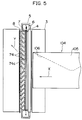
- FIG 5 is a view explaining a state when an envelope is conveyed on the same guiding member 7 as Figure 2.
- the receiving substrate such as an envelope 104 has generally a flap portion 105 for sealing up by sticking it down.
- the flap portion 105 has not been stuck down yet when the image is formed, and it faces down during conveying, thus the flap portion 105 hangs down. Therefore, an edge 106 of the flap portion 105 may enter into one of the spaces between the ribs 74 and may come into contact with one of upright walls 74c of the ribs 74. It is noted that the upright walls 74c extend in an intersecting direction to the feed direction, and said one of the upright walls 74c guides the edge 106 of the envelope 104.
- Figure 6 is a plane view showing this embodiment
- Figure 7 is a sectional view taken on line VII-VII in Figure 6
- Figure 8 is an enlarged perspective view showing a part of ribs 74 of a guiding member 27 of Figure 6.
- the ribs 74 spread out like an unfolded fan.
- the ribs 74 comprises guide portions 74a provided at the upper portion thereof for guiding an envelope 104 and assisting guide portions are provided in the spaces therebetween. More minutely, each of the assisting guide portions is provided at an upstream or outside portion of each of the ribs 74 and assisting guide portions are declining portions 74b which decline from the guide portions 74a towards lowermost portions 72a of the spaces. The lowermost portions 72a of the spaces are coincident with an upper surface of said flat portion 72.
- the guiding member 27 has such a constructure, even if the flap portion 105 of the envelope 104 enters into one of the spaces between the ribs 4 during conveying, the edge 106 of the flap portion 105 is guided to the guide portions 74a by the declining portions 74b. Accordingly, the envelope 104 does not turn aside and does not jam. Moreover, the guiding member 27 still has spaces between the ribs 74 where said charge removing action of the charge removing brush 8 can spread over, as shown in dot lines in Figure 7. Accordingly, the charge removing action is not disturbed or limited by the guiding member 27.
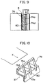
- FIGS 9 and 10 show another embodiment of the assisting guide portions which constitute a part of a guiding member 37.
- This embodiment has flat tables 74d used as assisting guide portions instead of the declining portions 74b.
- Each of the flat tables 74d is also provided at an upstream or outside portion of each of the ribs 74 which extends in the intersecting direction to the feed direction.
- the flat tables 74d are a little lower than the guide portions 74a but higher than the lowermost portions 72a of the spaces.
- the flat tables 74d and the lowermost portions 72a of the spaces are disposed mutually.
- Space portions 80 are formed where the lowermost portions 72a are positioned. That is, each of the spaces between ribs 74 is divided into two parts.
- One of the parts which faces the charge removing brush 8 is remained as each of said space portions 80.
- the other of the parts which is positioned in the vicinity of the transfer discharger 5 is filled in as each of said flat tables 74d.
- Each side of the flat tables 74d which faces each of the space portions 80 is preferably parallel to the feed direction. Accordingly, even if an envelope 104 enters into the flat tables 74d, the envelope 104 is guided to the guide portions 74a easily. Since the guide portions 74a are a little higher than the flat tables 74d and spread out like an unfolded fan, the envelope 104 does not wave in an intersecting direction to the feed direction. Moreover, the charge removing action of the charge removing brush 8 spreads over said space portions 80 and, therefore, the charges on the rear surface of the envelope 104 can be removed effectively.
- the assisting guide portions are not necessary to provide in whole of the guiding member as disclosed in the above embodiments shown in Figures 6 and 9, but they may be provided only in the parts where the flap portions of the regular sizes' envelopes apt to hang down.
- the guiding member in Figures 6 to 10 may be made of insulating material and antistatic material. The antistatic material is provided on said insulating material and is provided in at least a part of the guiding member which comes into contact with the envelope 104.
- the guiding member comprising the asisting guide portions is disposed in the vicinity of the transfer discharger 5.
- the guiding member is not limited to the above embodiments but otherwise various changes and modifications may be adopted.
- the ribs may be disposed so that a downstream side of each rib tends inward, contrary to the embodiment of Figure 2.
- the guiding member 17 comprises the upper guiding portion 76 made of an antistatic material and the lower guiding portion 75 made of an insulating material.
- the guiding member 17 may otherwise be made of an antistatic material in only a part thereof which comes into contact with the sheet material. Further, the guiding member 17 may otherwise be made of an antistatic material in whole.
- the charge removing brush 8 is used as charge removing means.
- it may otherwise be a metallic roller having a rough surface removing charges by projecting portions.
- it may otherwise be a saw-shaped charge removing member, or it may be a needle-shaped charge removing member.
Landscapes
- Physics & Mathematics (AREA)
- General Physics & Mathematics (AREA)
- Electrostatic Charge, Transfer And Separation In Electrography (AREA)
- Feeding Of Articles By Means Other Than Belts Or Rollers (AREA)
Claims (13)
- Un appareil de formation d'images du type transfert comprenant :dans lequel ledit organe isolant (7) a une forme de crochet en section transversale, comprenantun organe de support d'images (1) ayant un faible rayon de courbure,des moyens de transfert (5, 6) pour transférer par voie électrostatique une image en toner formée sur ledit organe de support d'images (1) sur un substrat (S) récepteur, ledit substrat (S) étant séparé de l'organe de support d'images (1) du fait de sa rigidité et/ou de son poids propre, lesdits moyens de transfert (5, 6) comprenant un conducteur de décharge (6) disposé à l'intérieur d'un boítier (5A) en matériau électro-conducteur ayant une section transversale en forme de U dans laquelle la forme de U s'ouvre vers l'organe de support d'images (1),un organe isolant (7) disposé du côté aval du boítier (5A) dans la direction d'amenée du substrat, ledit organe isolant (7) étant muni d'une pluralité de nervures (74) dessus pour guider le substrat (S), les nervures (74) étant disposées dans une direction croisant la direction d'amenée, avec des espaces entre elles etdes moyens d'enlèvement de charges (8) pour attirer des charges depuis la surface arrière du substrat (S) après séparation d'avec l'organe de support d'images (1), lesdits moyens d'enlèvement de charges (8) étant faits d'un matériau électro-conducteur et étant disposés au voisinage immédiat du côté aval dudit organe isolant (7), grâce à quoi l'action d'enlèvement de charges desdits moyens d'enlèvement de charges (8) s'étend sur lesdits espaces entre les nervures (74) et grâce à quoi des charges sur la surface arrière du substrat (S) sont enlevées pendant que le substrat (S) est guidé par les nervures (74),une première section verticale (71) en contact avec la surface du côté aval dudit boítier (5A) en forme de U,une section plane (72) agencée pour couvrir une portion aval de l'ouverture du boítier (5A) en forme de U, etune seconde section verticale (73) positionnée à l'extrémité amont de la section plane (72) et faisant saillie vers l'organe de support d'images (1),ladite section plane (72) et ladite seconde section verticale (73) régulant la largeur de la surface de décharge etlesdites nervures (74) pour guider le substrat (S) sont disposées sur la surface supérieure de la section plane (72) adjacentes à ladite seconde section verticale (73).
- Un appareil de formation d'images selon la revendication 1,
dans lequel lesdites nervures (74) s'étalent comme un éventail déployé. - Un appareil de formation d'images selon la revendication 1 ou 2,
dans lequel ledit organe isolant (7) comprend une pluralité de portions de guidage (74b, 74d) auxiliaires disposées dans au moins certains desdits espaces pour guider le substrat (S) vers des portions de guidage (74a) supérieures des nervures. - Un appareil de formation d'images selon la revendication 1, 2 ou 3,
dans lequel un matériau antistatique est disposé sur ledit organe isolant (7) au moins à une portion supérieure (74a) qui est en contact avec le substrat. - Un appareil de formation d'images selon l'une quelconque des revendications 1 à 4,
dans lequel lesdits moyens d'enlèvement de charges (8) sont des moyens d'enlèvement de charges du type brosse. - Un appareil de formation d'images selon l'une quelconque des revendications 1 à 5,
dans lequel une extrémité desdits moyens d'enlèvement de charges (8) est disposée à une position plus bas que des portions supérieures (74a) des nervures (74), grâce à quoi le substrat récepteur est hors de contact avec les moyens d'enlèvement de charges (8). - Un appareil de formation d'images selon l'une quelconque des revendications 1 à 6,
dans lequel ledit organe de support d'images (1) n'a pas plus de 50 mm de diamètre. - Un appareil de formation d'images selon la revendication 3,
dans lequel lesdites nervures (74) sont inclinées vers des portions (72) les plus basses des espaces et les portions inclinées (74b) constituent lesdites portions de guidage auxiliaires. - Un appareil de formation d'images selon la revendication 3,
dans lequel lesdites portions de guidage auxiliaires sont des tables planes (74d) qui sont plus bas que lesdites portions de guidage supérieures (74a) mais plus haut que les portions (72a) les plus basses des espaces (80), lesdites tables planes (74d) et lesdites portions (72a) les plus basses des espaces (80) étant disposées proches les unes des autres entre les nervures. - Un appareil de formation d'images selon la revendication 4,
dans lequel ledit organe isolant (7) comprend une portion de guidage inférieure (75) faite d'un matériau isolant et une portion de guidage supérieure (76) faite d'un matériau antistatique qui est disposé sur ladite portion de guidage inférieure (75). - Un appareil de formation d'images selon la revendication 10,
dans lequel ladite portion de guidage supérieure (76) est faite d'une résine. - Un appareil de formation d'images selon la revendication 10 ou 11,
dans lequel ledit organe isolant (7) est complètement fait d'un matériau antistatique. - Un appareil de formation d'images selon la revendication 10, 11 ou 12,
dans lequel ledit matériau antistatique a une résistivité superficielle de 1 x 10⁸ ohm-cm à 1 x 10¹² ohm-cm, de préférence de 1 x 10¹¹ ohm-cm à 1 x 10¹² ohm-cm.
Applications Claiming Priority (6)
| Application Number | Priority Date | Filing Date | Title |
|---|---|---|---|
| JP1989060253U JPH0750763Y2 (ja) | 1989-05-24 | 1989-05-24 | 転写装置 |
| JP60253/89U | 1989-05-24 | ||
| JP1989077908U JPH0716664Y2 (ja) | 1989-06-30 | 1989-06-30 | 放電器における転写材搬送ガイド |
| JP77908/89U | 1989-06-30 | ||
| JP1222673A JPH0384579A (ja) | 1989-08-28 | 1989-08-28 | 転写装置 |
| JP222673/89 | 1989-08-28 |
Publications (3)
| Publication Number | Publication Date |
|---|---|
| EP0399500A2 EP0399500A2 (fr) | 1990-11-28 |
| EP0399500A3 EP0399500A3 (fr) | 1991-09-04 |
| EP0399500B1 true EP0399500B1 (fr) | 1998-09-02 |
Family
ID=27297127
Family Applications (1)
| Application Number | Title | Priority Date | Filing Date |
|---|---|---|---|
| EP90109811A Expired - Lifetime EP0399500B1 (fr) | 1989-05-24 | 1990-05-23 | Appareil de formation d'images |
Country Status (4)
| Country | Link |
|---|---|
| US (1) | US5130752A (fr) |
| EP (1) | EP0399500B1 (fr) |
| KR (1) | KR930007498B1 (fr) |
| DE (1) | DE69032610T2 (fr) |
Families Citing this family (26)
| Publication number | Priority date | Publication date | Assignee | Title |
|---|---|---|---|---|
| WO1992018912A1 (fr) * | 1991-04-12 | 1992-10-29 | Hitachi, Ltd. | Dispositif d'enregistrement electrophotographique |
| EP0530491B1 (fr) * | 1991-08-02 | 1997-05-07 | Minolta Co., Ltd. | Appareil électrophotographique de formation d'images muni d'une unité de formation d'images amovible |
| JPH05107935A (ja) * | 1991-10-18 | 1993-04-30 | Mita Ind Co Ltd | 転写分離装置 |
| DE4305686C2 (de) * | 1992-02-24 | 1999-07-15 | Fujitsu Ltd | Tonerbild-Übertragungsvorrichtung einschließlich einer Übertragungsladevorrichtung und einer Wechselspannungs-Ladungslöschvorrichtung |
| JP2798868B2 (ja) * | 1992-11-26 | 1998-09-17 | 三田工業株式会社 | 転写装置 |
| US5633703A (en) * | 1993-09-16 | 1997-05-27 | Konica Corporation | Image forming apparatus having transfer roller and separation brush |
| JP3223004B2 (ja) * | 1993-09-21 | 2001-10-29 | 株式会社東芝 | 画像形成装置 |
| US5450187A (en) * | 1993-12-27 | 1995-09-12 | Xerox Corporation | Envelope processing in a laser printer for higher reliability, usability and throughput |
| US5713063A (en) * | 1994-08-03 | 1998-01-27 | Kabushiki Kaisha Toshiba | Electrostatic image transfer device having a two level transfer voltage for improving image quality at leading and trailing edge regions |
| US5515147A (en) * | 1994-10-28 | 1996-05-07 | Eastman Kodak Company | Mechanism for substantially preventing trail edge smear of an image on a receiver member |
| US5519477A (en) * | 1994-11-21 | 1996-05-21 | Xerox Corporation | Post transfer corrugator |
| JP3671617B2 (ja) * | 1997-09-01 | 2005-07-13 | コニカミノルタホールディングス株式会社 | 画像形成装置 |
| US5870661A (en) * | 1998-05-04 | 1999-02-09 | Tektronix, Inc. | Apparatus and method for controlling media temperature in an imaging apparatus |
| US6169875B1 (en) | 1998-05-29 | 2001-01-02 | Xerox Corporation | Envelope transport structure |
| US6125256A (en) * | 1998-10-07 | 2000-09-26 | Xerox Corporation | Apparatus and method for reducing media wrinkling in an imaging apparatus |
| JP3748385B2 (ja) * | 2001-03-16 | 2006-02-22 | シャープ株式会社 | 画像形成装置 |
| DE10121289A1 (de) | 2001-05-02 | 2002-11-07 | Nexpress Solutions Llc | Vorrichtung zum Führen von Druckträgern durch eine Entladevorrichtung |
| JP2003215934A (ja) * | 2002-01-24 | 2003-07-30 | Fuji Xerox Co Ltd | プリンタおよび転写ユニット |
| US6687479B2 (en) | 2002-05-31 | 2004-02-03 | Xerox Corporation | Paper input guide for a transfer zone in a xerographic printing apparatus |
| JP2004170905A (ja) * | 2002-10-29 | 2004-06-17 | Sharp Corp | 用紙剥離機構およびプロセスカートリッジ |
| JP4112518B2 (ja) * | 2004-03-22 | 2008-07-02 | シャープ株式会社 | 画像形成装置 |
| KR100561368B1 (ko) * | 2004-10-18 | 2006-03-17 | 삼성전자주식회사 | 인쇄매체 배출안내유닛 및 이를 구비한 습식 화상형성장치 |
| JP2007333938A (ja) * | 2006-06-14 | 2007-12-27 | Fuji Xerox Co Ltd | 像担持体及び画像形成装置 |
| JP5444621B2 (ja) * | 2008-02-26 | 2014-03-19 | 株式会社リコー | 孔版印刷装置 |
| JP5779864B2 (ja) * | 2010-11-09 | 2015-09-16 | 富士ゼロックス株式会社 | 画像形成装置および除電装置 |
| JP6468845B2 (ja) * | 2015-01-07 | 2019-02-13 | キヤノン株式会社 | 画像形成装置 |
Family Cites Families (19)
| Publication number | Priority date | Publication date | Assignee | Title |
|---|---|---|---|---|
| NL294912A (fr) * | 1962-07-06 | |||
| US3877560A (en) * | 1970-02-27 | 1975-04-15 | Suwa Seikosha Kk | Paper guide for a compact flying printer |
| US4214740A (en) * | 1978-05-02 | 1980-07-29 | Xerox Corporation | Sheet reversing mechanism |
| US4369729A (en) * | 1980-08-18 | 1983-01-25 | Canon Kabushiki Kaisha | Image recording apparatus |
| DE3136310A1 (de) * | 1981-09-12 | 1983-03-24 | Develop Dr. Eisbein Gmbh & Co, 7016 Gerlingen | Vorrichtung zum zufuehren von blaettern zu einer fixiereinrichtung eines kopiergeraetes |
| JPS5993474A (ja) * | 1982-11-18 | 1984-05-29 | Sharp Corp | 電子写真複写装置 |
| US4579441A (en) * | 1982-12-03 | 1986-04-01 | Xerox Corporation | Detacking apparatus |
| JPS59126571A (ja) * | 1983-01-10 | 1984-07-21 | Canon Inc | 画像形成装置 |
| JPS6026560A (ja) * | 1983-07-22 | 1985-02-09 | Canon Inc | シ−ト送り装置 |
| JPS61162073A (ja) * | 1985-01-10 | 1986-07-22 | Canon Inc | 画像形成装置 |
| US4739363A (en) * | 1985-03-26 | 1988-04-19 | Canon Kabushiki Kaisha | Image forming apparatus |
| US4769676A (en) * | 1986-03-04 | 1988-09-06 | Kabushiki Kaisha Toshiba | Image forming apparatus including means for removing residual toner |
| US4801975A (en) * | 1986-04-18 | 1989-01-31 | Mita Industrial Co. Ltd. | Eraser lamp and transparent guide plate in electrostatic image transfer |
| US4829334A (en) * | 1986-05-28 | 1989-05-09 | Mita Industrial Co., Ltd. | Image-forming machine having a cover member for covering part of an image bearing member |
| US4744555A (en) * | 1986-12-22 | 1988-05-17 | Xerox Corporation | Sheet transport and registration apparatus |
| JPS63163385A (ja) * | 1986-12-25 | 1988-07-06 | Mita Ind Co Ltd | 複写紙搬送装置 |
| DE3709659C2 (de) * | 1987-03-24 | 1995-06-08 | Licentia Gmbh | Vorrichtung zum Ausrichten von Briefen und ähnlichem flachen Fördergut |
| US4843214A (en) * | 1987-05-07 | 1989-06-27 | Ricoh Company, Ltd. | Heat roll type arrangement for electrostatic recording apparatus |
| JP2560723B2 (ja) * | 1987-05-25 | 1996-12-04 | 日本電気株式会社 | 用紙走行ガイドプレ−ト |
-
1990
- 1990-05-15 US US07/523,537 patent/US5130752A/en not_active Expired - Fee Related
- 1990-05-23 DE DE69032610T patent/DE69032610T2/de not_active Expired - Fee Related
- 1990-05-23 EP EP90109811A patent/EP0399500B1/fr not_active Expired - Lifetime
- 1990-05-24 KR KR1019900007720A patent/KR930007498B1/ko not_active Expired - Fee Related
Non-Patent Citations (1)
| Title |
|---|
| PATENT ABSTRACTS OF JAPAN vol. 8, no. 137 (P-282)(1574), 26 June 1984; & JP - A - 5938770 (FUJI XEROX) 02.03.1984 * |
Also Published As
| Publication number | Publication date |
|---|---|
| KR930007498B1 (ko) | 1993-08-11 |
| EP0399500A2 (fr) | 1990-11-28 |
| EP0399500A3 (fr) | 1991-09-04 |
| DE69032610T2 (de) | 1999-04-22 |
| KR900018769A (ko) | 1990-12-22 |
| US5130752A (en) | 1992-07-14 |
| DE69032610D1 (de) | 1998-10-08 |
Similar Documents
| Publication | Publication Date | Title |
|---|---|---|
| EP0399500B1 (fr) | Appareil de formation d'images | |
| JPH0741204A (ja) | 画像形成装置 | |
| JPH0760282B2 (ja) | 画像形成装置 | |
| JP3330721B2 (ja) | 転写ベルト装置 | |
| US6678494B2 (en) | Image forming apparatus with transfer material guide | |
| US5826153A (en) | Image-forming machine | |
| JP2515306Y2 (ja) | 紙葉排出装置 | |
| JP2023183612A (ja) | 画像形成装置 | |
| JP3902683B2 (ja) | 画像形成装置の作像ユニット | |
| JP2685658B2 (ja) | 転写分離装置 | |
| JP3210198B2 (ja) | コロナ放電装置 | |
| US7123871B2 (en) | Neutralizing apparatus and image forming apparatus having the neutralizing apparatus | |
| JP3217159B2 (ja) | 転写紙の分離装置 | |
| JP2823343B2 (ja) | 電子写真装置 | |
| JPH0713439A (ja) | 画像形成装置における転写材剥離装置 | |
| JPH07306599A (ja) | 画像形成装置 | |
| JPH0750763Y2 (ja) | 転写装置 | |
| JP2547444Y2 (ja) | 画像形成装置 | |
| JPH06222682A (ja) | 転写分離装置 | |
| JPH07110625A (ja) | 画像形成装置 | |
| JP2751203B2 (ja) | 帯電装置 | |
| JP2003215934A (ja) | プリンタおよび転写ユニット | |
| JPH03100665A (ja) | 画像形成装置に着脱可能なプロセスカートリッジ | |
| JPH01186988A (ja) | 静電分離装置 | |
| JP2001249550A (ja) | 画像形成装置 |
Legal Events
| Date | Code | Title | Description |
|---|---|---|---|
| PUAI | Public reference made under article 153(3) epc to a published international application that has entered the european phase |
Free format text: ORIGINAL CODE: 0009012 |
|
| AK | Designated contracting states |
Kind code of ref document: A2 Designated state(s): DE FR GB NL |
|
| 17P | Request for examination filed |
Effective date: 19901212 |
|
| PUAL | Search report despatched |
Free format text: ORIGINAL CODE: 0009013 |
|
| AK | Designated contracting states |
Kind code of ref document: A3 Designated state(s): DE FR GB NL |
|
| 17Q | First examination report despatched |
Effective date: 19921030 |
|
| APAB | Appeal dossier modified |
Free format text: ORIGINAL CODE: EPIDOS NOAPE |
|
| GRAG | Despatch of communication of intention to grant |
Free format text: ORIGINAL CODE: EPIDOS AGRA |
|
| GRAG | Despatch of communication of intention to grant |
Free format text: ORIGINAL CODE: EPIDOS AGRA |
|
| GRAH | Despatch of communication of intention to grant a patent |
Free format text: ORIGINAL CODE: EPIDOS IGRA |
|
| GRAH | Despatch of communication of intention to grant a patent |
Free format text: ORIGINAL CODE: EPIDOS IGRA |
|
| GRAA | (expected) grant |
Free format text: ORIGINAL CODE: 0009210 |
|
| AK | Designated contracting states |
Kind code of ref document: B1 Designated state(s): DE FR GB NL |
|
| PG25 | Lapsed in a contracting state [announced via postgrant information from national office to epo] |
Ref country code: NL Free format text: LAPSE BECAUSE OF FAILURE TO SUBMIT A TRANSLATION OF THE DESCRIPTION OR TO PAY THE FEE WITHIN THE PRESCRIBED TIME-LIMIT Effective date: 19980902 |
|
| REF | Corresponds to: |
Ref document number: 69032610 Country of ref document: DE Date of ref document: 19981008 |
|
| ET | Fr: translation filed | ||
| NLV1 | Nl: lapsed or annulled due to failure to fulfill the requirements of art. 29p and 29m of the patents act | ||
| PGFP | Annual fee paid to national office [announced via postgrant information from national office to epo] |
Ref country code: GB Payment date: 19990504 Year of fee payment: 10 |
|
| PLBE | No opposition filed within time limit |
Free format text: ORIGINAL CODE: 0009261 |
|
| STAA | Information on the status of an ep patent application or granted ep patent |
Free format text: STATUS: NO OPPOSITION FILED WITHIN TIME LIMIT |
|
| PGFP | Annual fee paid to national office [announced via postgrant information from national office to epo] |
Ref country code: DE Payment date: 19990727 Year of fee payment: 10 |
|
| 26N | No opposition filed | ||
| PG25 | Lapsed in a contracting state [announced via postgrant information from national office to epo] |
Ref country code: FR Free format text: LAPSE BECAUSE OF NON-PAYMENT OF DUE FEES Effective date: 20000131 |
|
| REG | Reference to a national code |
Ref country code: FR Ref legal event code: ST |
|
| PG25 | Lapsed in a contracting state [announced via postgrant information from national office to epo] |
Ref country code: GB Free format text: LAPSE BECAUSE OF NON-PAYMENT OF DUE FEES Effective date: 20000523 |
|
| GBPC | Gb: european patent ceased through non-payment of renewal fee |
Effective date: 20000523 |
|
| PG25 | Lapsed in a contracting state [announced via postgrant information from national office to epo] |
Ref country code: DE Free format text: LAPSE BECAUSE OF NON-PAYMENT OF DUE FEES Effective date: 20010301 |
|
| APAH | Appeal reference modified |
Free format text: ORIGINAL CODE: EPIDOSCREFNO |