EP0399546A1 - Dispositif d'affichage d'images et affiches transparentes - Google Patents
Dispositif d'affichage d'images et affiches transparentes Download PDFInfo
- Publication number
- EP0399546A1 EP0399546A1 EP90109948A EP90109948A EP0399546A1 EP 0399546 A1 EP0399546 A1 EP 0399546A1 EP 90109948 A EP90109948 A EP 90109948A EP 90109948 A EP90109948 A EP 90109948A EP 0399546 A1 EP0399546 A1 EP 0399546A1
- Authority
- EP
- European Patent Office
- Prior art keywords
- housing
- conveyor belt
- images
- rollers
- drive
- Prior art date
- Legal status (The legal status is an assumption and is not a legal conclusion. Google has not performed a legal analysis and makes no representation as to the accuracy of the status listed.)
- Withdrawn
Links
- 239000011324 bead Substances 0.000 description 3
- 238000006073 displacement reaction Methods 0.000 description 2
- 230000035882 stress Effects 0.000 description 2
- 230000001360 synchronised effect Effects 0.000 description 2
- 239000002390 adhesive tape Substances 0.000 description 1
- 238000007786 electrostatic charging Methods 0.000 description 1
- 230000001771 impaired effect Effects 0.000 description 1
- 230000007774 longterm Effects 0.000 description 1
- 239000000463 material Substances 0.000 description 1
- 239000004033 plastic Substances 0.000 description 1
- 239000002985 plastic film Substances 0.000 description 1
- 229920006255 plastic film Polymers 0.000 description 1
- 230000008646 thermal stress Effects 0.000 description 1
Images

Classifications
-
- G—PHYSICS
- G09—EDUCATION; CRYPTOGRAPHY; DISPLAY; ADVERTISING; SEALS
- G09F—DISPLAYING; ADVERTISING; SIGNS; LABELS OR NAME-PLATES; SEALS
- G09F11/00—Indicating arrangements for variable information in which the complete information is permanently attached to a movable support which brings it to the display position
- G09F11/12—Indicating arrangements for variable information in which the complete information is permanently attached to a movable support which brings it to the display position the display elements being carried by endless belts, chains, or the like
- G09F11/15—Indicating arrangements for variable information in which the complete information is permanently attached to a movable support which brings it to the display position the display elements being carried by endless belts, chains, or the like the elements being flexible sheets
Definitions
- the invention relates to a device for the display of translucent images and posters, which are arranged interchangeably on a translucent, endless conveyor belt, which is guided over driven transport rollers which are located in a box-shaped housing, the front of which has a window, behind which a light source is located with which are to be examined sequentially.
- Devices are therefore more advantageous in which a plurality of images are presented to the viewer for viewing by transport occurring at short time intervals. These devices differ generically in that they either have several windows in which different images can be viewed simultaneously or only have one window in which a large number of images can be viewed in chronological succession.
- the object of the invention is a device for to display a sequence of images while simultaneously displaying images in several windows, which is suitable on the one hand for the reproduction of a large number of images and on the other hand requires only a small technical outlay, so that they can be widely disseminated due to low production costs for a wide variety of different Possible applications.
- windows are arranged, on the sides of which drive rollers are for an endless conveyor belt which carries a plurality of images and is additionally guided over at least two deflection rollers, which are inside of the housing.
- deflection rollers in the interior of the housing allow the conveyor belt to be used and thus also the number of pictures intended for a display to be significantly increased, so that not only the possible information content is significantly increased compared to known devices, but also the duration of the information and thus the connection of the viewer to the product for which the advertising or information is being operated.
- a pair of drive rollers is arranged in the corner of the housing and the conveyor belt is guided inwards from one of these rollers into the housing and there around a deflection roller and back, around the other drive roller, which is in the same corner, because this makes the possible usable Length of the conveyor belt significantly increased.
- this design is not limited to the use of a pair of drive rollers in one corner of the housing. Rather, it can be used for each corner by arranging a pair of drive rollers and a deflection roller assigned to them.
- the housing is preferably of square cross section. Furthermore, it helps to simplify the design effort if all drive rollers are connected to one another via a common drive belt, such as a toothed belt, so that their synchronous operation is ensured.
- the interchangeable images can be hung up on the conveyor belt in a known manner, either with their upper edge or with the edge at the front in the direction of transport, the rear edge also advantageously requiring a holder.
- the conveyor belt rests directly on a roller and carries the image on its outside which travels a long way during its transport, so that it must be displaceable relative to the conveyor belt, while after a change of direction the image is on the inside and the external conveyor belt travels a long way, so that there are continual displacements to one another, which result in the brackets being subjected to mechanical stress of more than a thousand times a day, to which thermal stress due to the heat of the light sources is continuously added.
- the conveyor belt film which generally consists of a translucent plastic material, is electrostatically charged, so that the free movement of the images relative to the conveyor belt is impaired and the stress on the image holders is thereby increased.
- the drive rollers are provided with track grooves for the push buttons.
- the images can additionally be guided in elongated holes with their image edge at the back in the direction of flow, so that they can move during transport in the horizontal direction to the conveyor belt during their deflection, while at the same time guiding in terms of height is ensured.
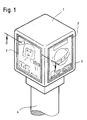
- the device for the display of a large number of images has a square cross-section housing 1 with four side walls, in each of which a window is installed for the respective representation of an image, so that four different images can be viewed from four sides at the same time alternate continuously with other images at short intervals.
- the housing 1 rests on a column 4 which can be driven by a motor not shown in the drawing, so that the housing can also be set in rotation if necessary.
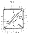
- 3 drive rollers 5 are arranged behind the four corner pillars, which carry a gear 6, which is in engagement with a toothed belt 7, which drives all drive rollers 5 and 5 'for synchronous rotation.
- one drive roller 5 in the drawing in FIG. 2 is provided at the bottom right with an additional pinion 8 which is driven by a drive belt 10 via a stepper motor 9.
- This mechanism serves to drive a conveyor belt 12, which consists of a translucent plastic film and carries the interchangeably attached images 28, which are to be put on display in the windows 2.
- the conveyor belt runs according to the arrows 15 and the deflection rollers 13 and 14 turn counterclockwise according to the arrow 16.
- light sources such as fluorescent tubes 18 are provided, one of which is located behind each window 2.
- the drive rollers 5 and 5 ' are provided according to Figure 3 with rubber rollers 20 and 21, between which track grooves 22 are kept free, in which the push buttons 23 rotate with which the images 28 are attached to the conveyor belt 12, so that the conveyor belt 12 firmly on the driven rollers 20 and 21 can rest for a perfect frictional connection.
- the push buttons 23 consist of an upper part 24 with a hole, the edge of which is resilient, and a lower part 25, which carries a pin 26 onto which the upper part 24 is to be attached.
- the lower parts of the snap fasteners can be attached to the conveyor belt 12 so that their pins extend through holes in the image which is then interchangeably attached to the upper portion of the snap fasteners.
- the image edge sections lying in the conveying direction 15 are each to be pushed under a flap or tab 27, so that a pin 26 extends through a hole in the image 28 and the image is to be secured by pressing on the upper part 24, which is connected to the tab or the Flap 27 is connected.
- a cross-country guide is provided at the rear edge of the image, which consists of an elongated hole 31 which is incorporated in a tab 30 connected to the image 28 and the receptacle of the pin 26 from Lower part 25 of a push button 23 is used.
- a correct displacement of the image 28 to the conveyor belt 12 is further promoted by the fact that the conveyor belt 12 is provided with knobs or beads that protrude on the image side, which are arranged in rows in a punctiform manner, so that the image 28 for the purpose of avoiding electrostatic Charging of the transport film 32 is lying loosely on it, as shown in FIG 6 on a larger scale. It ver it is clear, however, that continuous protruding webs in the manner of beads can also be provided instead of these individual punctiform knobs.
- FIG. 6 also shows the design of a push button 23, the width "A" of which is less than the width of the track groove 22, so that the push buttons do not come to rest on the roller rollers 20 or 21.
Landscapes
- Physics & Mathematics (AREA)
- General Physics & Mathematics (AREA)
- Engineering & Computer Science (AREA)
- Theoretical Computer Science (AREA)
- Displays For Variable Information Using Movable Means (AREA)
Applications Claiming Priority (2)
| Application Number | Priority Date | Filing Date | Title |
|---|---|---|---|
| DE3917133 | 1989-05-26 | ||
| DE19893917133 DE3917133A1 (de) | 1989-05-26 | 1989-05-26 | Vorrichtung zur schaustellung von lichtdurchlaessigen bildern und plakaten |
Publications (1)
| Publication Number | Publication Date |
|---|---|
| EP0399546A1 true EP0399546A1 (fr) | 1990-11-28 |
Family
ID=6381433
Family Applications (1)
| Application Number | Title | Priority Date | Filing Date |
|---|---|---|---|
| EP90109948A Withdrawn EP0399546A1 (fr) | 1989-05-26 | 1990-05-25 | Dispositif d'affichage d'images et affiches transparentes |
Country Status (4)
| Country | Link |
|---|---|
| EP (1) | EP0399546A1 (fr) |
| JP (1) | JPH04500280A (fr) |
| DE (1) | DE3917133A1 (fr) |
| WO (1) | WO1990014654A1 (fr) |
Cited By (7)
| Publication number | Priority date | Publication date | Assignee | Title |
|---|---|---|---|---|
| EP0617393A1 (fr) * | 1993-03-26 | 1994-09-28 | Avenir Havas Media | Dispositif d'affichage à déroulement horizontal, et chargement d'affiche afférent |
| FR2758203A1 (fr) * | 1997-01-08 | 1998-07-10 | Avenir France | Dispositif antistatique pour panneau d'affichage |
| WO2004032105A3 (fr) * | 2002-09-27 | 2004-06-17 | Braehmig Fluidautomation Gmbh | Dispositif publicitaire de surface importante destine a des panneaux et procede de commande du changement des panneaux |
| WO2004079693A3 (fr) * | 2003-02-27 | 2004-10-14 | Jean Michel Baroche | Dispositif d'affichage a bande sans fin defilante |
| WO2005052896A1 (fr) * | 2003-11-26 | 2005-06-09 | Emil Pramatarov | Dispositif de publicite |
| WO2005109382A3 (fr) * | 2004-05-06 | 2006-03-09 | Dietmar Goetz | Tour publicitaire |
| RU2469413C2 (ru) * | 2011-02-11 | 2012-12-10 | Игорь Сергеевич Ковалёв | Рекламное устройство ковалёва и.с. |
Families Citing this family (2)
| Publication number | Priority date | Publication date | Assignee | Title |
|---|---|---|---|---|
| DE9113178U1 (de) * | 1991-10-23 | 1991-12-19 | Marketing-Displays Produktionsgesellschaft für Werbe- und Verkaufsförderungssysteme mbH, 5000 Köln | Plakatpräsentationsvorrichtung |
| DE20211279U1 (de) | 2002-07-19 | 2002-12-12 | Mega Media Communications GmbH, 81241 München | Gehäuse zur Präsentation flexibler Informationsträger |
Citations (4)
| Publication number | Priority date | Publication date | Assignee | Title |
|---|---|---|---|---|
| FR699488A (fr) * | 1929-07-01 | 1931-02-16 | Dispositif pour la présentation d'images publicitaires destinées à la réclame diurne et nocturne, et procédés pour leur production | |
| US2867050A (en) * | 1953-11-05 | 1959-01-06 | Marie S Westfall | Moving message projector |
| US4005535A (en) * | 1974-04-11 | 1977-02-01 | Davis James F | Progressively revealed display |
| DE8906474U1 (de) * | 1989-05-26 | 1989-07-20 | Marjanovic, Marco, 2000 Hamburg | Vorrichtung zur Schaustellung von lichtdurchlässigen Bildern und Plakaten |
-
1989
- 1989-05-26 DE DE19893917133 patent/DE3917133A1/de not_active Withdrawn
-
1990
- 1990-05-25 EP EP90109948A patent/EP0399546A1/fr not_active Withdrawn
- 1990-05-25 JP JP2507945A patent/JPH04500280A/ja active Pending
- 1990-05-25 WO PCT/EP1990/000848 patent/WO1990014654A1/fr not_active Ceased
Patent Citations (4)
| Publication number | Priority date | Publication date | Assignee | Title |
|---|---|---|---|---|
| FR699488A (fr) * | 1929-07-01 | 1931-02-16 | Dispositif pour la présentation d'images publicitaires destinées à la réclame diurne et nocturne, et procédés pour leur production | |
| US2867050A (en) * | 1953-11-05 | 1959-01-06 | Marie S Westfall | Moving message projector |
| US4005535A (en) * | 1974-04-11 | 1977-02-01 | Davis James F | Progressively revealed display |
| DE8906474U1 (de) * | 1989-05-26 | 1989-07-20 | Marjanovic, Marco, 2000 Hamburg | Vorrichtung zur Schaustellung von lichtdurchlässigen Bildern und Plakaten |
Cited By (9)
| Publication number | Priority date | Publication date | Assignee | Title |
|---|---|---|---|---|
| EP0617393A1 (fr) * | 1993-03-26 | 1994-09-28 | Avenir Havas Media | Dispositif d'affichage à déroulement horizontal, et chargement d'affiche afférent |
| FR2703176A1 (fr) * | 1993-03-26 | 1994-09-30 | Havas Media Avenir | Dispositif d'affichage à déroulement horizontal. |
| FR2758203A1 (fr) * | 1997-01-08 | 1998-07-10 | Avenir France | Dispositif antistatique pour panneau d'affichage |
| WO2004032105A3 (fr) * | 2002-09-27 | 2004-06-17 | Braehmig Fluidautomation Gmbh | Dispositif publicitaire de surface importante destine a des panneaux et procede de commande du changement des panneaux |
| WO2004079693A3 (fr) * | 2003-02-27 | 2004-10-14 | Jean Michel Baroche | Dispositif d'affichage a bande sans fin defilante |
| WO2005052896A1 (fr) * | 2003-11-26 | 2005-06-09 | Emil Pramatarov | Dispositif de publicite |
| EA008348B1 (ru) * | 2003-11-26 | 2007-04-27 | Эмил Праматаров | Устройство для размещения рекламы |
| WO2005109382A3 (fr) * | 2004-05-06 | 2006-03-09 | Dietmar Goetz | Tour publicitaire |
| RU2469413C2 (ru) * | 2011-02-11 | 2012-12-10 | Игорь Сергеевич Ковалёв | Рекламное устройство ковалёва и.с. |
Also Published As
| Publication number | Publication date |
|---|---|
| DE3917133A1 (de) | 1990-11-29 |
| WO1990014654A1 (fr) | 1990-11-29 |
| JPH04500280A (ja) | 1992-01-16 |
Similar Documents
| Publication | Publication Date | Title |
|---|---|---|
| EP0247349A2 (fr) | Etiquette de prix | |
| DE69307623T2 (de) | Werbeschild aus mehreren Tafeln, mit dem mehrere Botschaften zusammengestellt werden können, die einzeln ausgewählt und angezeigt werden | |
| WO1990014654A1 (fr) | Dispositif de visualisation d'images et d'affiches par transparence | |
| DE2030140C3 (de) | Vorführungsvorrichtung | |
| DE2834357A1 (de) | Vorrichtung zum vorfuehren einer anzahl von bildern, schriftfeldern o.ae. ankuendigungen | |
| DE3901053A1 (de) | Vorrichtung zur schaustellung von lichtdurchlaessigen bildern und plakaten | |
| DE3328625T1 (de) | Kassette und zugehoerige vorrichtung mit einer bilddarstellungsflaeche zum zyklischen vorfuehren einer mehrzahl von bildern | |
| DE2514074A1 (de) | Vorrichtung zur anordnung und wahlweisen darbietung von zeichnungen | |
| DE8906474U1 (de) | Vorrichtung zur Schaustellung von lichtdurchlässigen Bildern und Plakaten | |
| EP0419732A1 (fr) | Dispositif de soutien de supports d'affichage en forme de panneaux en nombre variable illuminés par l'arrière | |
| EP0556372A1 (fr) | Dispositif pour la fixation d'un nombre variable de supports publicitaires eclairables par l'arriere et constitues d'une piece decoupe du type affiche--------------------------------------------. | |
| DE3413990A1 (de) | Umlaufkoerper mit symbolanzeigen fuer spielautomaten | |
| DE3906167C1 (en) | Matrix-shaped display device | |
| WO1991005325A1 (fr) | Dispositif de fixation de placards publicitaires en nombre variable eclaires par derriere | |
| DE69603005T2 (de) | Anzeigetafel; Plakate dafür, sowie Verfahren zu ihrer Aufbringung und Entfernung | |
| DE69403114T2 (de) | Anzeigevorrichtung für mehrfache Anzeigen | |
| DE4236117C1 (de) | Matrixförmige Anzeigevorrichtung | |
| DE3935771C1 (en) | Data display foil - has indicating foil divided into cells each with hinge flap | |
| DE2651063C3 (de) | Wandkalender | |
| DE19622220C1 (de) | Anzeige-Vorrichtung für Musikboxen | |
| DE2516988C2 (de) | Filmstreifenprojektionseinrichtung | |
| DE1572664C2 (de) | Röntgenfilm-Betrachtungsgerät | |
| DE4011034A1 (de) | Vorrichtung zur darstellung von informationen | |
| DE19953199A1 (de) | Vorrichtung für die Darstellung eines Bildes, das aus mehreren Bildelementen besteht | |
| DE2728129A1 (de) | Anzeige-automat |
Legal Events
| Date | Code | Title | Description |
|---|---|---|---|
| PUAI | Public reference made under article 153(3) epc to a published international application that has entered the european phase |
Free format text: ORIGINAL CODE: 0009012 |
|
| AK | Designated contracting states |
Kind code of ref document: A1 Designated state(s): AT BE CH DE DK ES FR GB GR IT LI LU NL SE |
|
| 17P | Request for examination filed |
Effective date: 19910523 |
|
| 17Q | First examination report despatched |
Effective date: 19930326 |
|
| STAA | Information on the status of an ep patent application or granted ep patent |
Free format text: STATUS: THE APPLICATION IS DEEMED TO BE WITHDRAWN |
|
| 18D | Application deemed to be withdrawn |
Effective date: 19930806 |