EP0399563A2 - Näherungsschalter des Hochfrequenzschwingungstyps - Google Patents
Näherungsschalter des Hochfrequenzschwingungstyps Download PDFInfo
- Publication number
- EP0399563A2 EP0399563A2 EP90110062A EP90110062A EP0399563A2 EP 0399563 A2 EP0399563 A2 EP 0399563A2 EP 90110062 A EP90110062 A EP 90110062A EP 90110062 A EP90110062 A EP 90110062A EP 0399563 A2 EP0399563 A2 EP 0399563A2
- Authority
- EP
- European Patent Office
- Prior art keywords
- circuit
- oscillation
- resonant
- coil
- resonant frequency
- Prior art date
- Legal status (The legal status is an assumption and is not a legal conclusion. Google has not performed a legal analysis and makes no representation as to the accuracy of the status listed.)
- Withdrawn
Links
- 230000010355 oscillation Effects 0.000 title claims abstract description 85
- 238000001514 detection method Methods 0.000 claims abstract description 23
- 239000013078 crystal Substances 0.000 claims description 5
- 238000004804 winding Methods 0.000 claims description 2
- 238000013459 approach Methods 0.000 abstract description 17
- XEEYBQQBJWHFJM-UHFFFAOYSA-N Iron Chemical compound [Fe] XEEYBQQBJWHFJM-UHFFFAOYSA-N 0.000 description 24
- XAGFODPZIPBFFR-UHFFFAOYSA-N aluminium Chemical compound [Al] XAGFODPZIPBFFR-UHFFFAOYSA-N 0.000 description 17
- 229910052782 aluminium Inorganic materials 0.000 description 17
- 238000010586 diagram Methods 0.000 description 12
- 229910052742 iron Inorganic materials 0.000 description 12
- 230000035945 sensitivity Effects 0.000 description 4
- 239000003990 capacitor Substances 0.000 description 3
- 229910000831 Steel Inorganic materials 0.000 description 1
- 230000003321 amplification Effects 0.000 description 1
- 230000007423 decrease Effects 0.000 description 1
- 239000003822 epoxy resin Substances 0.000 description 1
- 238000004519 manufacturing process Methods 0.000 description 1
- 239000000463 material Substances 0.000 description 1
- 238000003199 nucleic acid amplification method Methods 0.000 description 1
- 229920000647 polyepoxide Polymers 0.000 description 1
- 239000010959 steel Substances 0.000 description 1
Images


Classifications
-
- G—PHYSICS
- G01—MEASURING; TESTING
- G01V—GEOPHYSICS; GRAVITATIONAL MEASUREMENTS; DETECTING MASSES OR OBJECTS; TAGS
- G01V3/00—Electric or magnetic prospecting or detecting; Measuring magnetic field characteristics of the earth, e.g. declination, deviation
- G01V3/08—Electric or magnetic prospecting or detecting; Measuring magnetic field characteristics of the earth, e.g. declination, deviation operating with magnetic or electric fields produced or modified by objects or geological structures or by detecting devices
- G01V3/10—Electric or magnetic prospecting or detecting; Measuring magnetic field characteristics of the earth, e.g. declination, deviation operating with magnetic or electric fields produced or modified by objects or geological structures or by detecting devices using induction coils
- G01V3/101—Electric or magnetic prospecting or detecting; Measuring magnetic field characteristics of the earth, e.g. declination, deviation operating with magnetic or electric fields produced or modified by objects or geological structures or by detecting devices using induction coils by measuring the impedance of the search coil; by measuring features of a resonant circuit comprising the search coil
- G01V3/102—Electric or magnetic prospecting or detecting; Measuring magnetic field characteristics of the earth, e.g. declination, deviation operating with magnetic or electric fields produced or modified by objects or geological structures or by detecting devices using induction coils by measuring the impedance of the search coil; by measuring features of a resonant circuit comprising the search coil by measuring amplitude
-
- H—ELECTRICITY
- H03—ELECTRONIC CIRCUITRY
- H03K—PULSE TECHNIQUE
- H03K17/00—Electronic switching or gating, i.e. not by contact-making and –breaking
- H03K17/94—Electronic switching or gating, i.e. not by contact-making and –breaking characterised by the way in which the control signals are generated
- H03K17/945—Proximity switches
- H03K17/95—Proximity switches using a magnetic detector
- H03K17/9505—Constructional details
-
- H—ELECTRICITY
- H03—ELECTRONIC CIRCUITRY
- H03K—PULSE TECHNIQUE
- H03K17/00—Electronic switching or gating, i.e. not by contact-making and –breaking
- H03K17/94—Electronic switching or gating, i.e. not by contact-making and –breaking characterised by the way in which the control signals are generated
- H03K17/945—Proximity switches
- H03K17/95—Proximity switches using a magnetic detector
- H03K17/952—Proximity switches using a magnetic detector using inductive coils
- H03K17/9537—Proximity switches using a magnetic detector using inductive coils in a resonant circuit
- H03K17/954—Proximity switches using a magnetic detector using inductive coils in a resonant circuit controlled by an oscillatory signal
-
- H—ELECTRICITY
- H03—ELECTRONIC CIRCUITRY
- H03K—PULSE TECHNIQUE
- H03K2217/00—Indexing scheme related to electronic switching or gating, i.e. not by contact-making or -breaking covered by H03K17/00
- H03K2217/94—Indexing scheme related to electronic switching or gating, i.e. not by contact-making or -breaking covered by H03K17/00 characterised by the way in which the control signal is generated
- H03K2217/945—Proximity switches
- H03K2217/95—Proximity switches using a magnetic detector
- H03K2217/952—Detection of ferromagnetic and non-magnetic conductive targets
Definitions
- the present invention relates to a high frequency type proximity switch, and in particular to a high frequency oscillation type proximity switch which can detect nonmagnetic metallic bodies alone, magnetic objects alone, or both nonmagnetic metallic bodies and magnetic objects as desired.
- a parallel resonant circuit 1 is formed by a detection coil L and a capacitor C.
- An oscillation circuit 2 is connected to this parallel resonant circuit to supply a high frequency resonance signal thereto, and this oscillation signal is detected by a detector circuit 3.
- the output of the detector circuit 3 is supplied to a comparator circuit 5 which discriminates the output and supplies a detection signal to an external circuit via an output circuit 6.
- the electromagnetic loss of the detection coil increases by the approach of a metallic object, in particular by the approach of a magnetic object such as iron and steel members, but is relatively insensitive to nonmagnetic objects, and the presence of nonmagnetic members such as aluminum objects may not be detected.
- a metallic object in particular by the approach of a magnetic object such as iron and steel members
- nonmagnetic members such as aluminum objects
- an approach of an iron object to a detection coil causes an increase in the loss of the detection coil
- an approach of an aluminum object to a detection coil causes an increase in the susceptance of the detection coil.
- the increase in the loss of the coil due to the approach of an aluminum object is so small and the resulting change in the oscillation amplitude is so small that the detection sensitivity has been considered to be too low for most practical purposes.
- a primary object of the present invention is to provide a high frequency oscillation type proximity switch which can detect both magnetic objects such as iron members and nonmagnetic objects such as aluminum members.
- a second object of the present invention is to provide a high frequency oscillation type proximity switch which can detect nonmagnetic metallic objects such as aluminum members but is insensitive to magnetic objects.
- a third object of the present invention is to provide a high frequency oscillation type proximity switch which can detect magnetic objects such as iron members but is insensitive to nonmagnetic metallic objects.
- a high frequency oscillation type proximity switch comprising: an oscillation circuit, of an LC, crystal oscillator or other type, having a first resonant frequency; a tank circuit connected in a positive feedback path of the oscillation circuit and including an LC resonant circuit having a second resonant frequency slightly different from the first resonant frequency; and a comparator circuit which discriminates the amplitude of an oscillation output of the oscillating circuit at a predetermined threshold level; the comparator producing a detection output signal when a nonmagnetic metallic object is brought to a certain proximity of a coil included in the LC resonant circuit and a level of the oscillation output has thereby changed by a certain amount as a result of a change in the susceptance of the coil.
- the first resonant frequency is lower than the second resonant frequency, and the resonant frequencies are so determined that the amplitude of the oscillation output of the oscillation circuit drops a same amount when a magnetic body has come to a certain proximity as when a nonmagnetic metallic body has come to a same proximity.
- the resonant frequencies are so determined that the amplitude of the oscillation output of the oscillation circuit drops a same amount when a magnetic body has come to a certain proximity as when a nonmagnetic metallic body has come to a same proximity.
- the first resonant frequency is lower than the second resonant frequency, and the resonant frequencies are so determined that the amplitude of the oscillation output of the oscillation circuit drops by a substantially larger amount when a nonmagnetic metallic body has come to a certain proximity than when a magnetic object has come to a same proximity.
- the first resonant frequency is higher than the second resonant frequency, and the resonant frequencies are so determined that the amplitude of the oscillation output of the oscillation circuit drops when a magnetic object has come to a certain proximity but increases when a nonmagnetic metallic object has come to a certain proximity.
- the resonant frequencies are so determined that the amplitude of the oscillation output of the oscillation circuit drops when a magnetic object has come to a certain proximity but increases when a nonmagnetic metallic object has come to a certain proximity.
- FIG. 1 is a block diagram showing the basic structure of the proximity switch according to the present invention.
- an oscillation circuit 13 is formed by connecting a positive feedback circuit 12 to an amplification circuit 13.
- the output of the oscillation circuit 13 is supplied to a detector circuit 3 in the same way as the aforementioned related art.
- the detector circuit 13 detects this output and converts it into a DC level signal corresponding to its amplitude to supply it to a comparison circuit 5.
- the comparison circuit 5 discriminates the output according to a certain threshold level, and supplies a detection signal to an external circuit from its output circuit 6 in the same way as in the aforementioned related art.
- a positive feedback circuit 12 is connected to a tank circuit having a resonant frequency which is different from the oscillation frequency.
- FIG. 2 is a circuit diagram showing the oscillation circuit 13 according to a first embodiment of the present invention.
- This oscillation circuit 13 consists of an LC type oscillation circuit including a tank circuit consisting of a coil L1 and capacitors C1 and C2, and having a resonant frequency of f1.
- the hot end of the coil L1 of the tank circuit T1 is connected to the base of a transistor Tr1.
- the transistor Tr1 has its collector connected to a power source end, and its emitter connected in the positive feedback circuit 12.
- the positive feedback circuit 12 comprises resistors R1 and R2 which are connected in series, and a second tank circuit T2 is connected between the node of the two resistors and ground.
- the second tank circuit T2 consists of a detection coil L2 and a capacitor C3, and has a resonant frequency f2 which is slightly higher than the resonant frequency f1 of the first tank circuit T1.
- the coil L2 is placed on a front end of the proximity switch so that the loss and the susceptance of the coil may be affected by an approaching object.
- the coil L1 is coupled to a secondary coil L3 to supply an oscillation output therefrom to the detector circuit 3.
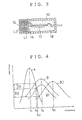
- FIG. 3 is a sectional view showing the structure of the proximity switch in which the coils L1 and L2 of the two tank circuits T1 and T2, respectively, are placed under a same thermal environment.
- the coils L1 and L2 of the tank circuits T1 and T2, respectively are placed in pot cores 14 and 15, respectively, each having an annular recess for receiving a coil winding therein, and the detection coil L2 is placed on the front end of the proximity switch.
- the two coils L1 and L2 are placed in tandem close to each other, the coil L1 is protected from external magnetic influences but the coil L2 is exposed to external magnetic influences and is therefore suitable for detecting an object.
- the case 16 accommodates therein a printed circuit board 17 carrying the oscillation circuit 13, the detector circuit 3, the comparison circuit 5 and so on.
- the clearance in the interior of the case 16 of this proximity switch is filled with filling material such as epoxy resin 18.
- the curves A and B denote the changes in the amplitude levels of the two tank circuits T1 and T2 with respect to frequency.
- the resonant frequency of the tank circuit T1 is set at a relatively low frequency f1 while the resonant frequency of the tank circuit T2 is set at a relatively high frequency f2.
- the oscillation circuit 13 oscillates at the frequency which maximizes the overall gain of the circuit, or, in other words, at which the amplitude levels of the two tank circuit cross each other.
- the loss of the detection coil L2 of the second tank circuit T2 increases as an iron object comes close to the detection coil L2, and its amplitude level changes as indicated by the curve B1. Therefore, since the oscillation frequency fo slightly rises to f01 and the amount of positive feedback accordingly diminishes, the amplitude of the oscillation circuit 13 also diminishes. This reduction in the amplitude is indicated by the difference D1 between the crossing points between the curves A and B and the curves A and B1 as shown in Figure 4.
- the amplitude property changes in such a manner that the oscillation frequency f2 rises to f21 as indicated by the shift from the curve B to the curve B2.
- the difference D2 is set to be substantially larger than the difference D1, it is possible to detect nonmagnetic metallic objects alone without being affected by magnetic objects by appropriately setting the threshold level of the comparator circuit 5.
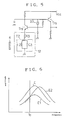
- the second tank coil circuit T2 was connected to the positive feedback loop of the oscillation circuit using an LC resonant circuit and its coil was used as the detection coil, but it is also possible to provide the second tank circuit T2 in the positive feedback loop of a crystal oscillation circuit, and to use its coil as a detection coil.
- a crystal oscillator 20 is connected between the base and collector of a transistor Tr2, and the output from its collector is supplied to an external circuit via an emitter follower transistor Tr3.
- a positive feedback circuit 12 having a second tank circuit T2 is connected between the emitter of the transistor Tr2 and ground.
- the impedance of the tank circuit T2 as seen from the base of the transistor Tr2 changes according to the approach of an object.
- the oscillation frequency is substantially fixed owing to the use of the crystal oscillator, and the amplitude of the oscillation circuit changes according to the changes in the resonant frequency of the positive feedback tank circuit and its property in regard to the object.
- the amplitude property of the tank circuit T2 when there is no object in proximity is represented by the curve E
- the amplitude property when there are an iron object and an aluminum object have come to a certain distance are expressed by the curves E1 and E2, respectively. It is possible to achieve a uniform sensitivity by arranging the tank circuit in such a manner that the amounts of reduction in the amplitude may become identical when either an iron object or an aluminum object is brought to a certain proximity.
- the circuit structure is identical to that of the first embodiment illustrated in the block diagram shown in Figure 1 and the circuit diagram shown in Figure 2.
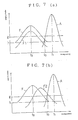
- the resonant frequency f3 of the second tank circuit T2 is set so as to be lower than the resonant frequency f1 of the first tank circuit T1 so that no oscillation takes place under normal condition and only aluminum objects may be detected.
- Figures 7(a) and 7(b) show the amplitude curves F1 and F2 representing the approach of an iron object and an aluminum object, respectively, as well as the amplitude curve F representing the state in which no object is in proximity.
- the circuit structure is identical to that of the first embodiment illustrated in the block diagram shown in Figure 1 and the circuit diagram shown in Figure 2, and the resonant frequency of the second tank circuit T2 is selected to be lower than the resonant frequency f3 of the first tank circuit T1 in the same way as in the previous embodiment.
- the threshold level of the comparator circuit is set at the level h in the graphs of Figures 7(a) and 7(b).
Landscapes
- Physics & Mathematics (AREA)
- Engineering & Computer Science (AREA)
- Remote Sensing (AREA)
- Life Sciences & Earth Sciences (AREA)
- Electromagnetism (AREA)
- Environmental & Geological Engineering (AREA)
- Geology (AREA)
- General Life Sciences & Earth Sciences (AREA)
- General Physics & Mathematics (AREA)
- Geophysics (AREA)
- Electronic Switches (AREA)
- Switches That Are Operated By Magnetic Or Electric Fields (AREA)
Applications Claiming Priority (2)
| Application Number | Priority Date | Filing Date | Title |
|---|---|---|---|
| JP1134234A JPH02312316A (ja) | 1989-05-26 | 1989-05-26 | 高周波発振型近接スイッチ |
| JP134234/89 | 1989-05-26 |
Publications (2)
| Publication Number | Publication Date |
|---|---|
| EP0399563A2 true EP0399563A2 (de) | 1990-11-28 |
| EP0399563A3 EP0399563A3 (de) | 1991-07-17 |
Family
ID=15123563
Family Applications (1)
| Application Number | Title | Priority Date | Filing Date |
|---|---|---|---|
| EP19900110062 Withdrawn EP0399563A3 (de) | 1989-05-26 | 1990-05-28 | Näherungsschalter des Hochfrequenzschwingungstyps |
Country Status (3)
| Country | Link |
|---|---|
| US (1) | US5034704A (de) |
| EP (1) | EP0399563A3 (de) |
| JP (1) | JPH02312316A (de) |
Cited By (9)
| Publication number | Priority date | Publication date | Assignee | Title |
|---|---|---|---|---|
| EP0670505A1 (de) * | 1994-03-04 | 1995-09-06 | Schneider Electric Sa | Induktive Näherungssensor |
| WO1996005522A3 (en) * | 1994-08-09 | 1996-05-23 | Micro Tag Temed Ltd | Method for labeling, verification and/or identifying and device for implementing said method |
| FR2735224A1 (fr) * | 1995-06-08 | 1996-12-13 | Silec Liaisons Elec | Capteur electromagnetique et procede de determination simultanee de differents parametres d'une cible associee |
| DE102009044820A1 (de) | 2009-12-08 | 2011-06-09 | Turck Holding Gmbh | Selbstkalibrierender Näherungsschalter |
| DE102011016504A1 (de) * | 2011-04-08 | 2012-10-11 | Behr-Hella Thermocontrol Gmbh | Anzeigevorrichtung für eine Fahrzeugkomponente |
| GB2495104A (en) * | 2011-09-28 | 2013-04-03 | Oxford Rf Sensors Ltd | Rotor blade sensor |
| GB2506424A (en) * | 2012-09-28 | 2014-04-02 | Salunda Ltd | Target clearance measurement device |
| US9859051B2 (en) | 2012-06-11 | 2018-01-02 | Powerbyproxi Limited | Magnetically permeable core for use in wireless power transfer systems |
| US11043841B2 (en) | 2016-05-25 | 2021-06-22 | Apple Inc. | Coil arrangement |
Families Citing this family (14)
| Publication number | Priority date | Publication date | Assignee | Title |
|---|---|---|---|---|
| EP0523563A1 (de) * | 1991-07-15 | 1993-01-20 | Omron Corporation | Annäherungsschalter |
| JPH05110412A (ja) * | 1991-10-15 | 1993-04-30 | Omron Corp | 発振回路及び高周波発振型近接スイツチ |
| DE4330140C2 (de) * | 1993-09-07 | 1997-07-17 | Ifm Electronic Gmbh | Induktiver Näherungsschalter |
| US5582184A (en) * | 1993-10-13 | 1996-12-10 | Integ Incorporated | Interstitial fluid collection and constituent measurement |
| US5801530A (en) * | 1995-04-17 | 1998-09-01 | Namco Controls Corporation | Proximity sensor having a non-ferrous metal shield for enhanced sensing range |
| US6476604B1 (en) * | 1999-04-12 | 2002-11-05 | Chartered Semiconductor Manufacturing Ltd. | Method and apparatus for identifying high metal content on a semiconductor surface |
| US6446012B1 (en) * | 1999-06-23 | 2002-09-03 | Bfcs Technology, Inc. | Proximity detector for hard-to-detect materials |
| ITMO20030300A1 (it) * | 2003-11-07 | 2005-05-08 | M D Micro Detectors Spa | Sensore di prossimita' induttivo, in particolare per rilevare la presenza di materiali ferrosi e non ferrosi |
| JP4385825B2 (ja) * | 2004-03-31 | 2009-12-16 | オムロン株式会社 | 近接センサ |
| US7511482B2 (en) * | 2005-08-31 | 2009-03-31 | I F M Electronic Gmbh | Inductive proximity switch |
| US8432169B2 (en) * | 2007-09-20 | 2013-04-30 | Panasonic Corporation | Proximity sensor |
| US8258777B2 (en) * | 2009-09-04 | 2012-09-04 | Weihua Chen | Inductive proximity sensor |
| US9753068B2 (en) * | 2015-01-14 | 2017-09-05 | Insitu Inc. | Systems and methods for signal quantization |
| CN110109183B (zh) * | 2019-04-29 | 2024-04-19 | 于凯鸿 | 一种检测物体接近的传感装置 |
Family Cites Families (11)
| Publication number | Priority date | Publication date | Assignee | Title |
|---|---|---|---|---|
| DE1302191B (de) * | 1960-11-24 | 1971-01-14 | ||
| FR1344681A (fr) * | 1963-01-14 | 1963-11-29 | Tateisi Denki Kabushikikaisha | Appareil détecteur électrique |
| CH421237A (de) * | 1964-02-05 | 1966-09-30 | Ebauches Sa | Näherungsdetektor |
| DE1915044A1 (de) * | 1969-03-25 | 1970-10-15 | Schaller Dipl Ing Werner | Induktiver Naeherungsschalter |
| US3896371A (en) * | 1973-12-17 | 1975-07-22 | Allen W Hametta | Metal detector with a resonating circuit being driven by a frequency higher than its natural resonance frequency |
| US3961238A (en) * | 1975-01-22 | 1976-06-01 | Robert F. Gardiner | Selective metal detector circuit having dual tuned resonant circuits |
| FR2320663A1 (fr) * | 1975-08-06 | 1977-03-04 | Itt Produits Ind | Detecteur de proximite d'objets de toute nature |
| US4263553A (en) * | 1978-05-30 | 1981-04-21 | Cook Kenneth M | Discriminating metal detector with compensation for ground minerals |
| DE3228524C2 (de) * | 1982-07-30 | 1985-05-02 | Siemens AG, 1000 Berlin und 8000 München | Induktiver Annäherungsschalter |
| JPH069336B2 (ja) * | 1987-04-03 | 1994-02-02 | 本田技研工業株式会社 | 高周波発振型近接スイツチ |
| DE3714433C2 (de) * | 1987-04-30 | 1994-04-28 | Turck Werner Kg | Induktiver Näherungsschalter |
-
1989
- 1989-05-26 JP JP1134234A patent/JPH02312316A/ja active Pending
-
1990
- 1990-05-28 EP EP19900110062 patent/EP0399563A3/de not_active Withdrawn
- 1990-05-29 US US07/529,357 patent/US5034704A/en not_active Expired - Lifetime
Cited By (17)
| Publication number | Priority date | Publication date | Assignee | Title |
|---|---|---|---|---|
| EP0670505A1 (de) * | 1994-03-04 | 1995-09-06 | Schneider Electric Sa | Induktive Näherungssensor |
| FR2716979A1 (fr) * | 1994-03-04 | 1995-09-08 | Telemecanique | Détecteur de proximité inductif. |
| US5519317A (en) * | 1994-03-04 | 1996-05-21 | Schneider Electric Sa | Inductive proximity sensor for detecting ferrous and non-ferrous objects |
| WO1996005522A3 (en) * | 1994-08-09 | 1996-05-23 | Micro Tag Temed Ltd | Method for labeling, verification and/or identifying and device for implementing said method |
| US5986550A (en) * | 1994-08-09 | 1999-11-16 | Micro Tag Temed Ltd. | Method for labeling, verification and/or identifying and device for implementing the method |
| FR2735224A1 (fr) * | 1995-06-08 | 1996-12-13 | Silec Liaisons Elec | Capteur electromagnetique et procede de determination simultanee de differents parametres d'une cible associee |
| WO1996042138A1 (fr) * | 1995-06-08 | 1996-12-27 | Sagem Sa | Capteur electromagnetique et procede de determination simultanee de differents parametres d'une cible associee |
| DE102009044820B4 (de) * | 2009-12-08 | 2011-09-01 | Turck Holding Gmbh | Selbstkalibrierender Näherungsschalter |
| DE102009044820A1 (de) | 2009-12-08 | 2011-06-09 | Turck Holding Gmbh | Selbstkalibrierender Näherungsschalter |
| DE102011016504A1 (de) * | 2011-04-08 | 2012-10-11 | Behr-Hella Thermocontrol Gmbh | Anzeigevorrichtung für eine Fahrzeugkomponente |
| DE102011016504B4 (de) * | 2011-04-08 | 2013-07-18 | Behr-Hella Thermocontrol Gmbh | Anzeigevorrichtung für eine Fahrzeugkomponente |
| GB2495104A (en) * | 2011-09-28 | 2013-04-03 | Oxford Rf Sensors Ltd | Rotor blade sensor |
| US9030212B2 (en) | 2011-09-28 | 2015-05-12 | Salunda Limited | Target sensor |
| US9859051B2 (en) | 2012-06-11 | 2018-01-02 | Powerbyproxi Limited | Magnetically permeable core for use in wireless power transfer systems |
| GB2506424A (en) * | 2012-09-28 | 2014-04-02 | Salunda Ltd | Target clearance measurement device |
| GB2506424B (en) * | 2012-09-28 | 2017-06-07 | Salunda Ltd | Target clearance measurement device |
| US11043841B2 (en) | 2016-05-25 | 2021-06-22 | Apple Inc. | Coil arrangement |
Also Published As
| Publication number | Publication date |
|---|---|
| US5034704A (en) | 1991-07-23 |
| EP0399563A3 (de) | 1991-07-17 |
| JPH02312316A (ja) | 1990-12-27 |
Similar Documents
| Publication | Publication Date | Title |
|---|---|---|
| US5034704A (en) | High frequency oscillation type proximity switch | |
| US5012206A (en) | Inductive proximity switch | |
| US5767672A (en) | Inductive proximity sensor for detecting magnetic and non-magnetic metallic objects | |
| US4509023A (en) | Oscillator with a temperature compensated oscillating coil | |
| US4782308A (en) | Circuit arrangement of a reading device for electromagnetic identification cards | |
| CA1155174A (en) | Voltage regulator using saturable transformer | |
| US6335619B1 (en) | Inductive proximity sensor comprising a resonant oscillatory circuit responding to changes in inductive reaction | |
| CA2284600A1 (en) | Apparatus for magnetically decoupling an rfid tag | |
| US5010313A (en) | Chip coil | |
| US10608587B2 (en) | Crystal oscillator circuit | |
| EP0601515B1 (de) | Oszillatorschaltung | |
| US5065138A (en) | Magnetically-coupled two-resonant-circuit, frequency divider for presence-detection-system tag | |
| US3503007A (en) | Controllable oscillator | |
| US5264809A (en) | Oscillator circuit and proximity switch using | |
| CN109120231A (zh) | 快速起振的单接点石英振荡装置及操作方法 | |
| US3707686A (en) | Non-contact switching device including oscillator controlled by movable magnets | |
| US20030071708A1 (en) | Inductive proximity switch | |
| JP2000131120A (ja) | 磁性体のレベル検知装置 | |
| US4868499A (en) | Object detector with feedback which holds constant the product of the transmitter coil current and frequency to maintain constant sensor voltage output | |
| JPS5896424A (ja) | 近接スイツチ | |
| US20070096911A1 (en) | High temperature product identification system and method | |
| SU1274145A1 (ru) | Бесконтактный выключатель | |
| JPS60235524A (ja) | 近接スイツチ | |
| JPS5673906A (en) | Microwave oscillator | |
| SU1166194A1 (ru) | Бесконтактный путевой переключатель |
Legal Events
| Date | Code | Title | Description |
|---|---|---|---|
| PUAI | Public reference made under article 153(3) epc to a published international application that has entered the european phase |
Free format text: ORIGINAL CODE: 0009012 |
|
| 17P | Request for examination filed |
Effective date: 19900625 |
|
| AK | Designated contracting states |
Kind code of ref document: A2 Designated state(s): AT BE CH DE DK ES FR GB GR IT LI NL SE |
|
| PUAL | Search report despatched |
Free format text: ORIGINAL CODE: 0009013 |
|
| AK | Designated contracting states |
Kind code of ref document: A3 Designated state(s): AT BE CH DE DK ES FR GB GR IT LI NL SE |
|
| 17Q | First examination report despatched |
Effective date: 19940317 |
|
| STAA | Information on the status of an ep patent application or granted ep patent |
Free format text: STATUS: THE APPLICATION IS DEEMED TO BE WITHDRAWN |
|
| 18D | Application deemed to be withdrawn |
Effective date: 19960109 |