EP0399576A1 - Apparatus for regulating the inflow of fuel into the intake duct of an internal combustion engine - Google Patents
Apparatus for regulating the inflow of fuel into the intake duct of an internal combustion engine Download PDFInfo
- Publication number
- EP0399576A1 EP0399576A1 EP90200628A EP90200628A EP0399576A1 EP 0399576 A1 EP0399576 A1 EP 0399576A1 EP 90200628 A EP90200628 A EP 90200628A EP 90200628 A EP90200628 A EP 90200628A EP 0399576 A1 EP0399576 A1 EP 0399576A1
- Authority
- EP
- European Patent Office
- Prior art keywords
- fuel
- inflow
- regulating
- intake duct
- electrovalve
- Prior art date
- Legal status (The legal status is an assumption and is not a legal conclusion. Google has not performed a legal analysis and makes no representation as to the accuracy of the status listed.)
- Withdrawn
Links
- 239000000446 fuel Substances 0.000 title claims abstract description 53
- 230000001105 regulatory effect Effects 0.000 title claims abstract description 14
- 238000002485 combustion reaction Methods 0.000 title claims abstract description 12
- 210000000056 organ Anatomy 0.000 claims abstract description 10
- 230000005284 excitation Effects 0.000 claims abstract description 7
- 238000011144 upstream manufacturing Methods 0.000 claims description 2
- 230000001276 controlling effect Effects 0.000 claims 1
- 239000000203 mixture Substances 0.000 abstract description 4
- 238000002347 injection Methods 0.000 description 13
- 239000007924 injection Substances 0.000 description 13
- 230000006870 function Effects 0.000 description 4
- 230000032683 aging Effects 0.000 description 1
- 238000004891 communication Methods 0.000 description 1
- 238000013016 damping Methods 0.000 description 1
- 238000010586 diagram Methods 0.000 description 1
- 238000009792 diffusion process Methods 0.000 description 1
- 238000009434 installation Methods 0.000 description 1
- 238000004519 manufacturing process Methods 0.000 description 1
- 238000012986 modification Methods 0.000 description 1
- 230000004048 modification Effects 0.000 description 1
- 230000010355 oscillation Effects 0.000 description 1
- 230000002085 persistent effect Effects 0.000 description 1
- 230000010349 pulsation Effects 0.000 description 1
- 239000000243 solution Substances 0.000 description 1
Images
Classifications
-
- F—MECHANICAL ENGINEERING; LIGHTING; HEATING; WEAPONS; BLASTING
- F02—COMBUSTION ENGINES; HOT-GAS OR COMBUSTION-PRODUCT ENGINE PLANTS
- F02M—SUPPLYING COMBUSTION ENGINES IN GENERAL WITH COMBUSTIBLE MIXTURES OR CONSTITUENTS THEREOF
- F02M7/00—Carburettors with means for influencing, e.g. enriching or keeping constant, fuel/air ratio of charge under varying conditions
- F02M7/12—Other installations, with moving parts, for influencing fuel/air ratio, e.g. having valves
- F02M7/18—Other installations, with moving parts, for influencing fuel/air ratio, e.g. having valves with means for controlling cross-sectional area of fuel-metering orifice
- F02M7/20—Other installations, with moving parts, for influencing fuel/air ratio, e.g. having valves with means for controlling cross-sectional area of fuel-metering orifice operated automatically, e.g. dependent on altitude
-
- F—MECHANICAL ENGINEERING; LIGHTING; HEATING; WEAPONS; BLASTING
- F02—COMBUSTION ENGINES; HOT-GAS OR COMBUSTION-PRODUCT ENGINE PLANTS
- F02D—CONTROLLING COMBUSTION ENGINES
- F02D35/00—Controlling engines, dependent on conditions exterior or interior to engines, not otherwise provided for
- F02D35/0015—Controlling engines, dependent on conditions exterior or interior to engines, not otherwise provided for using exhaust gas sensors
- F02D35/0046—Controlling fuel supply
- F02D35/0053—Controlling fuel supply by means of a carburettor
- F02D35/0069—Controlling the fuel flow only
Definitions
- the present invention relates to an apparatus for regulating the inflow of fuel into the intake duct of an internal combustion engine.
- the purpose of the present invention is of proposing an apparatus for regulating the inflow of fuel for internal combustion engines, which automatically considers said changes, and therefore corrects the amount of fuel mixed with air, independently on the algorism of control of the times of actuation of fuel feed electrovalve.
- an apparatus for the regulation of the inflow of fuel into the intake duct of a controlled-ignition internal combustion engine comprising at least one electrovalve installed in a fuel feed duct leading to the intake duct downstream the speed governor organ and connected with a control unit suitable for regulating the times of excitation of the coil of said electrovalve as a function of the current values of operating parameters of the engine, characterized in that said fuel inflow duct is connected with at least one fuel container cup equipped with a device for regulating the fuel level inside said cup, and that said electrovalve is substantially positioned at the same level as of said fuel container cup.
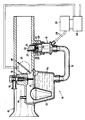
- a regulation apparatus which comprises at least one electrovalve, in particular an electroinjector 11, connected, through a pipe 12, with at least one cup 13 destined to contain fuel 14, which fuel inflows into said cup from an external duct 15 through an usual valve 16 controlled by an automatic filling apparatus 17, for example of the floating-body type, which ensures a constant level of fuel inside said cup 13.
- the interior of the cup 13 is in communication, through a duct 18, with the external environment, and precisely with the portion of the intake duct 19 which is positioned upstream the speed governor organ 30, which in this case is represented as a traditional throttle valve.
- the pipe 12 in which the electroinjector 11 is installed leads to the intake duct 19 downstream said speed governor organ.
- the electroinjector 11 is composed by a body 20, provided with a bore 21 positioned at the centre of its circular end surface 22; through said bore 21 the fuel, contained inside an inner cylindrical chamber 23, flows, with said bore 21 being normally shut bu a mobile core 24, which is maintained in its position shown in the figure by the thrust applied to it by a spring 25.
- the body 20 of the electroinjector is positioned laterally to the body of the intake duct 19 by means of a centering sleeve 26 with which a diffuser 27 is connected as well.
- said diffuser 27 is provided with an outlet surface so inclined as to favour the outflowing of fuel into the intake duct, and the consequent mixing thereof with the air stream flowing along the same intake duct.
- the electrovalve is substantially positioned at the same level as of the cup 13.
- the bore 21 controlled by the electrovalve is positioned at a level substantially corresponding to the level of fuel inside the cup 13.
- the coil of the injector 11 is connected, through two leads 28, with a pilot circuit 29 which controls the time of excitation, and the duration of excitation of said coil, as a function of a control algorism implemented in the electronic control unit 40; said control algorism takes into account, in the present exemplifying form of practical embodiment, the signals coming from a transducer of position 31 of the speed governor organ 30, and from a transducer of revolution speed of the internal combustion engine, which latter transducer is not shown in figure, in that it is per se known.
- the above disclosed apparatus operates as follows.
- the amount of fuel which should be fed at each revolution of the engine into the intake duct 19 is preliminarily determined by means of purposely designed engine operating tests and is then stored, as a map of values of electroinjector excitation times in the electronic memory of the control unit 40; all the above, under perfect analogy with what occurs in the various systems of control of the injection in internal combustion engines, which are based on electronic control units according to the prior art.
- the pressure due to the difference between the level of fuel inside the cup 13 and the position of the outlet bore 21 of the electroinjector 11 is in fact negligible, or anyway equivalent to that which one has in carburettor feed systems; therefore, the amount of fuel inflowing into the intake duct 19 depends, besides the times of opening of the bore 21, also on the depressure which is generated inside the same duct, analogously to what happens, as regards this second aspect, in the so-said aspirated engines.
- the self-correction compensates for the changes in the amount of intaken air, due to the unforeseeable and non-determinable operating parameters, i.e., due to those operating parameters which cannot be taken into consideration in order to generate and store the map of values which constitutes the basis of the control algorism; parameters, which constitute reasons of criticality of the correct operation over time of the injection control systems according to the prior art.
Landscapes
- Engineering & Computer Science (AREA)
- Chemical & Material Sciences (AREA)
- Combustion & Propulsion (AREA)
- Mechanical Engineering (AREA)
- General Engineering & Computer Science (AREA)
- Electrical Control Of Air Or Fuel Supplied To Internal-Combustion Engine (AREA)
- Control Of The Air-Fuel Ratio Of Carburetors (AREA)
Applications Claiming Priority (2)
| Application Number | Priority Date | Filing Date | Title |
|---|---|---|---|
| IT8920266A IT1229666B (it) | 1989-04-24 | 1989-04-24 | Apparato per la regolazione dell'afflusso di carburante nel condotto di aspirazione di un motore a c.i.. |
| IT2026689 | 1989-04-24 |
Publications (1)
| Publication Number | Publication Date |
|---|---|
| EP0399576A1 true EP0399576A1 (en) | 1990-11-28 |
Family
ID=11165272
Family Applications (1)
| Application Number | Title | Priority Date | Filing Date |
|---|---|---|---|
| EP90200628A Withdrawn EP0399576A1 (en) | 1989-04-24 | 1990-03-19 | Apparatus for regulating the inflow of fuel into the intake duct of an internal combustion engine |
Country Status (4)
| Country | Link |
|---|---|
| US (1) | US5036818A (it) |
| EP (1) | EP0399576A1 (it) |
| JP (1) | JPH02301654A (it) |
| IT (1) | IT1229666B (it) |
Families Citing this family (1)
| Publication number | Priority date | Publication date | Assignee | Title |
|---|---|---|---|---|
| US7761222B1 (en) * | 2008-12-29 | 2010-07-20 | Caterpillar Inc | Fuel injector flow shift compensation in internal combustion engine |
Citations (5)
| Publication number | Priority date | Publication date | Assignee | Title |
|---|---|---|---|---|
| US2768819A (en) * | 1951-02-19 | 1956-10-30 | Jr Albert G Bodine | Engine fuel system |
| DE2529663A1 (de) * | 1972-04-22 | 1977-01-27 | Bosch Gmbh Robert | Einrichtung zur regelung des massenverhaeltnisses des einer brennkraftmaschine zugefuehrten kraftstoff-luft-gemisches |
| US4088100A (en) * | 1974-12-02 | 1978-05-09 | Nissan Motor Company, Limited | Air/fuel ratio control system in internal combustion engine |
| GB2041088A (en) * | 1979-02-09 | 1980-09-03 | Sibe | Improvements in carburettors for internal combustion engines |
| US4766867A (en) * | 1987-08-03 | 1988-08-30 | Gantenbine Harvey A | Fuel supply system for internal combustion engine |
Family Cites Families (12)
| Publication number | Priority date | Publication date | Assignee | Title |
|---|---|---|---|---|
| DE2639920A1 (de) * | 1976-09-04 | 1978-03-09 | Volkswagenwerk Ag | Kraftstoff-einspritzeinrichtung |
| JPS5820948A (ja) * | 1981-07-29 | 1983-02-07 | Mikuni Kogyo Co Ltd | 内燃機関の燃料供給装置 |
| US4409944A (en) * | 1981-08-05 | 1983-10-18 | Pierburg Gmbh & Co. Kg | Fuel supply system |
| JPS58160520A (ja) * | 1981-12-31 | 1983-09-24 | オ−ビタル・エンジン・カンパニイ・プロプライエタリ・リミテツド | 内燃機関用燃料噴射装置 |
| JPS61171871A (ja) * | 1985-01-25 | 1986-08-02 | Hitachi Ltd | 燃料霧化装置付燃料供給装置 |
| JP2507315B2 (ja) * | 1986-03-26 | 1996-06-12 | 株式会社日立製作所 | 内燃機関制御装置 |
| US4799467A (en) * | 1986-07-16 | 1989-01-24 | Honda Giken Kogyo Kabushiki Kaisha | Throttle valve control system for an internal combustion engine |
| KR950009044B1 (ko) * | 1987-06-17 | 1995-08-14 | 가부시키가이샤 히타치세이사쿠쇼 | 발열저항식 공기유량측정장치 |
| JPH0799110B2 (ja) * | 1987-08-17 | 1995-10-25 | 本田技研工業株式会社 | 内燃エンジンの空燃比フィ−ドバック制御方法 |
| JPH01113540A (ja) * | 1987-10-26 | 1989-05-02 | Mazda Motor Corp | エンジンの制御装置 |
| US4796579A (en) * | 1988-03-02 | 1989-01-10 | Ford Motor Company | Automotive type throttle body |
| JP2759957B2 (ja) * | 1988-03-09 | 1998-05-28 | 株式会社日立製作所 | エンジン制御方法 |
-
1989
- 1989-04-24 IT IT8920266A patent/IT1229666B/it active
-
1990
- 1990-03-15 US US07/493,645 patent/US5036818A/en not_active Expired - Fee Related
- 1990-03-19 EP EP90200628A patent/EP0399576A1/en not_active Withdrawn
- 1990-04-17 JP JP2100177A patent/JPH02301654A/ja active Pending
Patent Citations (5)
| Publication number | Priority date | Publication date | Assignee | Title |
|---|---|---|---|---|
| US2768819A (en) * | 1951-02-19 | 1956-10-30 | Jr Albert G Bodine | Engine fuel system |
| DE2529663A1 (de) * | 1972-04-22 | 1977-01-27 | Bosch Gmbh Robert | Einrichtung zur regelung des massenverhaeltnisses des einer brennkraftmaschine zugefuehrten kraftstoff-luft-gemisches |
| US4088100A (en) * | 1974-12-02 | 1978-05-09 | Nissan Motor Company, Limited | Air/fuel ratio control system in internal combustion engine |
| GB2041088A (en) * | 1979-02-09 | 1980-09-03 | Sibe | Improvements in carburettors for internal combustion engines |
| US4766867A (en) * | 1987-08-03 | 1988-08-30 | Gantenbine Harvey A | Fuel supply system for internal combustion engine |
Non-Patent Citations (3)
| Title |
|---|
| PATENT ABSTRACTS OF JAPAN vol. 8, no. 186 (M-320) 25 August 1984, & JP-A-59 077064 (MIKUNI KOGYO KK.) 02 May 1984, * |
| PATENT ABSTRACTS OF JAPAN vol. 8, no. 5 (M-267) 11 January 1984, & JP-A-58 167867 (HITACHI SEISAKUSHO KK.) 04 October 1983, * |
| PATENT ABSTRACTS OF JAPAN vol. 9, no. 63 (M-365) 20 March 1985, & JP-A-59 196949 (MITSUBISHI JIDOSHA KOGYO K.K.) 8 November 1983, * |
Also Published As
| Publication number | Publication date |
|---|---|
| IT1229666B (it) | 1991-09-06 |
| IT8920266A0 (it) | 1989-04-24 |
| US5036818A (en) | 1991-08-06 |
| JPH02301654A (ja) | 1990-12-13 |
Similar Documents
| Publication | Publication Date | Title |
|---|---|---|
| US5284120A (en) | Fuel consumption measuring device | |
| US3963009A (en) | Carburation devices for internal combustion engines | |
| US3855974A (en) | Apparatus to control the air-fuel mixture supplied to internal combustion engines | |
| US4453523A (en) | Pressure balanced flow regulator for gaseous fuel engine | |
| US6698727B1 (en) | Electronic control diaphragm carburetor | |
| GB2070287A (en) | Pressure regulating device | |
| GB2059503A (en) | Fuel Supply Devices for Multi- cylinder Internal Combustion Engines | |
| US4442818A (en) | Fuel injection apparatus for internal combustion engines | |
| US3857908A (en) | Apparatus for controlling and modulating engine functions | |
| US4411233A (en) | Carburation devices for internal combustion engines | |
| US3951121A (en) | Fuel injection system | |
| US3794302A (en) | Floatless carburetor for internal combustion engines | |
| US4381751A (en) | Fuel injection system | |
| US4383513A (en) | Fuel injection system | |
| US4387063A (en) | Carburettors comprising a main fuel circuit and an auxiliary circuit | |
| US4071585A (en) | Variable venturi type carburetor | |
| US4214565A (en) | Fuel injection apparatus | |
| US6702261B1 (en) | Electronic control diaphragm carburetor | |
| US2879046A (en) | Fuel distributing valve for fuel injection system | |
| US5207205A (en) | Fuel injection device with air-assisted fuel diffusion | |
| US3967607A (en) | Fuel injection system | |
| US4172436A (en) | Carburation devices for internal combustion engines | |
| US5036818A (en) | Apparatus for regulating the inflow of fuel into the intake duct of an internal combustion engine | |
| US4263235A (en) | Mixture preparation apparatus | |
| GB2132700A (en) | Fuel injection system |
Legal Events
| Date | Code | Title | Description |
|---|---|---|---|
| PUAI | Public reference made under article 153(3) epc to a published international application that has entered the european phase |
Free format text: ORIGINAL CODE: 0009012 |
|
| AK | Designated contracting states |
Kind code of ref document: A1 Designated state(s): AT BE CH DE ES FR GB LI NL |
|
| RAP1 | Party data changed (applicant data changed or rights of an application transferred) |
Owner name: PIAGGIO VEICOLI EUROPEI S.R.L. |
|
| 17P | Request for examination filed |
Effective date: 19901224 |
|
| 17Q | First examination report despatched |
Effective date: 19910612 |
|
| STAA | Information on the status of an ep patent application or granted ep patent |
Free format text: STATUS: THE APPLICATION IS DEEMED TO BE WITHDRAWN |
|
| 18D | Application deemed to be withdrawn |
Effective date: 19911224 |